Table of Contents
Advertisement
Quick Links
F
M
IELD
AG
Standard Model
For use in non-hazardous locations
HL Model
For use in hazardous locations:
• Class I, Division 2, Groups A-D, T5
• Class I, Zone 2 IIC T5
WARNING!
!
Incorrect installation or removal of
meters can result in serious injury or
death. Read the instructions in this guide
on the proper procedures carefully.
•
Any person installing, inspecting, or
maintaining a McCrometer flowmeter
should have a working understanding of
piping configurations and systems under
pressure.
•
Before adjusting or removing any meter,
be certain the system has depressurized
completely.
•
Be careful when lifting meters. Meters can
cause serious injury if lifted incorrectly or
dropped.
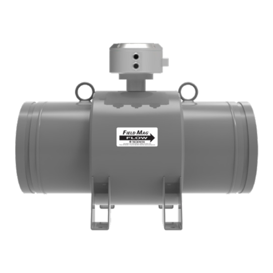
®
Electromagnetic Flow Meter
Field Mag 3000
Quick Start Installation Guide
About This Quick Start Guide
This Quick Start Guide is a supplement to the
Installation, Operation and Maintenance manual
supplied with this meter. It is intended to be a quick
reference for the basic installation and reading of the
Field Mag.
It is designed to provide installation instructions
when the location of the sensor installation has been
predetermined.
Refer to the meter manual (30126-45 Field Mag 3000
IOM manual) for information on these topis:
•
Preparation and planning for installation
•
Site location
•
Software configuration
•
Detailed information on external connections,
external power, outputs
About This Quick Start Guide. . . . . . . . . . . . . . . . .1
1.
Check Shipping Crate Contents . . . . . . . . . . .2
2.
Check Serial Numbers . . . . . . . . . . . . . . . . .2
3.
Pipe Run Requirements . . . . . . . . . . . . . . . .2
4.
Sensor Position and Location . . . . . . . . . . . .2
5.
Flow Meter Installation . . . . . . . . . . . . . . . .3
6.
Example Remote Mount Configuration . . . . . .3
7.
Conduit . . . . . . . . . . . . . . . . . . . . . . . . . .4
8.
Wiring Diagrams. . . . . . . . . . . . . . . . . . . . .5
9.
Grounding . . . . . . . . . . . . . . . . . . . . . . . .6
10.
Activating The Display . . . . . . . . . . . . . . . . .7
11.
Converter Boot. . . . . . . . . . . . . . . . . . . . . .7
12.
Converter Configuration . . . . . . . . . . . . . . .8
13.
Error Messages for Troubleshooting . . . . . . . .8
Page 1
30126-62 Rev. 1.0 | 02JAN2024
Advertisement
Table of Contents

Related Manuals for McCrometer Field Mag 3000


Summary of Contents for McCrometer Field Mag 3000
- Page 1 Field Mag. It is designed to provide installation instructions when the location of the sensor installation has been predetermined. Refer to the meter manual (30126-45 Field Mag 3000 IOM manual) for information on these topis: Standard Model • Preparation and planning for installation For use in non-hazardous locations •...
- Page 2 When uncrating the Field Mag, any damage due to Pipe Run Requirements rough or improper handling should be reported to the transportation firm and McCrometer. If for The meter needs to be located a minimum any reason it is determined that the unit or parts...
- Page 3 IELD ® Horizontal installation factory.) Clamps should be In horizontal pipe runs, the meter should be bolted on tight, installed so that the junction box is vertical torquing insuring the electrodes are positioned to prevent not required. Refer coating by sediments or loss of electrode contact to section 9 for a due to air bubbles.
- Page 4 IELD ® Installing Cables through Cable Glands and Conduit All electrical cables enter the converter through compression fittings or optional customer- supplied conduit located on the side or bottom of the converter. Ensure that all compression glands are properly tightened and all unused fittings are plugged so the case remains sealed.
- Page 5 IELD ® Wiring Diagrams TERMINAL BLOCK ASSIGNMENTS Terminal Port Wire Color Green/Yellow Yellow Coils Harness Yellow Green / Yellow Terminal Port Wire Color Green/Yellow Pink Electrodes Black Blue Harness Blue Black Green / Yellow Pink Terminal Port Wire Color Pink Pulse Output Pink Brown...
- Page 6 See below for grounding examples, including the preferred method of grounding. When installing into a PVC or plastic pipe system, grounding rings for flanged meters are recommended for all sizes. For best performance, McCrometer provides grounding rings for all sizes. Speci cation Sheet...
- Page 7 IELD ® Activating The Display 12345 The display is activated when the lid is Default opened. The display will remain active for Rate display Rate unit 30 seconds. setting 123456789 GAL The various parts of the interface screen Total unit Total x1000 is shown below.
- Page 8 Copyright © 2023 McCrometer, Inc. All printed material should not be changed or altered without permission of McCrometer. Any published pricing, technical data, and instructions are subject to change without notice. Contact your McCrometer representative for current pricing, technical data, and instructions.
Need help?
Do you have a question about the Field Mag 3000 and is the answer not in the manual?
Questions and answers