Advertisement
Quick Links
FlowConnect
™
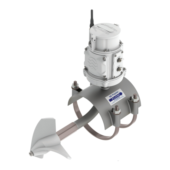
Retrofit Instruction: From remote mount Mc Propeller FlowCom unit to
This describes the procedure for retrofitting a Mc Propeller flow meter by replacing a FlowCom unit with a
FlowConnect unit at an existing remote mount location.
REPLACE THIS
Retrofit Instruction: From remote mount Mc Propeller FlowCom unit to FlowConnect unit
1 - Retrofit Procedure
STEP 1: Inventory the parts
STEP 2: Shut off or disconnect the power
STEP 3: Run replacement power and sensor
cables
STEP 4: Remove the strain relief and disconnect
the wires
STEP 5: Replace the submergible remote mount
kit at the meter head
STEP 6: Remove the FlowCom unit
STEP 7: Attach the FlowConnect unit at the
remote mount location
STEP 8: Attach the antenna
STEP 9: Connect the batteries and attach the
battery cover
STEP 10: Attach the tamper evident seals
FlowConnect FC500 Retrofit Instructions
FlowConnect unit
OVERVIEW OF THE PROCEDURE
2 - Installing Sensors and Solar Panel
3 - Connecting Inputs and Outputs
4 - Setting the New FlowCom Register
Page 1
WITH THIS
1: Recommended standards
2: Installing a solar panel
3: Installing a rain gauge
4: Installing a pressure sensor
1: Power connector
2: Inputs connector
3: Outputs connector
STEP 1: Enter PROGRAMMING MODE
STEP 2: Cycle through the first menu level
STEP 3: Cycle through the second menu level
STEP 4: Set the total
STEP 5: Exit and save settings
30122-37 Rev. 1.1 | 06APR2022
Advertisement

Related Manuals for McCrometer FlowConnect FC500


Summary of Contents for McCrometer FlowConnect FC500
- Page 1 FlowConnect FlowConnect FC500 Retrofit Instructions ™ Retrofit Instruction: From remote mount Mc Propeller FlowCom unit to FlowConnect unit OVERVIEW OF THE PROCEDURE This describes the procedure for retrofitting a Mc Propeller flow meter by replacing a FlowCom unit with a FlowConnect unit at an existing remote mount location.
-
Page 2: Parts And Materials
FlowConnect FlowConnect FC500 Retrofit Instructions ™ PARTS AND MATERIALS Part Number Description Quantity Part Number Description Quantity 30122-20 IOM Manual TOB049 O-ring, wall mount bracket 1-2802 Wall mount bracket TOB008 WS Base Plate TOB050 #10-32 screw with O-ring TOB018 O-Ring for Base Plate... - Page 3 FlowConnect FlowConnect FC500 Retrofit Instructions ™ 1 - Retrofit Procedure STEP 1: Inventory the parts Meter serial number engraved Check the parts received against the parts list on the on enclosure lid previous page. b. Compare the serial numbers engraved on the lids to confirm they match.
- Page 4 FlowConnect FlowConnect FC500 Retrofit Instructions ™ IMPORTANT! Do not loosen the bolts on the saddle or meter plate! Do not remove the saddle or meter plate! This step can be performed entirely with the flow meter intact in the pipe.
- Page 5 FlowConnect FlowConnect FC500 Retrofit Instructions ™ STEP 6: Remove the FlowCom unit WARNING! Do not proceed with step 6 until you are certain the power has been shut off. Cut the power and sensor cables from the FlowCom unit base.
- Page 6 FlowConnect FlowConnect FC500 Retrofit Instructions ™ STEP 8: Attach the antenna The antenna MUST be attached before the batteries are inserted! Powering up the unit without the antenna may damage the modem! Attach the cellular antenna or antenna extension by screwing it to the antenna post.
- Page 7 FlowConnect FlowConnect FC500 Retrofit Instructions ™ STEP 10: Attach the tamper evident seals When the retrofit is completed, attach the two tamper evident seals located the base plate (Figure 8) and the battery cover (Figure 9). There are already two other seals on the FlowConnect unit.
- Page 8 Because each user’s requirements and conditions will vary, McCrometer does not require any particular way of mounting or securing the sensor pole. However, we do provide recommended standards for how your sensor mount should be installed.
-
Page 9: Tools And Materials
FlowConnect FlowConnect FC500 Retrofit Instructions ™ 2: Installing a solar panel 3: Installing a rain gauge TOOLS AND MATERIALS TOOLS AND MATERIALS Tools and Materials: Tools and Materials: Solar Panel kit (200.733.522 or 200.733.520) Rain Gauge kit, model RG1 7 mm socket driver... - Page 10 FlowConnect FlowConnect FC500 Retrofit Instructions ™ 4: Installing a pressure sensor TOOLS AND MATERIALS Note: Sensor parts are sold individually or as a bundle. If you want to install a pressure sensor that can transmit The parts listed below are for sensor and cable bundles.
- Page 11 FlowConnect FlowConnect FC500 Retrofit Instructions ™ 3 - Connecting Inputs and Outputs IMPORTANT! Before purchasing any sensors, be sure to confirm that they are compatible with the FlowConnect system. Figure 11 and Figure 12 below show possible methods of connecting inputs, outputs, and external power to the FlowConnect system.
- Page 12 FlowConnect FlowConnect FC500 Retrofit Instructions ™ 1: Power connector For models with rechargeable batteries, a solar panel can be connected through the Power connector at the top of the connector plate. 2: Inputs connector The FlowConnect unit supports up to two analog inputs through the Inputs connector. Inputs are most often sensors, such as a rain gauge or a pressure sensor.
- Page 13 FlowConnect FlowConnect FC500 Retrofit Instructions ™ 4 - Setting the New FlowCom Register Brief explanation of why this is necessary: After a FlowCom unit has been replaced with a new FlowConnect unit, users may want to set the register with the total gallons amount from the previous register.
- Page 14 FlowConnect FlowConnect FC500 Retrofit Instructions ™ There are three activation points located on the outside of the register that are used to access the configuration menu as shown in Figure 14: • The P on the far right side is used for Approx.
- Page 15 FlowConnect FlowConnect FC500 Retrofit Instructions ™ First Menu Level STEP 2: Cycle through the first menu level Display Menu Title Description The first level menu selection appear in the order Program Lock Out Loc-CodE Enter w/ preset code shown in the table at right.
- Page 16 FlowConnect FlowConnect FC500 Retrofit Instructions ™ Second Menu Level STEP 3: Cycle through the second menu level Display Menu Title Description The second level menu selection appear in the order Parent Meter Serial # Par-S Sets Meter Serial No. shown in the table at right.
- Page 17 Copyright © 2022 McCrometer, Inc. All printed material should not be changed or altered without permission of McCrometer. Any published pricing, technical data, and instructions are subject to change without notice. Contact your McCrometer representative for current pricing, technical data, and instructions.
Need help?
Do you have a question about the FlowConnect FC500 and is the answer not in the manual?
Questions and answers