urmet domus 1068 User Manual
Remote managed alarm control panels
Hide thumbs
Also See for 1068:
- Installation and programming manual (152 pages) ,
- Quick manual (40 pages) ,
- Installation and configuration manual (40 pages)
Table of Contents
Advertisement
Quick Links
DS1068-045
REMOTE MANAGED ALARM CONTROL PANELS
Ref. 1068/005A
Through the following QR Code, it is possible to download the eventual new version of the manual.
Ref. 1068/010A
Ref. 1068/005A
Ref. 1068/010A
http://qrcode.urmet.com/default.aspx?prodUrmet=164750&lingua=en
http://qrcode.urmet.com/default.aspx?prodUrmet=165029&lingua=en
USER MANUAL
Mod.
1068
LBT21166
Advertisement
Table of Contents

Related Manuals for urmet domus 1068


Summary of Contents for urmet domus 1068
- Page 1 Mod. 1068 DS1068-045 LBT21166 REMOTE MANAGED ALARM CONTROL PANELS Ref. 1068/005A Ref. 1068/010A Ref. 1068/005A Through the following QR Code, it is possible to download the eventual new version of the manual. http://qrcode.urmet.com/default.aspx?prodUrmet=164750&lingua=en Ref. 1068/010A http://qrcode.urmet.com/default.aspx?prodUrmet=165029&lingua=en USER MANUAL...
-
Page 2: Table Of Contents
How to set backlighting ............................14 Date and time setting ............................. 14 Setting procedure ............................15 2.3.1 Partial or total setting with 1068/021 keypad ......................15 2.3.2 Partial and total setting with electronic or proximity key ..................16 Unsetting procedure ............................17 2.4.1... - Page 3 How to interpret viewed data ........................... 38 5.5.2 How to browse the System Log ..........................38 5.5.3 How to browse the EN50131 Event Log (available only with 1068/010A control panel) .......... 38 USERS..................................39 Prerequisites ..............................39 6.1.1 How to assign a user ............................... 39 6.1.2...
- Page 4 9.1.6 GPRS/GSM Field Test ............................49 9.1.7 IP interface test ............................... 49 9.1.8 Supplementary power supply battery test (available only with 1068/010A control panel) ........49 SYSTEM SHEET ................................ 50 10.1 Installation details ............................50 10.2 Zones table ..............................50 10.3...
-
Page 5: Introduction
INTRODUCTION This manual is addressed to the Users of the Intrusion Alarm System 1068A produced by Urmet S.p.A. The document provides the Customer with a general description of the alarm system, its main features and also contains detailed instructions for proper use. CONVENTIONS In this manual, some conventions have been used to distinguish between different types of information: This is the equivalent key to be pressed on the keypad. -
Page 6: Control Devices
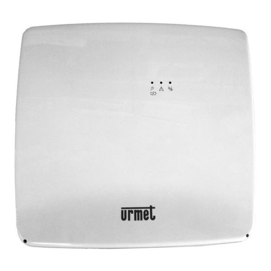
This chapter contains a description of the devices which allow to interact with the alarm system, to set or unset it and to program it. 1068/005A – 1068/010A CONTROL PANEL Figure 1 - 1068/005A – 1068/010A Control panel Ref. Description... -
Page 7: 1068/021 Lcd Command Keypad
Slow blinking: some zones assigned to the keypad defined as used are active, while the rest are SYSTEM STATUS inactive. Off: all Zones assigned to the keypad defined as used are inactive. (OK) To confirm the chosen menu and go to the submenu. Slider Key protection. Table 1 - 1068/021 keypad elements DS1068-045 LBT21166... -
Page 8: Status Icons In The Display
Reverse On: Consultation of details in progress ("ICON DETAILS" / "TAMPER” menu). Table 2 - LED and icon indications of 1068/021 keypad The indicated failures and warnings are: GSM/GPRS module, IP interface, power supply for overvoltage, power supply for low voltage, battery (inefficient or low battery), +V voltage of control panel and expansion inputs, intrusion alarm condition, input isolation or inhibition, tamper. -
Page 9: Zone Status
Zone status The zone status is shown on the keypad display in graphic mode. Figure 4 - Example 4-zones house - 1068/005A control panel Inside the house there is a square for each of the zones of the control panel. -
Page 10: 1068/027 Touch Screen Keypad
Each of the icons must maintain a state, indicated by a color change. For example gray if there is nothing to report and white if the user must be notified of at least one event of the respective class. Control panel status information bar Figure 5 - 1068/027 keypad status icons DS1068-045 LBT21166... - Page 11 Alarm events can be deleted. The page containing the list of tampering events is displayed. Tamper Tampering events can be deleted. Table 3 - 1068/027 Keypad icons By pressing on each single icon, information can be obtained. Power supply detail screen example: Selection indication Figure 6 –...
-
Page 12: 1067/334 - 1067/335 Electronic Key Reader
Slow blinking = open or inhibited/isolated inputs. 1067/334 – 1067/335 Shaped hole for inserting the electronic key. Keyhole for electronic key 1068/435 PROXIMITY KEY READER Figure 8 - 1068/435 proximity key reader Ref. Description Use or indications provided Off = all zones associated to the LED are unset. -
Page 13: System Basic Management
SYSTEM BASIC MANAGEMENT This chapter contains information for basic system management and describes how to activate and deactivate the system using keypads and electronic and proximity keys. IMPORTANT! Users and keys must have been previously acquired, configured and enabled to set and unset the system and to clear the alarms, as explained in paragraph 5.4 Enabling and disabling. -
Page 14: How To Set The Buzzer Volume
2.1.2 How to set the Buzzer volume Proceed as follows to adjust the Buzzer volume: Access the MASTER / INSTALLER / TECH. MANAGER / USER menu by entering the access code. Press to confirm; Select "Keypad settings" by pressing the key associated with the symbol. -
Page 15: Setting Procedure
You can activate the entire system and only a few zones if they have been configured in programming. The User or key must have been previously assigned to the zone during programming in order to operate on it. 2.3.1 Partial or total setting with 1068/021 keypad System setting can be: ... -
Page 16: Partial And Total Setting With Electronic Or Proximity Key
2.3.1.4 Quick partial setting To partially set the system zones using the shortcut keys, proceed as follows: Press the key associated with the symbol to activate the intrusion alarm system; Select, by pressing the keys ssociated with the symbols "A" / "B" / "C", the desired partial setting depending on the previous configuration. -
Page 17: Unsetting Procedure
You can unset the entire system and only a few zones if they have been configured in programming. The user or key must have been previously assigned to the zone during programming in order to operate on it. 2.4.1 Partial or total unsetting with 1068/021 keypad 2.4.1.1 Total unsetting... -
Page 18: Partial And Total Unsetting With Electronic Or Proximity Key
Unsetting from keypad under hold-up On the 1068/005A or 1068/010A control panel, if the hold-up function has been enabled if you are threatened and forced by a criminal and your life is at risk, then you can unset the intrusion alarm system while setting the hold-up alarm simultaneously, which will make the dialler send the programmed alarm messages without activating the siren sound. -
Page 19: System Status Information
SYSTEM STATUS INFORMATION 2.5.1 How to view system status The system status is displayed by the LED and summary synoptic provided on keypads and readers. The number of activated and assigned zones is shown on the keypad display. Each User can view the system status in detail for the part concerning to them (only the zones on which the user is authorised to operate will appear). -
Page 20: How To Examine The Tampers Memory
2.5.5 How to examine the Tampers Memory Tamper events are indicated by the specific LEDs (on keypad and readers) and stored by the control panel. Details on the events can then be viewed on the keypad display. Proceed as follows to view details: Press the key associated with the symbol to enter the menu;... -
Page 21: System Activation Failure
SYSTEM ACTIVATION FAILURE This chapter describes the causes that prevent the activation of the alarm system, indicating any remedies to be taken. An EN50131 compliant intrusion alarm system cannot be set by the User if certain blocking conditions are present. There are also conditions that can be inhibited which may be overridden and bypassed by means of specific manual commands imparted by the User or by the Installer. -
Page 22: Example Of Overriding
If the activation command is given by a control device other than a wired keypad, that is: Time scheduler Proximity key Electronic key Remote control Wireless keypad Key customised input GSM phone communicator ... -
Page 23: Alarms, Events And Indications
ALARMS, EVENTS AND INDICATIONS This chapter contains a detailed description of the alarms, events and signalling managed by 1068/005A and 1068/010A control panels. DESCRIPTION OF SIGNALLING EVENTS IN THE LOG The table below contains the messages that are displayed in the Log, the possible causes of the failure or malfunction that occurred, and actions to take to solve the problem. - Page 24 +V2 are correct. Faults A customised communicator fault input has been opened Available only with Communicators 1068/010A control panel. fault Faults An IP interface fault has been Perform the IP interface test detected to get any details about the...
- Page 25 --------------- --------------- factory settings. A customised fire reset input has Available only with M – I – T – U Fire Reset --------------- 1068/010A control panel. been opened A configuration backup has been Restoring --------------- --------------- restored. DS1068-045...
- Page 26 Description on Visible with Icon on Event Suggested actions System log code... keypad display Result of FW upgrade of the Check that the arrow next to devices the description is pointing upwards (positive result). If Update result --------------- the arrow points down (negative result), repeat the system upgrade procedure.
-
Page 27: Advanced System Management
ADVANCED SYSTEM MANAGEMENT This chapter contains information for complete system management including the procedures which are used less frequently than the system setting and unsetting procedures. SYSTEM ACCESS CODES Access to given system functions is permitted according to the access code type (Master, User, Installer or Technical Manager). The available codes are: Master code. -
Page 28: Default Access Codes
5.1.1 Default access codes The 1068/005A and 1068/010A control panels is provided with default codes when leaving the factory. The Installer and Technical Manager codes are enabled at the factory and automatically deactivated when a valid Master or User code is entered for the first time. -
Page 29: Menu
MENU All system configuration and enabling operations are performed using menus. The operations for accessing and navigating menus are described below. 5.2.1 How to access menus The menus can be accessed in two ways: By entering an access code (Master, Installer, User or Technical Manager), then The displayed menu will reflect the privileges of the access code used. -
Page 30: Free Access Menu
The various keys used to navigate the menus are shown in the following table. Description It identifies a parameter and activates and deactivates a certain function associated with the relevant symbol positioned above according to the scrolling menu. It confirms the entered access code, accesses the displayed submenu or confirms the selection made. It goes back to the previous page or menu level. -
Page 31: Main Menu
EN50131 Event (available only with 1068/010A control panel) SIM management System It allows you to set the expiry date of the SIM M - I - T - U Submenu M - I settings card used. -
Page 32: How To Enter Alphanumeric Characters
HOW TO ENTER ALPHANUMERIC CHARACTERS The keypad can be used to enter alphanumeric characters to store descriptive names for users, zones, outputs etc. Each name can be up to 24 characters long. Press the keys to select several characters cyclically as shown on the following table. A cursor will blink on the display at the entry point of the new character. -
Page 33: How To Enable The Installer
5.4.1 How to enable the Installer The Installer must have been previously enabled to work on the system. For safety reasons, Installer enabling is cancelled whenever a User or Master code is entered or when an electronic or proximity key, remote control or wireless keypad is used. IMPORTANT! The Installer is automatically enabled each time the system is turned on. -
Page 34: How To Enable A Key
5.4.4 How to enable a key Each key must have been previously enabled to work on the system. IMPORTANT! Each key must have been previously acquired to be enabled. Proceed as follows to enable a key: Access the MASTER menu by entering the access code. Press to confirm;... -
Page 35: Enabling Anti-Thieft Function
5.4.8 Enabling anti-thieft function Proceed as follows to enable the function anti-thieft: Access the MASTER menu by entering the access code. Press to confirm; Select "System Settings" by pressing the key associated with the symbol. Press to confirm; Select "Authorisations" by pressing the key associated with the symbol. -
Page 36: How To Disable Remote Access
5.4.15 How to disable remote access If you disable the remote access to the system, you will no longer be able to access the control panel via the "Urmet secure” and "Urmet 1068set" Apps. Proceed as follows to disable remote access to the system: Access the MASTER menu by entering the access code. -
Page 37: System Log
SYSTEM LOG 1068/005A Control panel The System Log stores the last 500 events (setting, unsetting, alarm, tamper etc.) which concerned the system. The events are stored from the most recent to the oldest, i.e. the most recent event is the one with the lowest identification number. -
Page 38: How To Interpret Viewed Data
5.5.3 How to browse the EN50131 Event Log (available only with 1068/010A control panel) Proceed as follows to browse the EN50131 Event Log: Enter the INSTALLER menu by entering the access code. Press to confirm;... -
Page 39: Users
USERS This chapter explains how to add new users. Adding a User essentially means configuring a “User” memory of the control panel, i.e. defining whether it is associated to the entire system or only to some zones and programming a descriptive name. The new user must be enabled after they have been created (see paragraph 5.4 Enabling and disabling). -
Page 40: Phone Dialer And Ip Interface
To enter and configure a phone number or IP address so that it can receive notifications; To write or delete the text that will be displayed in SMS messages (sending SMS requires the use of the 1068/458 module). ALARM AND EVENT NOTIFICATIONS Alarms and events can be reported via: Vocal calls to suitably configured phone numbers. -
Page 41: Phone Numbers And Ip Addresses
PHONE NUMBERS AND IP ADDRESSES The 1068 series control panels can store a directory of 12 elements. Each of these elements can be configured to contain either a phone number or an IP address. The configurations that can be modified for each of these 12 elements are as follows: The phone number or the IP address and port pair;... -
Page 42: Changing The Sending Mode
The networks that can be used are as follows: 1. GSM network. It requires the 1068/458 module and is compatible with vocal call, SMS, IDP call and IDP backup sending modes; 2. IP network. It requires the 1068/013 module and is compatible with IDP/IP call and IDP/IP backup sending modes. -
Page 43: Changing Events To Be Notified
SMS MESSAGES The 1068 series control panels can send SMS messages to the programmed telephone numbers when the following alarms or events occur. For each alarm or event it is possible to configure the descriptive text that will be added to the notification SMS. -
Page 44: User Remote Control
USER REMOTE CONTROL ACTIVATION AND DEACTIVATION OF OUTPUTS WITH SMS Outputs programmed as “commandable” can be activated or deactivated remotely by sending SMS messages. The "Incoming SMS" GSM parameter must be enabled to use this function. Furthermore, the text message must come from a known phone number, i.e. one of the 12 phone numbers stored on the control panel. -
Page 45: Remote Control With Guided Voice Menu
REMOTE CONTROL WITH GUIDED VOICE MENU The remote control call can be made from a landline with tone keypad (DTMF) or a mobile phone. The GSM answering machine must be enabled to uses all functions. If you want to use the GSM, you must program the parameter "Incoming GSM rings" to a value greater than zero. 8.4.1 Calling the GSM answering machine Call the GSM number of the control panel and wait for a number of rings equal to the value programmed for the parameter "Incoming... -
Page 46: List Of Dtmf Commands For Vocal Answer Machine
LIST OF DTMF COMMANDS FOR VOCAL ANSWER MACHINE Accepted DTMF key Function Action digits 01-04” Activation of entered zones followed by # (only if associated with the code used to access the answering machine). Zones setting Activation of all zones associated to the code. “01-04”... -
Page 47: System Test
IP interface Supplementary power supply battery (available only with 1068/010A control panel) Test the 1068 series system before prolonged absences, for example before the summer holidays. 9.1.1 Input test Proceed as follows to test that the inputs work perfectly: Access the MASTER / INSTALLER menu by entering the access code. -
Page 48: Control Panel Battery Test
9.1.3 Control panel battery test Proceed as follows to check the condition of the control panel battery: Access the MASTER / INSTALLER menu by entering the access code. Press to confirm; Select "System Settings" by pressing the key associated with the symbol. -
Page 49: Gprs/Gsm Field Test
9.1.8 Supplementary power supply battery test (available only with 1068/010A control panel) Proceed as follows to check the condition of the control panel battery: Access the MASTER / INSTALLER menu by entering the access code. Press to confirm;... -
Page 50: System Sheet
10 SYSTEM SHEET 10.1 INSTALLATION DETAILS Installation date Last name and first name Address Phone 10.2 ZONES TABLE Zone ID Zone description Notes DS1068-045 LBT21166... -
Page 51: Table Of Programmed Phone Numbers
10.3 TABLE OF PROGRAMMED PHONE NUMBERS Name Phone no. DS1068-045 LBT21166... -
Page 52: Quick Guide To Remote Control
11 QUICK GUIDE TO REMOTE CONTROL Cut out the following quick reference guides along the lines to keep the list of remote control commands handy at all times. The folded guide is credit-card-sized to conveniently fit in a wallet or purse. How to skip a telephone answering machine Guided voice menu Call the control panel from a DTMF tone phone. - Page 53 Cut out the following quick reference guides along the lines to keep the list of remote control commands handy at all times. The folded guide is credit-card-sized to conveniently fit in a wallet or purse. How to skip a telephone answering machine Guided voice menu Call the control panel from a DTMF tone phone.
- Page 54 Cut out the following quick reference guides along the lines to keep the list of remote control commands handy at all times. The folded guide is credit-card-sized to conveniently fit in a wallet or purse. How to skip a telephone answering machine Guided voice menu Call the control panel from a DTMF tone phone.
- Page 55 DIRECTIVE 2012/19/EU OF THE EUROPEAN PARLIAMENT AND OF THE COUNCIL of 4 July 2012 on waste electrical and electronic equipment (WEEE) The symbol of the crossed-out wheeled bin on the product or on its packaging indicates that this product must not be disposed of with your other household waste.
- Page 56 DS1068-045 LBT21166 Area tecnica URMET S.p.A. servizio clienti +39 011.23.39.810 10154 TORINO (ITALY) http://www.urmet.com VIA BOLOGNA 188/C e-mail: info@urmet.com Telef. +39 011.24.00.000 (RIC.AUT.) +39 011.24.00.300 - 323 MADE IN CHINA DS1068-045 LBT21166...
Need help?
Do you have a question about the 1068 and is the answer not in the manual?
Questions and answers