urmet domus 1068 Installation And Configuration Manual
Hide thumbs
Also See for 1068:
- Installation and programming manual (152 pages) ,
- User manual (56 pages) ,
- Quick manual (40 pages)
Table of Contents
Advertisement
Quick Links
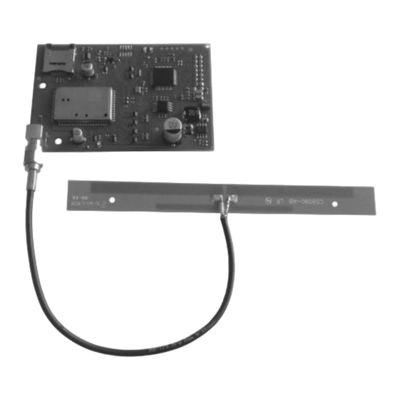
DS1068-025A
RADIO MODULE
Ref. 1068/011
Through the following QR Code, it is possible to download the eventual new version of the manual.
http://qrcode.urmet.com/default.aspx?prodUrmet=141749&lingua=en
1068/011
http://qrcode.urmet.com/default.aspx?prodUrmet=156690&lingua=en
INSTALLATION AND CONFIGURATION MANUAL
RADIO INTERFACE ON BUS
Ref. 1068/017
Mod.
1068
LBT20788
1068/017
Advertisement
Table of Contents

Related Manuals for urmet domus 1068


Summary of Contents for urmet domus 1068
- Page 1 Mod. 1068 DS1068-025A LBT20788 RADIO MODULE RADIO INTERFACE ON BUS Ref. 1068/011 Ref. 1068/017 Through the following QR Code, it is possible to download the eventual new version of the manual. http://qrcode.urmet.com/default.aspx?prodUrmet=141749&lingua=en 1068/011 http://qrcode.urmet.com/default.aspx?prodUrmet=156690&lingua=en 1068/017 INSTALLATION AND CONFIGURATION MANUAL...
-
Page 2: Table Of Contents
Positioning the system devices ..........................14 INSTALLATION ................................. 14 Installation procedure ............................ 14 5.1.1 Assembly of the 1068/011 in the control units 1068 series ..................14 5.1.2 Installation of the 1068/017 radio interface ......................15 Radio interface connections 1068/017 ......................16 5.2.1... - Page 3 1068/017 Radio interface inputs ..........................35 9.8.3 Radio expansions outputs (sirens) ......................... 35 TECHNICAL SPECIFICATIONS ..........................36 10.1 1068/011 Radio module ..........................36 10.2 1068/017 Radio interface on bus ........................36 10.3 1051/025 Led keypad ............................ 36 10.4 1051/035 Remote control ..........................36 DS1068-025A LBT20788...
- Page 4 1051/101 – 1051/102 IR detector standard version and with pet immunity function ........37 10.5 10.6 1051/103 Internal IR detector dual technology ..................... 37 10.7 1051/105 external IR detector with pet immunity function ................37 10.8 1051/107 external IR detector dual technology with pet immunity function ..........37 10.9 1051/108 IR detector curtain effect .......................
-
Page 5: 1068/011 And 1068/017 For 1068 System Series
If you use the control panel: 1068/005, you can only install 1 interface in place of 1068/011 radio module 1068/010, the maximum number between interface and modules is 2 (example: 1 module and 1 interface or 2 interfaces). DS1068-025A LBT20788... -
Page 6: System Components
4 radio keypads. Before using the module remember to enable it, as it is disabled by default. For radio devices that can be combined to the 1068/011 radio module, please see the Urmet catalogue. 1.3.2 1068/017 Radio interface on Bus Optional radio interface that makes it possible to integrate, radio devices as infrared detectors, magnetic contacts, sirens, remote controls radio keypads in the wired 1068 control panels series. -
Page 7: 1051/025 Led Keypad
1.3.3 1051/025 Led Keypad The Led keypad is powered by a lithium battery and communicates via radio both with the Ref. 1068/011 module and with the ref. 1068/017 interface in bidirectional mode. It has 4 function keys, three keys for the arming and disarming of associate zones and one key for the system status. -
Page 8: 1051/103 Dual Technology Indoor Ir Detector
PIR as initial detection and of microwaves for confirmation before sending the alarm signal. It is powered by a lithium battery and communicates via radio both with the Ref. 1068/011 module and with the ref. 1068/017 interface in bidirectional mode. -
Page 9: 1051/108 Ir Detector Curtain Effect
The detector is designed to work within a detection field of 8 metres. It is powered by a lithium battery and communicates via radio both with the Ref. 1068/011 module and with the ref. 1068/017 interface in bidirectional mode. -
Page 10: 1051/203 Multifunction Magnetic Contact
(use of wire contacts for rolling blinds Urmet Ref. 1033/207 is recommended). It is powered by a lithium battery and communicates via radio both with the Ref. 1068/011 module and with the ref. 1068/017 interface in bidirectional mode. -
Page 11: Basic Information
BASIC INFORMATION HOW AN INTRUSION RADIO ALARM SYSTEM AND BUS IS MADE 2.1.1 Radio and Bus system This main distinction between installations is based on the technology used to connect the various devices to the control panel and each other. The radio system connection is also called wireless. Pros Cons Requires no wiring: all communications occur via radio and... -
Page 12: Command Devices
The remote control is powered by a CR2032 3 V lithium battery. Battery housing In order to use the remote control, the 1068/011 radio module must be installed in the control unit or there must be a connection via Bus via the 1068/017 interface. -
Page 13: 1051/025 Led Keypad
1051/025 LED KEYPAD Figure 2 - 1051/025 Led keypad Ref. Description Use or indications provided Green LED on: the system is in Test mode. Green LED blinking: in Test mode, this indicates flat battery. Keypad state LED Orange LED on for 5 seconds: the system is in normal operating mode. (Green/Orange) ... -
Page 14: Design: Configuration Of The Alarm System
4.1.1.1 Positioning of the radio modulo 1068/011 If the radio module is used, the connection inside the 1068 control unit series is via a dedicated connector. IMPORTANT! The installation of the radio module results in the loss of EN50131 certification. -
Page 15: Installation Of The 1068/017 Radio Interface
5.1.2 Installation of the 1068/017 radio interface The 1068/017 radio interface is supplied with a plastic case. The interface has terminals for connecting it to the data BUS and the LEDs that signal the functioning of the electronic board. The tamper of the container must be connected to the SAB of the expansion. -
Page 16: Radio Interface Connections 1068/017
RADIO INTERFACE CONNECTIONS 1068/017 Below is an explanation on how to carry out all the electrical connections and necessary signals for starting up the system. IMPORTANT! Before running the cables, check that the sections are correct and that conform to the maximum distances. -
Page 17: Commissioning
COMMISSIONING NAVIGATION MENU WITH 1068/021 KEYPAD Programming is carried out using the keys and reading the messages and information which appear on the display. WARNING! The keys are associated with the respective symbols located above and shown on the display. -
Page 18: Enabling/Disabling The 1068/011 Radio Module
ENABLING/DISABLING THE 1068/017 RADIO INTERFACE Compared to the 1068/011 radio module, the 1068/017 radio interface cannot be enabled or disabled. It is automatically enabled when it is acquired on the bus and disabled when deleted. -
Page 19: Maintenance
Press to confirm; In presence of a Fieldbus module, you will be asked which type of expansion you want to work on (1068/011 or 1068/017), vice versa no; Select “Input devices” or “Dispositivi Output devices” by pressing the key associated with the symbol. -
Page 20: Replacing A Radio Device
REPLACING A RADIO DEVICE It allows you to replace a device by assigning to the new one the same address and configuration of the previous one. To replace a device, follow the instructions below: Enter the INSTALLER menu by entering the access code. Press to confirm;... -
Page 21: Deleting A Radio Device
Physically disconnect the interface from the bus and/or the module from the control panel; Then power up the system again. If the control panel is powered again without disconnecting the 1068/011 module from the control panel, the module is automatically acquired upon restart. -
Page 22: Radio Connection Test
RADIO CONNECTION TEST The 1068/011 radio module or the 1068/017 radio interface allow it possible to evaluate the quality of the radio connection between the peripheral devices subject to supervision through an integrated test that provides an indication correlated to the power of the signal measured by each single device. -
Page 23: Configuring Radio Parameters
CONFIGURING RADIO PARAMETERS The paragraphs below describe the steps to change the default configuration of the module parameters or the radio interface. 7.9.1 Devices supervision Enter the INSTALLER menu by entering the access code. Press to confirm; Select "System Settings" by pressing the key associated with the symbol. -
Page 24: Enable (Available Only With 1068/011 Radio Module)
10. Press to return to the upper level menu. 7.9.4 Module supervision (Available only with 1068/011 radio module) Enter the INSTALLER menu by entering the access code. Press to confirm; Select "System Settings" by pressing the key associated with the symbol. -
Page 25: System Commissioning
IMPORTANT! Remember that the maximum number of inputs can managed by the 1068/005 control panel is 21, while for the 1068/010 control panel it is 66. All control panel and expansion unit inputs are configured by default, while the auxiliary inputs of keypads and input 2 of the readers are NOT USED by default. -
Page 26: Zone Assignment Type (And / Or)
8.1.6 Zone assignment type (AND / OR) The operation of the intrusion inputs may be customised further by setting the attributes (see dedicated paragraph in the control unit manual). 8.1.7 AND inputs It logically connects two intrusion / instantaneous / pre-alarm / path inputs with the same customisation, the same associated zones and the same zone association. -
Page 27: Radio Output Programming
The radio outputs are available only if the radio module or the radio interface is installed. Both the 1068/011 radio module and the 1068/017 radio interface can manage up to four radio sirens. There are no other radio output types. -
Page 28: Radio Output Encoding
UY: → where: dd is the type of radio device assigned to an 1068/011 module or an 1068/017 interface, XX is the sequential number of the radio devices acquired as outputs, Y is the number of the XX radio device output (physical address), ... -
Page 29: 1051/035 Remote Control Programming
13. Select “Status report” by pressing the key associated with the symbol. Press to confirm; Visual Audible/visual Disabled 14. Press to return to the upper level menu; 15. Select “Other parameters” by pressing the key associated with the symbol Press to confirm;... -
Page 30: Programming Partialization Key
8.3.3 Programming partialization key Proceed as follows to program the PARTIALIZATION KEY: Enter the INSTALLER menu by entering the access code. Press to confirm; Select "System Settings" by pressing the key associated with the symbol. Press to confirm; Select "Programming" by pressing the key associated with the symbol. -
Page 31: 1051/025 Keypad Programming
1051/025 KEYPAD PROGRAMMING 8.4.1 Programming setting key Proceed as follows to program the SETTING KEY: Enter the INSTALLER menu by entering the access code. Press to confirm; Select "System Settings" by pressing the key associated with the symbol. Press to confirm; Select "Programming"... -
Page 32: Programming Function Key
8.4.4 Programming function key Proceed as follows to program the FUNCTION KEY: Enter the INSTALLER menu by entering the access code. Press to confirm; Select "System Settings" by pressing the key associated with the symbol. Press to confirm; Select "Programming" by pressing the key associated with the symbol. -
Page 33: System Commissioning
SYSTEM COMMISSIONING SETTING USING 1051/035 REMOTE CONTROL 9.1.1 Total setting The remote control must have been duly programmed for all zones to set all the zones in the system. Press the on the remote control to set all zones. If the control unit has accepted the command, the LED will light up red and then green. -
Page 34: Unsetting Using 1051/025 Keypad
… Name Logical address IN01… IN28 DC01… DC28 Physical address IR01… IR28 IMPORTANT! Remember that the maximum number of inputs can managed by the 1068/005 control panel is 21, while for the 1068/010 control panel it is 66. DS1068-025A LBT20788... -
Page 35: 1068/017 Radio Interface Inputs
IN01… IN28 DC01… DC28 Physical address IR01… IR28 IMPORTANT! Remember that the maximum number of inputs can managed by the 1068/005 control panel is 21, while for the 1068/010 control panel it is 66. 9.8.3 Radio expansions outputs (sirens) Status report... -
Page 36: Technical Specifications
Number of radio channels ..................................1 Relative operating humidity ................................75% Operating temperature ............................... -20°C ÷ +50°C 10.2 1068/017 RADIO INTERFACE ON BUS Nominal power voltage ..........................13.8 V⎓ (taken with the bus) Operating voltage ................................9 V⎓ ÷ 15 V⎓... -
Page 37: 1051/101 - 1051/102 Ir Detector Standard Version And With Pet Immunity Function
10.5 1051/101 – 1051/102 IR DETECTOR STANDARD VERSION AND WITH PET IMMUNITY FUNCTION Communication technology ..........................Two-way radio frequency Frequency ....................................868 MHz Power supply ..............................1 Battery 3V type CR123A Battery life ....................... 5 years (Typical value, may vary depending on use) Infrared range ...................... -
Page 38: 1051/108 Ir Detector Curtain Effect
10.9 1051/108 IR DETECTOR CURTAIN EFFECT Communication technology ..........................Two-way radio frequency Frequency ....................................868 MHz Power supply ..............................1 Battery 3V type CR123A Battery life ......................3 years (Typical value, may vary depending on use)) Infrared range ............................... 8m (max) with angle of 110° Detecting elements A: vertical assembly on wall Curtain coverage range of 8 m, installed between 1.4 and 1.7 m from the floor. -
Page 39: 1051/201 - 1051-202 Magnetic Contact
10.10 1051/201 – 1051-202 MAGNETIC CONTACT Communication technology ..........................Two-way radio frequency Frequency ....................................868 MHz Power supply ..............................1 CR2 Lithium 3V battery Battery life ......................10 years (Typical value, may vary depending on use) Operating temperature ............................... -10°C ÷ +45°C Dimensions .................................. - Page 40 DS1068-025A LBT20788 Area tecnica URMET S.p.A. servizio clienti +39 011.23.39.810 10154 TORINO (ITALY) http://www.urmet.com VIA BOLOGNA 188/C e-mail: info@urmet.com Telef. +39 011.24.00.000 (RIC.AUT.) +39 011.24.00.300 - 323 MADE IN TAIWAN DS1068-025A LBT20788...
Need help?
Do you have a question about the 1068 and is the answer not in the manual?
Questions and answers