
Subscribe to Our Youtube Channel
Related Manuals for marposs P3UP


Summary of Contents for marposs P3UP
- Page 1 Measurement system for grinding machines INSTALLATION AND USER MANUAL Manual code: D2P30002GF...
- Page 2 About the Directive “RoHS” regulating the presence of certain hazardous substances in Marposs electrical and electronic equipment, refer to http://www.marposs.com/compliance_detail.php/eng/rohs About possible use in Marposs products of materials coming from conflict areas, refer to: http://www.marposs.com/compliance_detail.php/eng/conflict_minerals INFORMATION FOR USERS concerning the terms of the National Legislation enforcing the Directive 2012/19/EU on waste electrical and electronic equipment (WEEE).
- Page 3 REVISION 11/2017 MARPOSS S.p.A. does not undertake any obligation of notifying possible changes to the product. The descriptions reported in this manual do not authorise any tampering by non-authorised personnel. The warranty on the equipment will decay if such tampering is found.
- Page 4 2.1.4 PERSONAL PROTECTION EQUIPMENT (PPE) 2.1.5 GENERAL INFORMATION 2.1.5.1 Operator's position 2.1.5.2 Operator's tasks 2.1.5.3 Training 2.1.5.4 Procedures 2.2 P3UP SAFETY INFORMATION 2.2.1 AUTHORISED AND UNAUTHORISED USAGE. 2.2.1.1 Authorised usage 2.2.1.2 Unauthorised usage 2.2.2 RISKS, PROTECTION, WARNINGS AND CAUTIONS 2.2.2.1 Residual risks 3.
-
Page 5: Table Of Contents
4.1.1.4 Humidity 4.1.1.5 Altitude 4.1.1.6 Contaminating agents 4.1.1.7 Ionizing and non-ionizing radiation 4.1.1.8 Lighting of a 'normal' environment 4.1.1.9 Removing the P3UP from its packaging 5. GENERAL EQUIPMENT DESCRIPTION 5.1 PRODUCT VERSIONS 5.2 DESCRIPTION OF CONNECTORS 5.3 GENERAL TECHNICAL SPECIFICATIONS 5.4 THE PROCESS MEMORIES... - Page 6 7.3.2.11 RET t1 and RET t2 (optional) 7.3.2.12 A M SAFE 7.3.2.13 DEFAULT 7.3.2.14 P3UP VERSION 7.3.2.15 DISPLAY 7.3.3 SETTING UP THE PROGRAMMING PARAMETERS (P3UP WITH MEMORY) 7.3.3.1 Damping Memory 7.3.3.2 Continuous sampling memory 7.3.3.3 Memory for planes 7.3.3.4 Stock removal estimate memory 7.3.4 CLOSING THE PROGRAM MENU...
- Page 7 GENERAL INFORMATION 1.1 Foreword The P3UP is designed and constructed to be installed in machines such as grinders as a machining control accessory. The P3UP must be installed in accordance with the instructions provided in this manual and shall not conform to the European standards and directives listed on page 2 unless these conditions are fulfilled.
- Page 8 Electric shock hazards may be present when carrying out fault finding routines on live components. FIRE OR EXPLOSION RISK The P3UP cannot be used in location with the risk of explosion and/or fire (the P3UP is not certified pursuant to directive 94/9/EC ATEX). DANGER OF CRUSHING Proceed with caution when moving or handling the P3UP.
- Page 9 All the data listed on the plate must always be legible. If a data plate is damaged or even partially illegible due to wear, ask MARPOSS for another one, quoting the data in these instructions or on the original data plate.
- Page 10 2.1.3.2 State of health of the operator/installer The operator assigned to install the P3UP must be aware and responsible of the dangers that may be generated during the installation of machining equipment.
- Page 11 Installation and User Manual 2.1.4 Personal Protection Equipment (PPE) The operators assigned to assemble and maintenance of the P3UP must use the following personal protection equipment: Gauge assembly operator: PROTECTIVE CLOTHING PROTECTIVE FOOTWEAR PROTECTIVE GLOVES Gauge/final machinery operating operator: The operator does not require particular PPE, apart from that required in the work environment, to operate the gauge.
- Page 12 The P3UP is designed and constructed to interlock with a machine, of which it becomes to all intents and purposes, a sub-assembly. Therefore refer to the final machine that the P3UP will be installed in for the operator’s position during all the various operation processes, in particular during production and maintenance.
- Page 13 Marposs, in order to prevent the risks associated with moving loads; • Ensure they are aware of the correct storage procedures for the parts of the P3UP in order to prevent damaging important parts, not only in terms of safety but also from an operational point of view;...
- Page 14 2.2.1 Authorised and unauthorised usage. 2.2.1.1 Authorised usage The P3UP has been designed and built to be installed on automatic machines such as grinders in order to manage the Marposs measurement heads used for in-process part dimension controls. N.B. Any use that differs from the use described above is considered unintended.
- Page 15 Due to the type of construction it is not possible to guarantee absolute safety against risks and dangers generated by: Operator carelessness, • • Non-compliance with the information and indications contained in these instructions, • Deliberately tampering with the P3UP and/or its safety devices, • Tampering with the fixed and movable safety panels.
- Page 16 The operators assigned to the transport, storage and installation of the P3UP must be provided with and use the PPE indicated in section 0, as well as the obligatory PPE for the environment that the P3UP is used in. 3.1.2...
- Page 17 The P3UP must be stored in covered premises with limited exposure to dust and humidity. The warehouse flooring must be horizontal and free of irregularities. Do not position other materials, even light items, on top of the P3UP package or the P3UP itself, in order to avoid damaging it.
-
Page 18: General Information
4.1.1.1 Type of environment The P3UP and the relative electrical components have been designed and constructed to be installed in an industrial plant and to be used only in closed environments where they cannot be subject to atmospheric agents. -
Page 19: Contaminating Agents
4.1.1.9 Removing the P3UP from its packaging Marposs has not stipulated and special equipment to be used when removing the P3UP from its packaging. The operator must proceed carefully and avoid carrying out any actions that might damage the P3UP or any of its components. -
Page 20: General Equipment Description
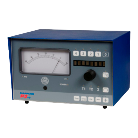
Installation and User Manual GENERAL EQUIPMENT DESCRIPTION The P3UP connected to the Marposs measurement heads can be used to check the dimensions of the part in the machine and display the state of the machining process. The value of the measurement during the grinding process is compared with the pre-defined stock metal values, thus providing the machine with the signals it requires in order to control the progress of the grinding wheel. - Page 21 Installation and User Manual Figure 3: P3UP case version Figure 4: P3UP panel mounted version...
-
Page 22: Description Of Connectors
* Use Marposs measurement head switch connectors W1 and W2. N.B. P3UP WITH CASE: Position the unit so that it is not difficult to remove the due power supply connectors (A and H1 in Figure 5: P3UP rear view) PANEL MOUNTED P3UP: Must be fitted with a switching device that can be used to isolate the unit from its two power supplies A and H1 in fig Figure 5: P3UP rear view). -
Page 23: General Technical Specifications
Table 5-1 P3UP technical specifications STRUCTURE Case or panel mounted 1 or 2 channels CHANNELS For connection to Marposs LVDT or Air-Gap type measurement heads with or without retraction MEASURING CYCLES In-process grinding checks According to dial indicator scale: 100-0-20 (+1000 to -200 μm) -
Page 24: The Process Memories
(e.g. reciprocating internal applications). Refer to the specific documentation for the P3UP in order to check the type of memory installed in the unit, if present. -
Page 25: Installation Procedure
INSTALLATION PROCEDURE To install the unit, proceed as follows: Secure the P3UP to the machine tool (see para.6.1) Connect the measurement heads to the connectors on the rear of the unit. (see para. 6.2) Connect the I/O connector to the machine logic (see para.6.3). -
Page 26: Securing The Unit To The Machine Tool
Installation and User Manual 6.1 Securing the unit to the machine tool In the case of the P3UP version with case, secure the gauge to the machine tool using the four internally threaded feet (M4 thread). 20.7 Figure 7: P3UP external dimensions in mm, case and panel-mounted versions In the case of the P3UP panel mounted version, use the M3 threaded pins positioned on the rear of the panel. - Page 27 Installation and User Manual WARNING The P3UP panel version must be fitted with a fire-resistant casing. The machine panel itself may act as this casing, provided it conforms to the specifications required by the standard EN61010- 1 regarding fire-resistant casings.
- Page 28 Figure 10: External dimensions diagram – Bracket version 2/2 N.B. If necessary, a mounting bracket is available for the P3UP Bracket mounting instructions: 1. Disconnect the power supply lead and the machine I/O cable in order to ensure that the unit is de- energised.
-
Page 29: Connecting The Measurement Heads
Installation and User Manual 6.2 Connecting the measurement heads The unit can be connected to Marposs In-Process heads with one or two transducers. The following connections are available, depending on the requirements of the application. P3UP In Process version... -
Page 30: I/O Connection To The Machine Logic
Installation and User Manual 6.3 I/O connection to the machine logic The P3UP gauge may be fitted with various types of machine I/O: “I/O TYPE A” relays outputs with N.A. contact (normally open) “I/O TYPE B” Opto-isolated “I/O TYPE C” Outputs with exchanged relays;... -
Page 31: I/O Type A - Outputs With N.o. Contacts Relays
Installation and User Manual 6.3.1 I/O TYPE A – Outputs with N.O. contacts relays The following table lists the variants that are available: label Input nominal voltage Output voltage I/O TYPE A1 24 V a.c. / d.c max 150 V a.c. I/O TYPE A2 115 V a.c. - Page 32 Installation and User Manual INPUTS OUTPUTS “I/O TYPE A1” or I/O TYPE A5” variants "I/O TYPE A1" variant Are equipped with 24 V d.c. or 24 V a.c. r.m.s. drivable Relay with N.O. contact (Normally Open = closed inputs, the difference between the two versions is when active) explained below.
- Page 33 Installation and User Manual "I/O TYPE A5" and "I/O TYPE A6" variants "I/O TYPE A2" and "I/O TYPE A6" variants • Relay with N.O. contact (Normally Open = closed These two variants feature 115 V a.c. (sinusoidal) drivable when active) inputs: •...
- Page 34 3.2. mm; connect the shield (P3UP side) to the case of the Heavy Duty connector and to the chassis on the machine side using suitable terminal blocks or metallic cable clamps. Make sure that the contact surface between the shields and the machine chassis is ample, free from surface insulation (e.g.
- Page 35 Installation and User Manual H1 connector pin-out I/O signal connections TERMINAL SIGNAL DESCRIPTION The input circuits drive voltage supply must be applied between this terminal (inputs common) and each individual terminal in use (via a INPUT COMMON micro-switch or similar device). The Start Cycle signal is connected to this terminal Remove the power supply to this terminal to enable measurement system during -START CYCLE...
-
Page 36: I/O Type Aa - Outputs With N.o. Contacts Relays
Installation and User Manual 6.3.2 I/O TYPE AA – Outputs with N.O. contacts relays H1 connector wiring diagram for I/O TYPE AA User’s logic (ex.CNC,PLC,etc.) P3UP INPUTS COMMON Inputs power START CYCLE supply INPUTS MEMORY HOLD HEAD RETRACTION +24 Vnst Ref. - Page 37 3.2. mm; Connect the shield (P3UP side) to the case of the Heavy Duty connector and to the chassis on the machine side using suitable terminal blocks or metallic cable clamps. Make sure that the contact surface between the shields and the machine chassis is ample, free from surface insulation (e.g.
- Page 38 Installation and User Manual H1 connector pin-out I/O signal connections TERMINAL SIGNAL DESCRIPTION The input circuits drive voltage supply must be applied between this terminal (inputs common) and each individual terminal in use INPUT COMMON (via a micro-switch or similar device). The Start Cycle signal is connected to this terminal Remove the power supply to this terminal to enable measurement system -START CYCLE...
-
Page 39: I/O Type B - 24V D.c. Opto-Isolated Type Machine I/O
Installation and User Manual 6.3.3 I/O TYPE B – 24V d.c. opto-isolated type machine I/O H1 connector wiring diagram for I/O TYPE B P3UP User’s logic (ex.CNC, PLC, etc.) INPUTS COMMON Inputs power supply START CYCLE MEMORY HOLD INPUTS HEAD RETRACTION PULSE FEEDBACK + (*) PULSE FEEDBACK –... - Page 40 I/O cables that exceed 30 m in length it is necessary to use shielded cable. Use a globally shielded cable with the braid connected to the case of the Heavy Duty connector (P3UP connection) and to the machine chassis at the other end by means of suitable terminal block or metallic cable clamp.
- Page 41 Installation and User Manual H1 connector pin-out I/O signal connections TERMINAL SIGNAL DESCRIPTION The input circuits drive voltage supply must be applied between this terminal (inputs common) and each individual terminal in use INPUT COMMON (via a micro-switch or similar device). The Start Cycle signal is connected to this terminal Remove the power supply to this terminal to enable measurement system -START CYCLE...
-
Page 42: I/O Type C - Outputs With Exchanged Relays
Installation and User Manual 6.3.4 I/O TYPE C – Outputs with exchanged relays H1 connector wiring diagram for I/O TYPE C1 P3UP User’s logic (ex.CNC, PLC, etc.) INPUTS COMMON START CYCLE INPUTS MEMORY HOLD HEAD RETRACTION OUTPUTS Example of C2... - Page 43 3.2 mm; 5. connect the shield (P3UP side) to the case of the Heavy Duty connector and to the chassis on the machine side using suitable terminal blocks or metallic cable clamps. Make sure that the contact surface between the shields and the machine chassis is ample, free from surface insulation (e.g.
- Page 44 3.2 mm; connect the shield (P3UP side) to the case of the Heavy Duty connector and to the chassis on the machine side using suitable terminal blocks or metallic cable clamps. Make sure that the contact surface between the shields and the machine chassis is ample, free from surface insulation (e.g.
- Page 45 Installation and User Manual H1 connector pin-out I/O signal connections TERMINAL SIGNAL DESCRIPTION The input circuits must be driven leaving each individual terminal in INPUT COMMON use free or connecting them to this terminal (inputs common). The Start Cycle signal is connected to this terminal Leave this terminal free in order to enable measurement system during -START CYCLE working cycle.
-
Page 46: Connecting The Analogue Output
Maximu permissible load resistance: 10kΩ Use a globally shielded (max 10 m) cable with the braid connected to the case of the connector (P3UP connection) and to the machine chassis at the other end by means of suitable terminal block or metallic cable clamp. - Page 47 Installation and User Manual The number of wires used must be the same as the number of analogue outputs that are effectively in use: One wire for the analogue output and one wire for the corresponding return signal. The cross section of the wires must be at least 0.08 mm SIGNAL DESCRIPTION NOTES...
-
Page 48: Power Supply And Earth Connections
• The machine outputs (see section 6.3) may change state. • When using measurement heads equipped with a P3UP operated finger opening (retraction) system, this may not function correctly (e.g. it may not be possible to open the fingers if they are closed, or close them if they are open). -
Page 49: Switching The Unit On
In the case of the panel mounted version, secure the P3UP to a metal panel on the machine that is connected to the centre of mass of the machine (which is, in turn, connected to earth), using the pins present on the rear of the P3UP front panel. -
Page 50: Measurement Head Mechanical Zero-Setting
Installation and User Manual 6.7 Measurement Head Mechanical Zero-Setting Mechanically zero-set the measurement heads with P3UP in MANUAL MODE. The individual In-Process measurement head channels can be displayed by selecting channel T1 or T2 6.7.1 Mechanical zero-setting In-Process heads with adjustment guides Measurement head with two ball probes •... - Page 51 Installation and User Manual Measurement head with two bar probes • Head Support Unit Figure 14: Measurement head with two bar probes Unimar Measurement heads with bar probes • Head Support Unit Figure 15: UNIMAR measurement heads with bar probes •...
- Page 52 Installation and User Manual Head support – Slide with Head support – Slide with retaining screws locking handle Loosen screws 5 maintaining the friction on them. Release the movement of the head support by adjusting the handle 5b. Adjust screws 5a so as to allow frictioned movement of the head support.
-
Page 53: Mechanical Zero-Setting In-Process Heads With Latches
Installation and User Manual 6.7.2 Mechanical zero-setting In-Process heads with latches • Measurement head with two probes Head Support Unit Figure 16: Measurement head with two probes Unimar measurement heads • Head Support Unit Figure 17: UNIMAR Measurement Heads... - Page 54 Installation and User Manual • Measurement head diameter alignment (Refer to the examples in Figure 16: Measurement head with two probes and Figure 17: UNIMAR Measurement Heads) Place a ground workpiece in the spindle or between the tips. Loosen screws 1 and 3 to allow a frictioned movement of the contact tips 2 and 4. Rotate contact tips 2 and 4 moving them to a position where it is possible to insert the head in the measurement position in safely (without impacting the part).
-
Page 55: Fast Zero-Setting Unimar In-Process Heads With Locking Lever
Installation and User Manual 6.7.3 Fast zero-setting Unimar In-Process heads with locking lever Supporto frizionato (Τ) To make it easy to assemble the frictioned support and to adjust the rapid zero-setting units correctly (lever B and corresponding stop dowel) refer also to document "UNIMAR – Swing bracket application"... - Page 56 Installation and User Manual Head support – Slide with Head support – Slide with retaining screws locking handle Loosen screws 5 maintaining the friction on them. Release the movement of the head support by adjusting the handle 5b. Adjust screws 5a so as to allow frictioned movement of the head support.
-
Page 57: Mechanical Zero-Setting In-Process Heads With Wemar Type Support
Installation and User Manual 6.7.4 Mechanical zero-setting In-Process heads with WEMAR type support Figure 19: Mechanical zero-setting with WEMAR type support • Measurement head diameter alignment (Refer to the layout of Figure 19: Mechanical zero-setting with WEMAR type support) Place a ground workpiece either on the spindle or between the centers. Loosen screws 1 and 3 so as to allow frictioned movement of screws 2 and 4 (fractioned head movement on support). - Page 58 Installation and User Manual • Adjusting the Upper Contact (Refer to the layout of Figure 19: Mechanical zero-setting with WEMAR type support) Loosen screw 1 maintaining the friction on it. Rotate the screw 2 so that the upper contact touches the master workpiece and the measurement value that appears on the gauge is around zero (±...
-
Page 59: Cyclograms
Installation and User Manual 6.8 Cyclograms The following is a typical cyclogram for P3UP with In-Process measurements The cyclograms may vary, depending on the application, consult the documentation supplied with the unit. -
Page 60: Operating And Using The Device
The P3UP has two operating conditions: P3UP in measurement: The unit is in this operating condition when it is not being set-up (see para. 7.2) P3UP in set-up: The unit is in this operating condition when the user accesses the programming menu (see para. - Page 61 Installation and User Manual Tabella 71: Description of the P3UP panel Reference Description Analogue measurement display instrument. The following types are available: • 50-0-10 (x1 / x10) μm White • 100-0-20 (x1 / x10) μm White • 10-0-2 (x1 / x10) μm White •...
-
Page 62: Mechanical Zero-Setting The Instrument
When in measurement mode, wait for three seconds after applying the last modification to one of the data listed above before switching the unit off. The P3UP memorises the state of the panel three seconds after the last time it is used. -
Page 63: Tip Mode
Installation and User Manual 7.2.2 TIP Mode This optional function is available for the In-Process cycle. In TIP mode it is possible to deactivate the C1 grinder advance control manually, if it has been triggered. The control is deactivated by pressing button “4” on the panel and lasts only as long as button “4”... -
Page 64: Zero Adjust
Installation and User Manual 7.2.4 Zero adjust The InProcess measurement can be corrected in two ways: ZADJ Manual Zero Adjust Automatic Zero Adjust ZERO ZADJ MODE To access the Zero Adjust (ZADJ) mode, press the knob (the operator may not be able to access the zero adjust during the cycle in automatic mode, see description in para. - Page 65 Then ADJ RNG and ±500 µm appears on the display. If the zero is not executed the P3UP displays the message ZERO OVR ADJ RNG ±500 µm ZERO OVR on the display and sets the maximum correction possible (±...
-
Page 66: Pulse Feedback
The correction value (+) or (-) may be derived from the machine logic via two dedicated external signals at the P3UP input (see para. 0). It is not possible to use the I/O signals for the correction value when the P3UP is in the alarm condition or manual programming state. -
Page 67: Description Of The Memory Functions
Description of the memory functions The memory is installed on the P3UP in order to guarantee stable results when monitoring the machining process even when working on parts without smooth surfaces (e.g. parts with keyslots) or when it is not possible to maintain the measurement head permanently in contact with the part (e.g. -
Page 68: Continuous Sampling Memory
I/O functions. AUTOMATIC The memory is active. Disable The P3UP must be in manual mode in order to disable the memory. I/O input The lock measurement signal is always available from the I/O MEMORY CONTROL ON: the memory freezes the acquired measurement value... -
Page 69: Memory For Planes (With Internal Synchronisation)
7.2.6.5 Memory for planes (with internal synchronisation) The memory is used for P3UP when installed on surface grinding machines in order to control the part surface or its distance from a reference plane. The P3UP processes the measurement at regular intervals as set-up during the programming phase. -
Page 70: Stock Removal Estimate Memory
AUTOMATIC The memory is active. Disable It is possible to disable the memory with P3UP in manual mode passing to static mode (DYN LED off). Alternatively, it is also possible to disable the memory in automatic mode. If the memory is locked by the I/O synchronisation, there are two possible... -
Page 71: Dynamic Signal Processing (Dyn Led)
Installation and User Manual 7.2.6.8 Dynamic signal processing (DYN LED) If the P3UP is supplied with the memory for planes or stock removal estimate, select the static or dynamic operating mode (led DYN On/Off). IN MANUAL MODE 1. Press the knob and rotate until the <... -
Page 72: P3Up In Set-Up
Installation and User Manual 7.3 P3UP in Set-up When P3UP is in MANUAL MODE, it is possible to access the complete PROGRAMMING menu. This menu may also be accessed when P3UP is in AUTOMATIC MODE, however only a limited number of parameters are displayed in this case. - Page 73 7.3.2.8 DLY RTN see par. 7.3.2.10 RET t1 – RET t2 see par. 7.3.2.11 DEFAULT see par. 7.3.2.10 VERSIONE P3UP see par. 7.3.2.14 DLY RETEN see par. 7.3.2.10 M SAFE see par. 7.3.2.12 N.B. If a memory card is installed, the menu contains additional programming options (see para. 7.3.3...
-
Page 74: Setting Up The Programming Parameters (P3Up In-Process)
Setting up the programming parameters (P3UP In-Process) 7.3.2.1 IP DELAY This parameter can be used to define the length of the delay between the moment the P3UP receives the START CYCLE signal from the machine logic and the moment when it actually starts measuring and updating the controls. -
Page 75: Controls
Installation and User Manual 7.3.2.2 CONTROLS This parameter can be used to define the number of active grinder advance controls. 1. Press to display any modifications to the CONTROLS parameter; 2. Rotate the knob to set-up the number of controls: •... -
Page 76: C-1
Installation and User Manual 7.3.2.3 C-1 EN This parameter can be used to enable the use of the below zero control, if available in the factory configuration. to enable/disable the C - 1 EN; Press Rotate the knob to enable or disable the below zero control: •... -
Page 77: Tip T1 And Tip T2 (Optional)
Installation and User Manual 7.3.2.4 TIP t1 and TIP t2 (optional) These two parameters manage the trigger of the C1 control. The C1 control is temporarily disabled for the t2 time and subsequently re-enabled for the t1 time, continuously until the trigger of C0. When C1 is disabled on the display the TIP message appears TIP t1 programmable from 0.1 to 30 seconds. -
Page 78: Fbk Rst
7.3.2.7 ADJ MODE This parameter can be used to lock or release the Zero Adjust correction function for In-Process cycles when the P3UP is in automatic mode. Press to set-up ADJ MODE; Rotate the knob to lock or release the Zero Adjust function: •... -
Page 79: Adj Incr
Installation and User Manual 7.3.2.8 ADJ INCR This parameter may be used to change direction of rotation of the knob used to adjust the zero adjust value Press to set-up ADJ INCR; Rotate the knob until the display indicates CCW or CW: •... -
Page 80: Dly Rten
Installation and User Manual 7.3.2.10 DLY RTEN This parameter may be used to disable retraction of the measurement heads during the DELAY TIME (see par. 7.3.2.1 ) Press to access the DLY RTEN menu Rotate the knob to scroll through the available functions. -
Page 81: Ret T1 And Ret T2 (Optional)
Installation and User Manual 7.3.2.11 RET t1 and RET t2 (optional) These parameters manage the automatic search of the head at the trigger of the C0 command. RET t1 is the time that the stylus stays on the part after the trigger of the C0 command Programmable parameter from 0 (default) to 5 seconds. -
Page 82: A M Safe
Installation and User Manual 7.3.2.12 A M SAFE This parameter enables a confirmation message on the display when the user presses to switch from automatic to manual operating mode Press to access the AM SAFE menu Rotate the knob to enable or disable the function: YES Request to user to confirm AUTOMAN switch active... -
Page 83: Default
This option can be used to restore al the parameters to their default values. Press to access; Press to restore all the programming parameters to their default values; or press to return to the programming menu without confirming. 7.3.2.14 P3UP VERSION The version of the P3UP in use appears on the display. -
Page 84: Display
Installation and User Manual 7.3.2.15 DISPLAY This parameter can be used to select the alphanumerical display brightness level. Press to set-up DISPLAY; Rotate the knob to obtain the desired brightness; the value may vary between 7 (max. brightness) and 1 (min. brightness); Press to confirm and return to the programming menu;... -
Page 85: Setting Up The Programming Parameters (P3Up With Memory)
7.3.3 Setting up the programming parameters (P3UP with memory) In the case of the P3UP version with memory, in addition to the parameters described for the P3UP In- Process version, it is necessary to set-up a series of additional values. -
Page 86: Continuous Sampling Memory
N.B. If the P3UP has been programmed by Marposs to allow the memory to be operated by an external synchronisation signal, the MEM T field does not appear in the programming menu. N.B. -
Page 87: Stock Removal Estimate Memory
N.B. If the P3UP has been set-up by Marposs to allow the memory to function in "Sample&Hold only" mode, the MEM T1 and MEM T2 fields do not appear in the programming menu. N.B. -
Page 88: Closing The Program Menu
Once the parameter programming phase is complete, press to close the programming menu. If any of the previously programmed data have been modified, the P3UP will ask the operator to confirm whether or not to save the new data. •... -
Page 89: Programming Parameters Summary Table
Installation and User Manual 7.3.5 Programming parameters summary table Table 1 Programming menu parameters (for use by INSTALLATION PERSONNEL) Availability Display Function Range Config. U.M. Default Auto Delay Time IP DELAY 0,0 ÷ 300,0 IP: yes / no Disables retraction during DLY RTEN delay time IP+POS: all / IP / POS / no... - Page 90 Installation and User Manual 100 ÷ 15000 Acquisition time memory for MEM T * 15000 planes 5 ÷ MEM T1 ** Acquisition delay time 5 ÷ MEM T2 ** Acquisition time 1200 User is requested to confirm AM SAFE Yes/no Auto→Man switch DEFAULT Reset to default values...
- Page 91 Installation and User Manual Table 2 Direct access parameters (for use by the OPERATOR) Availability Display Function Range Config. U.M. Default Auto 4/5 f.s 3/5 f.s Adjust control 0 to Full scale µm / “ thresholds 2/5 f.s 1/5 f.s -50 ÷...
- Page 92 Available in AUTOMATIC MODE only if ADJ MODE=Free mode is selected. **N.B. If the DYN SAFE safety is active and the P3UP is in Automatic mode, it is not possible exit the dynamic measurement mode. This function is a factory pre-set and may be deactivated if requested by the customer.
-
Page 93: Diagnostics And Maintenance
Transducer T1 not connected 1 T1 Check the measurement head connection. ALARM 2 Transducer T2 not connected 2 T2 Check the P3UP power supply; if it is ALARM 5 Hardware problem on the P3UP electronic within limits contact Marposs service 5 REFPWR cards. - Page 94 I/O) To exit the alarm condition with P3UP in MANUAL MODE, proceed as follows: 1. Close the measurement cycle (START CYCLE = ON) 2. Eliminate the cause of the alarm; 3. Once the cause has been eliminated, the corresponding message disappears from the display, the POWER LED reverts to green and the ALARM signal on the I/O is deactivated.
-
Page 95: Routine Maintenance
Remove the cap at the top of the knob using a flat head screw drive in order to expose the nut. Unscrew the nut and remove the knob. Remove the knob and replace it with an identical one. (Marposs part numbers, knob: 4129000047; cap: 4129000048). - Page 96 Printed in Italy...
Need help?
Do you have a question about the P3UP and is the answer not in the manual?
Questions and answers