Table of Contents
Advertisement
Advertisement
Table of Contents

Related Manuals for marposs TESTAR E4N


Summary of Contents for marposs TESTAR E4N
- Page 1 INSTALLATION and USER MANUAL SW RELEASE V 6.3...
- Page 2 Edition: 10/2009 MARPOSS S.p.A. does not take on the obligation of notifyng possible further changes to the product. The descriptions reported in this book not authorize any tampering by non-authorized personnel. The warranty on the equipments will decay if such tamperings are found.
-
Page 3: Table Of Contents
CONTENTS .................... ontents page 1 - IntRoDUCtIon ..................page ..................1.1 - D page escription ................1.2 - F page ront anD rear views ................1.3 - t page echnical speciFications ................. 1.4 - o page verall Dimensions 2 - I ................ -
Page 4: Contents
CONTENTS ..............3.9 - v " .:" page ariables in the aDvanc menu ................. 3.9.1 - page languag language ........3.9.2 - page measurement range assigneD to channel a ..........3.9.3 - page sens sensivity correction coeFFicient ............. 3.9.4 - page type type oF measurement... - Page 5 CONTENTS .............. 7.2 - a page mpliFier moDule For sensors .............. 7.3 - a page mplFier moDule For sensors ..........7.4 - a page mpliFier moDule For lectronic sensors 8 - C .............. onneCtIon to exteRnal DevICes page ......8.1 - c page onnection to an external pushbutton box or a Footswitch ..............
-
Page 7: Introduction
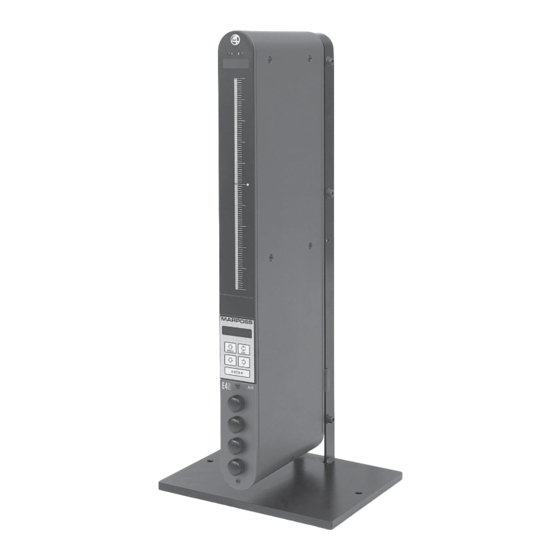
INTRODUCTION DESCRIPTION The E4N column is an electronic gauge amplifier designed for the inspection of part di- mensions and shape in the dynamic and static modes. The E4N column is: CONFIGURABLE The E4N can be configured to manage a wide va- riety of measuring tasks and hardware set ups. -
Page 8: Front And Rear Views
INTRODUCTION FRONT AND REAR VIEWS Hook 2 LED indicators: • Meas. 1 or Meas. 2 programming Plate showing serial number and power supply specification 4-digit display for • LED full scale or resolution Power supply switch • Function messages • Error messages Fuse Three-color scale Power supply connector... -
Page 9: Overall Dimensions
INTRODUCTION eD Display 101 LED scale ar Display 3-color LED (automatic color change) olor 257 mm (from bottom to centre) eight Brightness, response rate rogramming absolute or relative Figure Dot matrix Display millimeters, inches oF measurement static dynamic oF measurement (Max + Min) /2 Max - Min (Max - Min) /2... -
Page 10: Installation And Use
INSTALLATION AND USE MECHANICAL INSTALLATION E4N columns can be mounted singly or in groups of up to 5 units on a stand (for identification codes, see Section 11). : Stand. : Extension pins. CONNECTION OF A COLUMN TO THE MAINS POWER SUPPLY The E4N can be used with a mains power supply in the range 85 to 265 V a.c. -
Page 11: C Onnection To The Mains Power Supply Of A Group Of E4N Columns
INSTALLATION AND USE CONNECTIONS TO THE MAINS POWER SUPPLY OF A GROUPS OF E4N COLUMN E4N columns can be mounted singly or in groups of up to 5 units on a single stand. Groups of E4N columns must be connected to each other in series using the power jumper cables (B). -
Page 12: C Onnecting Trasducers
INSTALLATION AND USE CONNECTION TO THE MAINS COMPRESSED AIR SUPPLY E4N columns fitted with air/electronic modules must be connected to a mains compressed air supply. The air must be filtered and dry and must be at a nominal pressure of 3 bar or between 1.5 and 4 bar;... -
Page 13: Y" Signal Splitter Cable
INSTALLATION AND USE "Y" SIGNAL SPLITTER CABLE A "Y" input signal splitter can be used to carry all the signals used by a group of columns. "Y" cables are only available for splitting signals from LvDT and MRT type sensors. (For identification codes, see Section 11). - Page 14 This test checks that the CPu driving the LED scale is operating correctly and is compatible with the central CPu. At the end of the self-test routine (duration approx. 10 seconds), the column will display the following two messages in succession: E4N V6.2 MARPOSS: PROG PROG E N T E R E N T E R...
-
Page 15: How To Program The E4N Column
HOW TO PROGRAM THE E4N COLUMN This section provides instructions on how to program the E4N column and make use of the column's full potential. one ch. use " " programming for measuring tasks involving the use of one sensor only. two ch. -
Page 16: General Editing Rules
PROG E N T E R +0.0000 NUMERIC DATA MENU PROG E N T E R MEASuRE: MARPOSS STRINGS PROG E N T E R M.SYST= VARIABLE PROG E N T E R USING THE KEYS E N T E R... - Page 17 DOWN arrow keys also allow to RESET the numerical data (i.e. not to program it). STRINGS MARPOSS Select the character to the LEFT of Select the NEXT character the flashing character PROG...
-
Page 18: Entering And Exiting The Programming Mode
HOW TO PROGRAM THE E4N COLUMN ENTERING AND EXITING THE PROGRAMMING MODE This section describes the procedure for entering and exiting the PROGRAMMING mode. TO ENTER: one ch. PROGRAM: P R O G one ch. two ch. PROG PROG PROG E N T E R E N T E R E N T E R... -
Page 19: Selecting The Programming Language
HOW TO PROGRAM THE E4N COLUMN SELECTING THE PROGRAMMING LANGUAGE The E4N is supplied with English set as the default programming language. To change the lan- guage and display menu names, variables and other messages so that they correspond with the terms used in the instruction manual in your hands, proceed as follows: PROGRAM: P R O G... -
Page 20: Default Programming Values
HOW TO PROGRAM THE E4N COLUMN TR.ADJ: MEASURE: PROGRAM: SAVE PROG PROG PROG PROG E N T E R E N T E R E N T E R E N T E R Step 9 Step 10 Step 11 Step 12 SAVE PROG... -
Page 21: "Program:" Menu
HOW TO PROGRAM THE E4N COLUMN "PROGRAM:" MENU 3.6. The main menu "PROGRAM:" contains three programming options: - one ch. (programming for one transducer) - two ch. (programming for two transducers) - all (programming for a maximum of four trasducers) PROGRAM: one ch two ch... -
Page 22: Advanc .:" Menu
(Resolution of the digital display) E N T E R COMM.: PROG (See "COMM:" Menu, Section 3.6.5) IDENTIF= E N T E R MARPOSS (E4N column identificaion) PASS= R___ PROG (Password for programming functions) LUMIN= E N T E R... -
Page 23: "Tr.adj:" Menu
HOW TO PROGRAM THE E4N COLUMN 3.6. "TR.ADJ:" MENU The "TR.ADJ:" menu contains the variables to program the measurement range and the sensitivity of the sensors. TR.ADJ: Default values: (Measurement range assigned to channel A) 250 n.r. W.R.A= PROG SENS.A: (Sensor A sensitivity and/or arm ratio +1.000 correction coefficient) - Page 24 HOW TO PROGRAM THE E4N COLUMN Note: To restore the default values, you must first select and modify the value for any variable and exit from that variable in order to access the SAVE/RESTORE/RESET mode. metric M.SYST= metric inch inch PROG PROG PROG...
-
Page 25: Variables In The "Measure:" Menu
HOW TO PROGRAM THE E4N COLUMN To restore the default values, proceed as follows: PROGRAM: SAVE NO CAL N READY PROG PROG PROG PROG E N T E R E N T E R E N T E R E N T E R Step 15 Step 16 Step 17... -
Page 26: Toler += (Upper Tolerance Limit)
HOW TO PROGRAM THE E4N COLUMN 3.8. N.MEAS= (Number of measurements to be carried out) N.MEAS= PROG PROG PROG E N T E R E N T E R E N T E R Step 1 Step 2 Step 3 Step 1: Press the ENTER key to set the variable. -
Page 27: Apprch+= (Upper Tolerance Approach Limit)
HOW TO PROGRAM THE E4N COLUMN Step 1: Press the ENTER key to set the variable. Step 2: Use the LEFT and RiGHT arrow keys to select the digit to be modified (the selected digit is flashing). use the uP and DOWN arrow keys to increase or decrease the value -0030.0 of the flashing digit. -
Page 28: Scale= (Measurement Scale Display)
HOW TO PROGRAM THE E4N COLUMN Step 3: Press the ENTER key to confirm the numeric data and to pass to programming of the -0025.0 next variable. PROG Note: The maximum and minumum values that can be set are the same as the pro- E N T E R grammed upper and lower tolerance limits (see Sections 3.8.3 and 3.8.4). -
Page 29: Absolut= (Measurement Nominal Value)
HOW TO PROGRAM THE E4N COLUMN Step 1: Press the ENTER key to set the variable. Step 2: Use the LEFT and RiGHT arrow keys to select the digit to be modified (the selected digit is flashing). use the uP and DOWN arrow keys to increase or decrease the value -1.000 of the flashing digit. -
Page 30: Master 1= (Deviation Of Master Gauge 1)
HOW TO PROGRAM THE E4N COLUMN 3.8. MASTER 1= (Deviation of master gauge 1) +0015.0 MASTER 1= -0015.0 +0015.0 PROG PROG PROG PROG E N T E R E N T E R E N T E R E N T E R Step 1 Step 2 Step 3... - Page 31 Flow CHRt PROGRAMMING "one ch." " :" menù measURe PROGRAM: one ch. two ch. all. MEASURE: ADVANC.: M.SYS= TOLER+= TOLER-= APPRCH+= APPRCH-= SCALE= K.CH.A= ABSOLUT= MASTER1= MASTER2= The variable of "MEASURE:" menù are listed in section 3.8.
- Page 33 Flow Flow CHRt CHRt PROGRAMMING "two ch." " :" menù measURe PROGRAM: all. one ch. ADVANC: MEASURE: M.SYST= N.MEAS= TOLER+= MEAS 1: MEAS 2: TOLER+= TOLER+= TOLER-= TOLER-= TOLER-= APPROCH+= APPROCH-= APPROCH+= APPROCH+= SCALE= APPROCH-= APPROCH-= K.CH.A= SCALE= SCALE= K.CH.B= K.CH.B= K.CH.A= ABSOLUT=...
- Page 35 Flow Flow CHRt CHRt PROGRAMMING "all." " :" menù measURe PROGRAM: one ch. two ch. ADVANC: MEASURE: M.SYST= N.MEAS= MEAS 3: MEAS 1: MEAS 2: MEAS 1: MEAS 2: TOLER TOLER-= TOLER TOLER TOLER TOLER TOLER TOLER-= TOLER-= TOLER-= TOLER-= APPRCH+= TOLER-= APPRCH+=...
- Page 37 Flow Flow CHRt CHRt PROGRAMMING "all." " :" menù measURe PROGRAM: one ch. two ch. ADVANC: MEASURE: M.SYST= N.MEAS= MEAS 1: MEAS 4: MEAS 2: MEAS 3: TOLER TOLER TOLER TOLER TOLER-= TOLER-= TOLER-= TOLER-= APPRCH+= APPRCH+= APPRCH+= APPRCH+= APPRCH-= APPRCH-= APPRCH-= APPRCH-=...
-
Page 39: Variables In The "Advanc.:" Menu
HOW TO PROGRAM THE E4N COLUMN VARIABLES IN THE "ADVANC.:" MENU 3.9. LANGUAG= (Language) english francais LANGUAG= english italiano deutsch espanol italiano PROG PROG PROG E N T E R E N T E R E N T E R Step 1 Step 2 Step 3... -
Page 40: Type Type Of Measurement
HOW TO PROGRAM THE E4N COLUMN -1.000 PROG Step 3: Press the ENTER key to confirm the numeric data. E N T E R Note: To program the variable "SENS. B=" "SENS. C=" "SENS. D=" follow the Step 3 same procedure. 3.9. -
Page 41: M.unit= (Unit Of Measurement)
HOW TO PROGRAM THE E4N COLUMN M.UNIT= (Unit of measurement) 3.9. micron M.UNIT= micron micron inch millions thousand PROG PROG PROG E N T E R E N T E R E N T E R Step 1 Step 2 Step 3 Step 1: Press the ENTER key to set the variable. -
Page 42: Thresh.= (Threshold Value For Automatic Switching)
HOW TO PROGRAM THE E4N COLUMN THRESH.= (Threshold value for automatic switching) 3.9. This parameter appears only if the number of programmed measurements is bigger than one. The automatic switch among the measurements is therefore possible only if they are static. AuTOMATIC SWITCH BETWEEN TWO STATIC MEASuREMENTS More measurements can be carried out on the same column if - they are obtained as a linear combination of different transducers... -
Page 43: Commut= (Commutation Mode)
HOW TO PROGRAM THE E4N COLUMN 3.9. COMMUT= (Commutation mode) AUTO COMMUT= AUT/MAN DELTA SW PROG PROG PROG E N T E R E N T E R E N T E R Step 1 Step 2 Step 3 Step 1: Press the ENTER key to set the variable. Step 2: Use the LEFT and RiGHT arrow keys to select the table data required. -
Page 44: Baudr= (Data Transmission Speed In Bit/Sec.)
HOW TO PROGRAM THE E4N COLUMN Step 1: Press the ENTER key to set the variable. printer Step 2: Use the LEFT and RiGHT arrow keys to select the table data required. Step 3: Press the ENTER key to confirm the table data and to pass to programming of the next variable. -
Page 45: Parity= (Parity Bit)
HOW TO PROGRAM THE E4N COLUMN PARITY= (Parity BIT) 3.9. none even PARITY= none even PROG PROG PROG E N T E R E N T E R E N T E R Step 1 Step 2 Step 3 Step 1: Press the ENTER key to set the variable. Step 2: Use the LEFT and RiGHT arrow keys to select the table data required. -
Page 46: Lin_Ter= (Value Line Close)
Step 4: Press the ENTER key to confirm the string and to pass to programming of the next variable. Note: The identification name is MARPOSS by default. To transmit data an identification number has to be programmed within opening and closing characters (see above example). If more than one column is connected to the same PC the identifi-... -
Page 47: Pass= (Programming Password)
HOW TO PROGRAM THE E4N COLUMN 3.9. PASS= (Programming password) R___ 0000 1000 PASS= PROG PROG PROG PROG E N T E R E N T E R E N T E R E N T E R Step 2 Step 1 0123 Step 1: Press the ENTER key to set the variable. -
Page 48: O.r.ck.= (Out-Of-Range Sensor Check)
HOW TO PROGRAM THE E4N COLUMN O.R.CK.= (Out-of-range sensor check) 3.9. O.R.CK.= PROG PROG PROG E N T E R E N T E R E N T E R Step 1 Step 2 Step 3 Step 1: Press the ENTER key to set the variable. Step 2: Use the LEFT and RiGHT arrow keys to select the table data required. - Page 49 Flow CHRt only one measure PROGRAMMING "one ch." " .:" menù aDvanC PROGRAM: one ch: two ch: MEASURE: ADVANC.: LANGUAG= TR.ADJ: W.R.A= M.TYPE= SENS.A= DISPLAY= M.UNITS= M.FILTR= RISOLUT= COMM.: DIGIMAT= IDENT= RS 232= PASS= LUMIN= printer O.R.CK= BAUDR= DATABIT= PARITY= HAND-SH= LINxPAG= The variable of "ADVANC.:"...
- Page 51 Flow CHRt two measure PROGRAMMING "two ch." Programming example with COMMUT= AUTO, MAN, AUT/MAN " .:" aDvanC menù PROGRAM: completo one ch: two ch: MEASURE: ADVANC.: LANGUAG= TR.ADJ: W.R.A= MEAS 1: SENS.A= MEAS 2: W.R.B= DISPLAY= DISPLAY= SENS.B= M.UNIT= M.UNIT= COMMUT= M.FILTR= M.FILTR=...
-
Page 53: Delta Sw Menù Advanc
Flow CHRt three measure PROGRAMMING "all" Programming example with COMMUT= con COMMUT=delta sw " .:" menù aDvanC PROGRAM: one.ch. two.ch. ADVANC: MEASuRE: LANGuAG= TR.ADJ: W.R. A= MEAS.1: SENS. A= MEAS.2: MEAS.3: W.R. D= COMMuT= SENS. D= DISPLAY= DISPLAY= DISPLAY= COMM: DIGIMAT= M.UNIT= M.UNIT=... -
Page 55: E4N Column
(+ or -). See Section 3.8.8. MEASURING AN OUTER DIAMETER WITH ONE SENSOR EQuIPMENT REQuIRED: 1 - E4N COLUMN 1 - MARPOSS M4 MANUAL RING GAUGE 1 - MASTER GAUGE DATA: PART TO BE MEASuRED = PIN OuTER DIAMETER NOMINAL DIMENSION = 50.000 mm ±... - Page 56 PROGRAMMING DATA SHEET FOR E4N COLUMN DATE: E4N COLUMN: SERIAL NUMBER: DEPARTMENT: OPERATOR: MACHINE: PART DESCRIPTION: PART NUMBER: ONE CH. ADVANC: MENu PROGRAM: M.UNIT= micron TWO CH. ENGLISH LANGuAG= NORMAL FRANCAIS M.FILTER= MEASuRE: MENu HIGH DEUTSCH ESPANOL NO FILTER METRIC M.SYST= ITALIANO INCH...
-
Page 57: Measuring An Inner Diameter And An Outer Diameter With Two Sensors
PROGRAMMING EXAMPLES FOR THE E4N COLUMN MEASURING AN INNER DIAMETER AND AN OUTER DIAMETER WITH TWO SENSORS EQuIPMENT REQuIRED: 1 - E4N COLUMN 1 - MARPOSS M4 MANUAL RING GAUGE 1 - MARPOSS M1 PLUG GAUGE DATA: FiRST PART TO BE MEASURED = RiNG RiNG iNNER DiAMETER NOMiNAL DiMENSiON = 40.000 mm ±... - Page 58 PROGRAMMING DATA SHEET FOR E4N COLUMN DATE: 7651012060 E4N COLUMN: SERIAL NUMBER: XXXXXX DEPARTMENT: OPERATOR: MACHINE: PART DESCRIPTION: PART NUMBER: ONE CH. ADVANC: MENu PROGRAM: M.UNIT= micron TWO CH. ENGLISH LANGuAG= NORMAL FRANCAIS M.FILTER= MEASuRE: MENu HIGH DEUTSCH ESPANOL NO FILTER METRIC M.SYST= ITALIANO...
- Page 59 The following example is related to the gap measurement between a pin and its seat. EQuIPMENT REQuIRED: A FOUR-CHANNEL E4N COLUMN A MANUAL RING GAUGE TYPE MARPOSS M4 A MANUAL BORE GAUGE TYPE MARPOSS M1 STAR EBG TWO SIGNAL SPLITTING CABLES DATA: FiRST PART TO BE MEASURED: SEAT NOMiNAL vALUE OF THE iNTERNAL DiAMETER = 4.000 mm +0/+0.010...
- Page 60 PROGRAMMING DATA SHEET FOR E4N COLUMN DATE: E4N COLUMN: SERIAL NUMBER: DEPARTMENT: OPERATOR: MACHINE: PART DESCRIPTION: PART NUMBER: ONE CH. MEAS 3 MENu: M.UNIT= PROGRAM: micron TWO CH. +0001.0 NORMAL TOLER+= M.FILTER= HIGH -0001.0 TOLER-= NO FILTER MEASuRE MENu: R----.- APPRCH+= FINE RESOLUT=...
- Page 61 COMuNIC MENu: DIGIMAT= ON W/O S RS 232= PRINTER 2400 BAUDR= 4800 9600 7 bit DATABIT= 8 bit NONE PARITY= EVEN NONE HAND-SH= HARDWARE X ON/X OFF LINxPAG= LIN_TER= CR + LF MARPOSS iDENTiF= R--- PASS= NORMAL LuMIN= HIGH O.R.CK=...
- Page 62 PROGRAMMING EXAMPLES FOR THE E4N COLUMN TAPER MEASUREMENT WITH FOUR TRANSDUCERS EQuIPMENT REQuIRED: TWO FOUR-CHANNEL E4N COLUMNS ONE MANUAL BENCH GAUGE TYPE MARPOSS QUICK SET FOUR PENCIL PROBES TYPE MARPOSS RED CROWN FOUR SIGNAL SPLITTING CABLES DATA: PART TO BE MEASURED: SHAFT EXTERNAL DIAMETER VALuE = 60.000 mm +/- 0.030...
- Page 63 +0030.0 NO FILTER TOLER+= LINxPAG= -0030.0 TOLER-= TOLER-= FINE RESOLUT= LIN_TER= STANDARD R----.- CR + LF APPRCH+= MAXIMUM R----.- MARPOSS iDENTiF= APPRCH-= R---.- THRESH= ± 100.0 SCALE= R--- PASS= - 1.000 K.CH.B= NORMAL LuMIN= MEAS 2 MENu: HIGH - 1.000 K.CH.D=...
- Page 64 X ON/X OFF -0000.0 TOLER-= static M.TYPE= R----.- APPRCH+= LINxPAG= R----.- APPRCH-= (M+m)/2 LIN_TER= CR + LF (M-m)/2 ± 50.00 SCALE= MARPOSS iDENTiF= - 1.000 K.CH.A= CENTRAL DISPLAY= R--- BOTTOM PASS= + 1.000 K.CH.B= M.UNIT= NORMAL - 1.000 micron LuMIN= K.CH.C=...
- Page 66 ADJUSTMENT PROCEDURE ADJUSTING LVDT, HBT AND MRT SENSORS A D J PROG o.r. CAN A A D J 0 E N T E R Step 1 Step 2 Step 1: Press the uP arrow key (CAL) and the ENTER key together for two seconds. The column will switch to the ADJuSTMENT mode.
-
Page 67: Djusting Ir Lectronic Sensors
ADJUSTMENT PROCEDURE ADJUSTING AIR/ELECTRONIC SENSORS N.B.: Before performing the following procedures parameters K.CH. and SENS. must be programmed as: K.CH. = -1.000 SENS. = +1.000 To adjust air/electronic sensors, start by adjusting the air supply pressure. Adjust using the pressure regulator and gauge. The pressure setting must be in the range 1.5 bar (min.) to 4 bar (max.). The ideal air supply pressure is 3 bar. - Page 68 ADJUSTMENT PROCEDURE Step 2: Take the values of the two master gauges and calculate the difference (or distance) between the two. Example: Max. master = 50.015 mm Min. master = 49.082 mm Max. master - Min. master = 50.015 - 49.082 = 0.033 mm = 33 µ 33/2 = 16.5 µ...
- Page 69 ADJUSTMENT PROCEDURE Step 8: Remove the Max master and insert the Min.master in the measuring position. +20.0 +16.5 PROG PROG E N T E R E N T E R Step 9 Step 9: Turn the zero adjuster and correct the value shown on the alphanumeric display until it reads +16.5 (Upper limit).
- Page 70 ADJUSTMENT PROCEDURE -------- +16.5 PROG PROG E N T E R E N T E R Step 3 Step 3: Insert the Max. master in the measurement position. Turn the sensitivity adjuster until the value shown on the alphanumeric display is close to +16.5 (Upper limit). Step 4: Remove the Max.
-
Page 71: Function Of The Two Adjusters On The Air/Electronic Module
ADJUSTMENT PROCEDURE -20.0 -16.5 PROG PROG E N T E R E N T E R Step 9 Step 9: Turn the zero adjuster and correct the value shown on the alphanumeric display until it reads -16.5 (Lower limit). Step 10: Repeat the steps above until the difference between the readings displayed for the two masters is less than 25% of the difference between the masters. -
Page 72: Calibration Procedure
CALIBRATION PROCEDURE Before the E4N column can be used, the measuring equipment has to be mechanically and electronically calibrated. CALIBRATION OF ONE OR MORE MEASUREMENTS, EACH WITH ONE MASTER -------- CALIBRAT PROG PROG CAL 1 ZERO E N T E R E N T E R Step 1 Step 1: Press the left arrow key ("CAL"... - Page 73 CALIBRATION PROCEDURE +21.0 +20.0 PROG PROG ZERO ZERO E N T E R E N T E R Step 2 Step 3 Step 2: Insert the gauge in its zeroing master. Note: The value to be programmed as MASTER1 (see par 3.8.10) is the deviation of the min. master or of the max.
-
Page 74: Amplifier Modules
AMPLIFIER MODULES The E4N column can be fitted with four types of of signal amplifer module. AMPLIFIER MODULE FOR LVDT SENSORS LVDT SIGNAL CONNECTOR Versions available: OSCILLATOR GROuND (OSCILLATOR) 1-CHANNEL LVDT NOT CONNECTED 2-CHANNEL LVDT GROuND (SIGNAL) 4-CHANNEL LVDT SIGNAL INPuT NOT CONNECTED The connector is a KFR60 for Sv50/6 screw plugs. -
Page 75: Amplifier Module For Air/Electronic Sensors
AMPLIFIER MODULES AMPLIFIER MODULE FOR AIR/ELECTRONIC SENSORS There are two versions of the amplifier module for AIR/ELECTRONIC sen- sors: VERSION WITH METRIC CONNECTOR (1/8 GAS) VERSION WITH IMPERIAL CONNECTOR (1/8 NPT) The letter A on the amplifier panel indicates the air gage connector. This is a connector for quick-release fittings. -
Page 76: Connection To External Devices
CONNECTION TO EXTERNAL DEVICES CONNECTION TO AN EXTERNAL PUSHBUTTON BOX OR A FOOTSWITCH SIGNAL SHIELD SIGNAL GROuND Z_SHiFT (ZEROiNG). HOLD (A) / DIN_ELAB (B) SEND RuN (ZEROING) Note: A. Enabled for static measurements B. Enabled for dynamic measurements 8.1. EXTERNAL PUSHBUTTON BOX The E4N column can be fitted with an ex- ternal pushbutton box with four pushbuttons. -
Page 77: Footswitch
CONNECTION TO EXTERNAL DEVICES PUSHBUTTON FUNCTIONS IN THE DYNAMIC MEASURING MODE: DIN-ELAB When pressed, this pushbutton outputs the current measurement value; when the pushbutton is released the result of dynamic processing will be displayed. When pressed and held down, this pushbutton initialises and enables dynamic processing;... -
Page 78: Connecting External Devices To A Group Of Columns
CONNECTION TO EXTERNAL DEVICES 8.1. CONNECTING EXTERNAL DEVICES TO A GROUP OF COLUMNS Single pushbutton boxes and footswitches can be connected to a group of several E4N columns using the special connector cables provided (for identification codes, see Section 11). -
Page 80: Interfaces
INTERFACES The column has three interfaces: DIGIMATIC INTERFACE RS232 INTERFACE ANALOG INTERFACE DIGIMATIC INTERFACE The "DIGIMATIC" serial interface is used to transfer the measurement value to a statistical analyzer or a concentrator. SIGNAL SHIELD DATA CLOCK REQuEST Note: The RDY and REQUEST signals are active when the logic level is LOW. - Page 81 INTERFACES ANALOG OUTPUT INTERFACE The analog output interface is used to transfer the measurement value to a statistical analyzer or a recorder. The analog signal is transmitted with two full scale ranges: ± 2.4 Volt on pin 3 ± 10 Volt on pin 4 SIGNAL SHIELD ANOuT 2.4...
-
Page 82: P Rint Mode
INTERFACES 9.3. "PRINT" MODE The print mode is used to connect the E4N column over an RS232 interface to a printer or other external devices such as a personal computer and to transmit measurement data to these devices. The "PRINT PROTOCOL" sends a string of 80 printing ASCII characters followed by a carriage return or a carriage return and a line feed command to the external device. - Page 83 INTERFACES EXAMPLE: TRANSMISSION OF MEASUREMENT DATA TO A PC This is an example of a BASIC PROGRAM used to transmit measurement data to a personal compu- ter. The command is transmitted by pressing the ENTER key on the PC keyboard. OPEN "COM1:9600,N,8,1"...
-
Page 84: Rogramming Error Messages And Solutions
PROGRAMMING ERROR MESSAGES AND SOLUTIONS ALPHANUMERIC 7-SEGMENT DI- ERROR TYPE DESCRIPTION MENU ACTION DISPLAY SPLAY Column waiting for Please wait Programming programming to be ***** *** completed Hardware Sensor not connected Connect the sensor. Measurement out of Check that the sensor ________ range is touching the part. - Page 85 PROGRAMMING ERROR MESSAGES AND SOLUTIONS ALPHANUMERIC 7-SEGMENT DI- ERROR TYPE DESCRIPTION MENU ACTION DISPLAY SPLAY SENS.X= not program- TR.ADJ.: Program SENS X= from Programming (ADVANC.:) 0.750 to 1.250 ERR 22 X = channel X = channel Programming W.R. X= TR.ADJ.: Program (ADVANC.:) not programmed...
- Page 86 PROGRAMMING ERROR MESSAGES AND SOLUTIONS ALPHANUMERIC 7-SEGMENT DI- ERROR TYPE DESCRIPTION MENU ACTION DISPLAY SPLAY Programming THRESH.= error ADVANC.: Program THRESH= to a lower value or OFF (not ERR 37 programmed) The measurement re- ADVANC.: Modify RESOLuT= Programming solution is incompatible ERR 38 TR.ADJ.: W.R.X=...
- Page 87 PROGRAMMING ERROR MESSAGES AND SOLUTIONS ALPHANUMERIC 7-SEGMENT DI- ERROR TYPE DESCRIPTION MENU ACTION DISPLAY SPLAY COMM: Programming BAuDR= not program- Program (ADVANC.:) BAuDR= 2400, 4800 or ERR 90 9600 (select the correct DATABIT for the current printer) COMM: DATABIT= not program- Program DATABIT= 7 Programming (ADVANC.:)
- Page 88 Switch the column OFF (The current measure- and then ON again. WARN 102 ment ID is incorrect). If the problem persists, call a Marposs Service Centre. Programming The E2PROM is incom- Press ENTER to reset the patible with the column column;...
- Page 89 PROGRAMMING ERROR MESSAGES AND SOLUTIONS ALPHANUMERIC 7-SEGMENT DI- ERROR TYPE DESCRIPTION MENU ACTION DISPLAY SPLAY Hardware LED scale fault Contact a Marposs Service Center Software ERR 506 Hardware Communications error Contact a Marposs between the CPu and Service Center ERR 507 the LED scale.
-
Page 90: Ccessories And Spare Parts
ACCESSORIES AND SPARE PARTS... -
Page 91: Spare Parts And Power Supply Cables
................6344450100 LOCAL PROGRAMMING MODULE ...................... 6876004013 1 LVDT AMPLIFIER FITTING KIT ......................6876004005 1 INPUT HBT AMPLIFIER, STANDARD MARPOSS................6876004008 1 INPUT MRT AMPLIFIER ........................6876004011 4 LVDT AMPLIFIER FITTING KIT ......................6876004003 4 INPUT HBT AMPLIFIER, STANDARD MARPOSS................ - Page 92 ACCESSORIES AND SPARE PARTS...
-
Page 93: Accessories
CABLE BETWEEN DIGIMATIC OUTPUT AND DATA MYTE 862..............92160 CABLE BETWEEN DIGIMATIC OUTPUT AND DATA MYTE 529-15 ............11.2. PUSHBUTTON BOX AND FOOTSWITCH ref. n° MARPOSS ex. draw. Description code n° 6738099015 FOOTSWITCH FOR DYNAMIC CYCLE (cable L = 2 mt.) .............. -
Page 94: Manuals
ACCESSORIES AND SPARE PARTS 11.2. ACCESSORIES FOR E4N AIR COLUMN ref. n° Description code n° 2915490053 AIR FILTER REGULATOR UNIT FOR COLUMN ..................2915490052 TWO 90° QUICK-RELEASE CONNECTORS ..................2915490050 TWO STRAIGHT QUICK-RELEASE CONNECTORS ................SENSITIVITY ADJUSTER CAP ......................1015420614 1015420615 SENSITIVITY ADJUSTER AND ZERO REGULATOR CAP .............. -
Page 95: A Ppendix - P Rogramming Data Sheet For E4N Column
PROGRAMMING DATA SHEET FOR E4N COLUMN DATE: E4N COLUMN: SERIAL NUMBER: DEPARTMENT: MACHINE: OPERATOR: PART NUMBER: PART DESCRIPTION: ONE CH. K.CH.A= K.CH.A= PROGRAM: TWO CH. K.CH.B= K.CH.B= K.CH.C= K.CH.C= MEASuRE MENu: K.CH.D= K.CH.D= METRIC M.SYST= INCH ABSOLuT= ABSOLuT= N.MEAS= MASTER1= MASTER1= MASTER2= MASTER2=... - Page 96 M.UNIT= COMMuT MENu: micron NORMAL AUTO M.FILTER= COMMuT= HIGH NO FILTER AUT/MAN DELTA SW FINE RESOLUT= STANDARD COMuNIC MENu: MAXIMUM THRESH= DIGIMAT= DELTA= ON W/O S TIME= RS 232= PRINTER MEAS 2 MENu: 2400 BAUDR= 4800 CENTRAL DISPLAY= 9600 BOTTOM 7 bit DATABIT= M.UNIT=...
Need help?
Do you have a question about the TESTAR E4N and is the answer not in the manual?
Questions and answers