
Related Manuals for marposs G25


Summary of Contents for marposs G25
- Page 1 G25 P32 Gear grinding application Installation and user manual Manual Code: D3630000GF...
- Page 2 07.2013 Edition: 11.2016 MARPOSS S.p.A. is not obliged to notify customers of any changes to the product. The descriptions in this manual shall in no way be interpreted as permission for tampering by unauthorised personnel. The warranty covering the equipment shall be void if any evidence of tampering is found.
- Page 3 About the Directive “RoHS” regulating the presence of certain hazardous substances in Marposs electrical and electronic equipment, refer to http://www.marposs.com/compliance_detail.php/eng/rohs About possible use in Marposs products of materials coming from conflict areas, refer to: http://www.marposs.com/compliance_detail.php/eng/conflict_minerals INFORMATION FOR USERS concerning the terms of the National Legislation enforcing the Directive 2012/19/EU on waste electrical and electronic equipment (WEEE).
-
Page 5: Table Of Contents
Introduction ....................7 Testing and Warranty ................. 7 General Safety Regulations ................ 7 Operating Principle ..................8 Technical specifications .................. 9 G25 Probe Technical Specifications ............9 2.1.1 Technical Specifications ..............9 2.1.2 Overall dimensions ................9 P32 Interface Technical Specifications ............. 10 2.2.1... - Page 6 Touch and Probing...
-
Page 7: General Regulations And Instructions
MARPOSS equipment. The descriptions in this manual are intended for the following type of personnel: - MARPOSS or Customer Personnel who are responsible for installation of the equipment. - Customer technical personnel who must operate directly with MARPOSS equipment. -
Page 8: Operating Principle
1.4 Operating Principle The G25 + P32 application is a surface touch and scanning system based on transducer technology. It can be used in two ways: • As a touch probe (Figure 1) for part checking and positioning. • As a rapid surface scanning probe (Figure 2) -
Page 9: Technical Specifications
2. TECHNICAL SPECIFICATIONS 2.1 G25 Probe Technical Specifications 2.1.1 Technical Specifications (Specifications refer to 35 mm stylus) PROBE TYPE PROBE AXES ±X, ±Y, ±Z* Unidirectional repeatability (2σ) 0.4 µm Triggering force in XY plane 0.9 N Triggering force in Z direction 5.5 N... -
Page 10: P32 Interface Technical Specifications
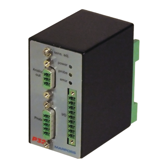
2.2 P32 Interface Technical Specifications The equipment allows TOUCH probes equipped with a transducer to be interfaced with the machine logic and also supplies an analogue output whose voltage is proportional to the movement of the contact which touches the surface scanned. On the front of the equipment are the terminal boards for the I/O (D), analogue output (F), probe input (G), sensitivity adjustment (E) connections and three LEDs for the following indications:... -
Page 11: Technical Specifications
Caution: Before proceeding with connections, follow these instructions: • Make sure that there is no power supplied to the P32 device (green LED A OFF); • Use insulated tools; • If you absolutely have to use metal tools, touch them on a metal surface connected to the earth system to discharge any electrostatic charge built up by the operator. -
Page 12: Overall Dimensions
Note: After any variation in the touch signal the debounce circuit keeps the value fixed for a certain period (which can be set to 50 or 20 ms) to avoid multiple switches. 2.2.2 Overall dimensions Figure 5: P32 interface overall dimensions. Touch and Probing... -
Page 13: Touch And Scanning Speed
(stylus mounted on L-shape adaptor. Contact your local Marposs dealer for more information. • The stylus touch on the surface of the part to be inspected generates a signal used by the machine tool to save the point of contact and to stop the machine axes (part positioning). - Page 14 Touch and Probing...
-
Page 15: Installation
3. INSTALLATION 3.1 Mounting the G25 Probe The G25 probe can be mounted on the machine tool using a support to which it is screwed with the wrench supplied. • The unit is fixed to the machine using two screws (V). -
Page 16: Mounting The Stylus
Styli with smaller diameters Tungsten carbide - Needs crash protection pin Figure 8: Mounting the Stylus. Screw the Stylus (A) into the special thread (B) on the G25 probe. Caution: For correct stylus tightening, use the pair of wrenches supplied. Touch and Probing... -
Page 17: Extensions
3.3 Extensions The extension is an optional accessory for use in deep gauging. • Check that the O-rings (B-D) are in perfect condition. • Screw the probe (A) onto the extension (C) using the wrench supplied with a 10 Nm tightening torque. •... -
Page 18: Electrical Connections
Electrical Connections I/O CONNECTOR Disable INHIBIT input Normally closed PROBE output Remote LED (if present) Power supply voltage Numeric control Figure 10: “Normally closed” configuration I/O CONNECTOR Disable INHIBIT input Normally open PROBE output Remote LED (if present) Power supply voltage Numeric control Figure 11: “Normally open”... -
Page 19: Inhibit Function
CONNECTOR FOR VOLTMETER DEBOUNCE TIME N.O. PROBE OUTPUT N.C. POLARITY Figure 12: Programming points. Caution: Ensure the following conditions have been satisfied before selecting the output polarities or debounce time: • Make sure that the P32 is disconnected from its power supply (Green LED (A) off Figure 4 ). -
Page 20: Analogue Output Connection
3.4.2 Analogue output connection The analogue output of the P32 interface allows connection both of user devices with differential input, and of user devices with unbalanced input. 3.4.2.1 User devices with differential input For maximum immunity against interference it is a good idea to use a differential connection, whose correct set-up is shown in Figure 13. - Page 21 I/O CONNECTOR CONNECTOR FOR ANALOGUE OUTPUT USER DEVICE Figure 13: Connection to user device with differential input. I/O CONNECTOR CONNECTOR FOR ANALOGUE OUTPUT USER DEVICE Figure 14: Connection to user device with unbalanced input. CAUTION! Handle components sensitive to electrostatic discharges very carefully.
-
Page 22: Operating Cycle Charts
3.5 Operating Cycle Charts PROBE OVERCURRENT ON CONNECTION PROBE OUTPUT FAULT (Normally closed) Figure 15: Normally closed. PROBE OVERCURRENT ON CONNECTION PROBE OUTPUT FAULT (Normally open) Figure 16: Normally open. Touch and Probing... -
Page 23: Output Signals
3.6 Output Signals Analogue stroke Jump Gauging Stroke Pre-stroke Figure 17: Output signal in X-Y direction. Stylus length Arm ratio 7.86 10.47 13.07 Typical pre-stroke jump [mm] 0.12 0.17 Typical gauging stroke [V] 0.1-4.1 0.12-0.62 0.1-0.5 0.17-0.82 0.2-1.0 Typical gauging stroke [mm] (range 0.40) (range 0.50) (range 0.65) - Page 24 Analogue stroke Jump Pre-stroke Gauging Stroke Figure 18: Output signal in Z direction. (*) (*) With stylus mounted on L shaped adaptor. Touch and Probing...
-
Page 25: Maintenance
4. MAINTENANCE 4.1 Routine and Extraordinary Maintenance This section covers routine and extraordinary maintenance procedures. • Routine maintenance refers to all operations to be carried out regularly, without requiring specific skills and which, therefore, can be performed by users (operators, etc.). •... -
Page 26: Substituting The Outer Seal
Take the front guard (B) with the seal (C) off the probe body (A). Check the state of the front O-ring (D) and substitute it if necessary. Fit the new front guard with seal until it snaps into place. Figure 19: Example of G25 probe seal substitution. Touch and Probing... -
Page 27: Fault Finding
4.3 Fault finding Indication from LEDs on P32 interface panel. INDICATION CAUSE SUGGESTIONS Green LED OFF No power Check the wiring Yellow LED steady ON No electrical connection Check the integrity of the between probe and cables and the related interface electrical connections. - Page 28 Printed in Italy...
Need help?
Do you have a question about the G25 and is the answer not in the manual?
Questions and answers