
Related Manuals for marposs OP32


Summary of Contents for marposs OP32
- Page 1 OP32 OPTICAL TRANSMISSION TOUCH SYSTEM WITH COMPACT PROBE FOR SMALL MACHINING CENTRES AND MICRO MILLING MACHINES Installation manual Manual code: D31022BG00...
- Page 2 Edition : 07.2016 MARPOSS S.p.A. is not obliged to notify customers of any changes to the product. The descriptions in this manual do not authorise tampering by unauthorised personnel. The guarantee covering the equipment shall be void if any evidence of tampering is found.
- Page 3 Marposs is therefore voluntarily pursuing the progressive removal of the regulated substances from our products. Marposs will do so with the clear understanding that any improvement achieved on the protection of health and the environment should not come as a compromise for the quality and reliability of our products.
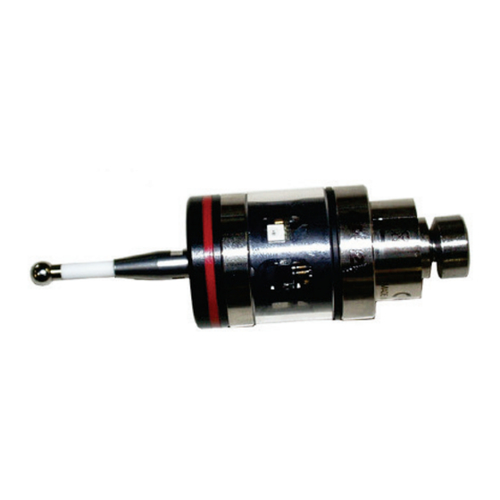
- Page 4 mida...
-
Page 5: Table Of Contents
3.3 ORI Receiver dimensions ............................12 3.4 Interface unit dimensions ............................13 4. INSTALLING THE TRANSMITTER ..........................15 4.1 Inserting/substituting the OP32 transmitter battery ....................15 4.2 Inserting/substituting the OP32E transmitter battery ....................16 4.3 Installing the transmitter/probe on the cone ......................17 4.4 Aligning the system .............................. - Page 6 mida...
-
Page 7: Standards And Warnings
1. STANDARDS AND WARNINGS FOREWORD This instruction manual aims to provide all the specific information necessary to understand and operate your MARPOSS equipment correctly. The descriptions contained in this manual are intended for the following categories of personnel: • The MARPOSS or Customer personnel responsible for installing the equipment. - Page 8 mida...
-
Page 9: System Components
2. SYSTEM COMPONENTS OP32 is a measurement system with optical transmission for high-precision industrial applications. The are two possible system configurations depending by the type of receiver used (E83/ORI 2.1 Configuration with E83 Receiver The system consists of three units: in a one body there are a infrared transmitter powered by battery and a touch probe. -
Page 10: Configuration With Ori Receiver
The integrated interface, based on a process updates the status of outputs to the CNC. This unit is mechanically fixed to the machine C. ORI Receiver with integrated interface A. OP32/OP32E Probe/rtansmitter D. ORI Receiver extension cable B. Finger Figure 2-2. System components – configuration with ORI receiver. -
Page 11: External Dimensions
3. EXTERNAL DIMENSIONS 3.1 Probe/Transmitter dimensions Figure 3-1. OP32 Probe/Transmitter dimensions Figure 3-2. OP3E Probe/Transmitter dimensions OP32 – Installation manual... -
Page 12: E83 Receiver And Adjustable Support Dimensions
3.2 E83 Receiver and adjustable support dimensions 92 (3.62”) 55 (2.16”) 80 (3.15”) (1.02”) ∅ 5,5 (∅ 0.21”) 18,5 (0.73”) ∅ 21 (∅ 0.82”) 116 (4.57”) 50 (1.97”) 70 (2.75”) Figure 3-3. E83 Receiver and adjustable support dimensions. 3.3 ORI Receiver dimensions Figure 3-4. -
Page 13: Interface Unit Dimensions
3.4 Interface unit dimensions (2.78”) 48,5 (1.91”) (3.15”) Figure 3-5. Interface unit dimensions. OP32 – Installation manual... - Page 14 mida...
-
Page 15: Installing The Transmitter
4. INSTALLING THE TRANSMITTER 4.1 Inserting/substituting the OP32 transmitter battery The OP32 transmitter uses two Alkaline SR44 -1.55V batteries. The batteries (A) are housed in the battery compartment (B); to access them: • remove the cover (C) undoing the screws with a screwdriver (D). -
Page 16: Inserting/Substituting The Op32E Transmitter Battery
4.2 Inserting/substituting the OP32E transmitter battery The OP32E transmitter uses one lithium 1/2 AA - 3,6V battery. The battery (A) is housed in the battery compartment (B); to access them: • remove the cover (C) undoing the screws with a screwdriver . •... -
Page 17: Installing The Transmitter/Probe On The Cone
Once the probe has been centred, first tighten the grub screws (A) that secure the probe to the cone to • 0,6 Nm, then the aligning screws (B). Figure 4-3. Mounting the transmitter on the cone. OP32 – Installation manual... -
Page 18: Installing The Finger
4.5 Installing the finger To mount the finger on the probe/transmitter proceed as follows: • Use the open-end spanner (cod. 1320007000), supplied into tools kit, to tighten the stylus. • Insert and screws the finger (A) on the probe/transmitter (B) •... -
Page 19: Connecting The E83 Receiver
(E32R SSR relay probe output) to E83 interface input 3 “AUX”. Select either between the optical and cable systems according to the following table: PROBE SEL ACTIVE PROBE OPEN / 0V OPTICAL PROBE 24 V AUXILIARY PROBE OP32 – Installation manual... -
Page 20: Description Of The Agc (Automatic Gain Control) Anti-Disturbance Function
The function should be activated in the application every time there are significant optical disturbances, which are indicated in the TXs, when they are in stand by mode, by the red LED flashing every 4 seconds (OP32 and E83MC) and in the E83RX receiver with the green "on"... -
Page 21: Changing The Receiver Cable Output Position
• Insert the sheath (D) and screw it to the collet (E). • While holding the cable clamp (A) still, lock the sheath in position using the nut (C). Figure 5-2. Changing the receiver cable output position OP32 – Installation manual... -
Page 22: I/O Diagram
5.4 I/O DIAGRAM SOLID STATE RELAY SIGNALS Open Probe state closed Open Probe state closed open Skip closed open Skip closed open Battery closed open Battery closed open Error closed Figure 5-3. E83 interface I/O diagram. mida... -
Page 23: Connecting The Ori Receiver
It is possible to clean the safety glass with compressed air, by connecting a pneumatic hose to the screw (see Figure 6-2). Connect the pneumatic hose, to the screw with the through hole Compressed air screw Cleaning air exit hole Figure 6-2. Connecting the Compressed Air Hose. OP32 – Installation manual... -
Page 24: Conecting To The Machine Cnc
6.3 CONECTING TO THE MACHINE CNC CONNECTING THE RECEIVER Connector Figure 6-3. ORI receiver & Cable - Connector ELETTRICAL CONNECTIONS Cable sheath Cable size L= 10m – ø = 4.8 mm Inputs Opto-isolated, 15-30V, 0,5 mA max Outputs 3 outputs with SSR 48V, 20mA max WARNING All the conductors that exit the device are isolated from one another, and from the chassis, however, in order to ensure the maximum immunity from electrical noise, whenever possible one of the power supply... - Page 25 CONNECTING TO THE SYSTEM: Figure 6-4. System connection diagram I/O DIAGRAM: Figure 6-5. Inputs/Outputs diagram. OP32 – Installation manual...
-
Page 26: Indicator Led
6.4 Indicator Led The multi-colour LED indicates the system status according to the following table: GREEN YELLOW WHITE BLUE CYAN Figure 6-6. ORI Led. LED colour Probe status Graphic hint GREEN BLUE Flashing three colours Power On Self Test ok ... - Page 27 Cyan LED with flashing red CYAN CYAN (128ms) Battery KO 128ms 128ms Signal level low This indication appears during reception of the probe at rest status when the battery is discharged and the signal level is low OP32 – Installation manual...
-
Page 28: Dip-Switch Programming
6.5 Dip-Switch programming The system is programmed by a series of DIP_SWITCHES accessed by turning the ring D (Figure 6-7): Figure 6-7. Dip-Switch programming. DIP-SWITCH NOME PROBE OUTPUT=SKIP (*pulse to 0 PROBE OUTPUT=NORMAL (probe SKIP ENABLE each time the probe status changes) status;... -
Page 29: Technical Specification
PROBE 1 : (normally open/normally closed contact - N.O./N.C., programmable via the dip-switch H 6 - “Programming the interface unit”). Output signal indicating the state of the probe in use (probe at rest or probe deflected). OP32 – Installation manual... - Page 30 PROBE 2/SKIP: (normally open/normally closed contact - N.O./N.C., programmable via the dip-switch H 7 - “Programming the interface unit”). Additional output signal indicating the state of the probe in use; can be programmed as a probe state signal (at rest or deflected) or SKIP (pulse) signal, depending on the position of the dip-switch H 4 - “Programming the interface unit”.
-
Page 31: Ori Receiver With Integrated Interface
Current consumption 50 mA in reception 100 mA when switching outputs 250 mA average probe activation/deactivation period (max 250 mA) Signal interpretation: Compatible with OP32 and selective activation transmitters (E.g. E83MC, E83WA, E83TXL) Weight: 85 g Protection class: IP68 front... - Page 32 mida...
-
Page 33: Programming The E83 Interface Unit
To program the interface unit proceed as follows (Figure 8-1): the interface unit must be switched off. • undo the fixing screws and remove the panel. • Figure 8-1. Programming the interface unit. OP32 – Installation manual... - Page 34 Use the dip-switch (H) to program the operating mode, in accordance with the table (the factory-set configuration is indicated inside the grey border): DIP-SWITCH Signal reception: normal Signal reception: fast. Ensure maximum immunity from optical interference by other light sources. Transmission stopped by logic signal (input Transmission stopped automatically after fixed period signal lagging edge START).
-
Page 35: Signal Transmission
Data will only be communicated if the receiver (RX) is located within the transmitter (TX) transmission area and the transmitter is located within the receiver reception area simultaneously. OP32/OP32E WITH E83 RECEIVER OP32/OP32E WITH ORI RECEIVER Figure 9-1. Signal transmission. -
Page 36: Activating And Deactivation Of Transmission
9.1 Activating and deactivation of transmission The transmitter is normally in the stand-by condition; transmission is activated optically When the transmitter is not in use it must be deactivated (set to Stand-By) in order to achieve maximum battery life. The activation and deactivation of the transmission can be done by logic signals from the PLC or in automatic mode 9.1.1 By PLC logic Using logic signals from the PLC to activate the system guarantees the maximum battery performance... -
Page 37: Spare Parts List
E83 receiver cable20mt. 6871830003 E83 receiver cable10mt. 6134232000 Adjustable receiver support 4152606101 Protective sheath Specify length in metres 8304851000 E83 ORI Compact RX 6739899107 E83 ORI cable 10mt. 6739899113 E83 ORI cable 25mt. 8304850027 E83 Interface OP32 – Installation manual... - Page 38 mida...
- Page 40 Printed in Italy...
Need help?
Do you have a question about the OP32 and is the answer not in the manual?
Questions and answers