Table of Contents
Advertisement
Quick Links
Advertisement
Table of Contents

Subscribe to Our Youtube Channel
Related Manuals for EXFO FTB-3930


Summary of Contents for EXFO FTB-3930
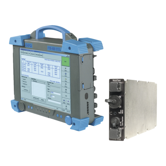
- Page 1 User Guide FTB-3930 Multifunction Loss Tester...
- Page 2 EXFO Inc. (EXFO). Information provided by EXFO is believed to be accurate and reliable. However, no responsibility is assumed by EXFO for its use nor for any infringements of patents or other rights of third parties that may result from its use.
-
Page 3: Table Of Contents
Contents Contents Certification Information ......................v 1 Introducing the FTB-3930 Multifunction Loss Tester ......... 1 Main Features .........................1 Typical Applications ........................3 Conventions ..........................4 2 Safety Information ..................5 Other Safety Symbols on Your Unit ..................6 Laser Safety Information (Units without VFL) ................7 Laser Safety Information (Units with VFL) ................7... - Page 4 Obtaining Online Help ......................80 Contacting the Technical Support Group ................81 Transportation ........................82 14 Warranty ......................83 General Information ......................83 Liability ..........................84 Exclusions ..........................84 Certification ..........................84 Service and Repairs .......................85 EXFO Service Centers Worldwide ..................86 A Technical Specifications ................87 Index .........................89 FTB-3930...
-
Page 5: Certification Information
European Community Declaration of Conformity An electronic version of the declaration of conformity for your product is available on our website at www.exfo.com. Refer to the product’s page on the Web site for details. Multifunction Loss Tester... -
Page 7: Introducing The Ftb-3930 Multifunction Loss Tester
Introducing the FTB-3930 Multifunction Loss Tester The FTB-3930 Multifunction Loss Tester integrates a power meter and light sources with an optical return loss meter, optional talk set and visual fault locator. Main Features The unit features F T™, EXFO’s one-touch automated measurement. - Page 8 The light source has the following characteristics: Singlemode port (two or three wavelengths), also used for F T and ORL. AND/OR Multimode port (two wavelengths), also used for F T only. Modulated or high-power signal compatible with other EXFO units FTB-3930...
-
Page 9: Typical Applications
Introducing the FTB-3930 Multifunction Loss Tester Typical Applications Other test utilities: Text messaging Full-duplex digital talk set (optional) Visual fault locator to inspect or identify fibers (optional) Result processing and analysis features (also available in the FastReporter... -
Page 10: Conventions
Introducing the FTB-3930 Multifunction Loss Tester Conventions Conventions Before using the product described in this guide, you should understand the following conventions: ARNING Indicates a potentially hazardous situation which, if not avoided, could result in death or serious injury. Do not proceed unless you understand and meet the required conditions. -
Page 11: Safety Information
Safety Information ARNING Do not install or terminate fibers while a light source is active. Never look directly into a live fiber and ensure that your eyes are protected at all times. ARNING The use of controls, adjustments and procedures, namely for operation and maintenance, other than those specified herein may result in hazardous radiation exposure or impair the protection provided by this unit. -
Page 12: Other Safety Symbols On Your Unit
One or more of the following symbols may also appear on your unit. Symbol Meaning Direct current Alternating current The unit is equipped with an earth (ground) terminal. The unit is equipped with a protective conductor terminal. The unit is equipped with a frame or chassis terminal. On (Power) Off (Power) FTB-3930... -
Page 13: Laser Safety Information (Units Without Vfl)
The following label(s) indicate that the product contains a Class 3R source: Affixed to Indicated on side of module front panel The maximum input power for the FTB-3930 Multifunction Loss Tester is 1.48 W. For more information on equipment ratings, refer to the user documentation for your platform. Multifunction Loss Tester... -
Page 14: Electrical Safety Information
Safety Information Electrical Safety Information Electrical Safety Information AUTION When you use the unit outdoors, ensure that it is protected from liquids, dust, direct sunlight, precipitation, and full wind pressure. FTB-3930... -
Page 15: Customizing Your Multifunction Loss Tester
Customizing Your Multifunction Loss Tester Note: Your screen display may differ slightly from the figures in this user documentation depending on the platform you are using. To set a length/distance unit and data display color (for the FTB-500): 1. From the main window, press Setup, then select the Preferences tab. 2. - Page 16 Add result to remote unit after F and your Multifunction Loss Tester is the master unit, the result will automatically be sent and stored on the remote unit. Note: For details about naming settings, see Setting Autonaming Scheme on page 14. FTB-3930...
-
Page 17: Setting Up Your Multifunction Loss Tester
Setting Up Your Multifunction Loss Tester Installing the EXFO Universal Interface (EUI) The EUI fixed baseplate is available for connectors with angled (APC) or non-angled (UPC) polishing. A green border around the baseplate indicates that it is for APC-type connectors. -
Page 18: Cleaning And Connecting Optical Fibers
To ensure maximum power and to avoid erroneous readings: Always inspect fiber ends and make sure that they are clean as explained below before inserting them into the port. EXFO is not responsible for damage or errors caused by bad fiber cleaning or handling. - Page 19 EXFO uses good quality connectors in compliance with EIA-455-21A standards. To keep connectors clean and in good condition, EXFO strongly recommends inspecting them with a fiber inspection probe before connecting them. Failure to do so will result in permanent damage to the connectors and degradation in measurements.
-
Page 20: Setting Autonaming Scheme
Fiber names: maximum 11 characters for prefix, plus 3-digit suffix (duplicate names allowed when name is manually set) Note: If you manually change a fiber name, then turn the unit off without saving at least one result, this name will be discarded. FTB-3930... - Page 21 Setting Up Your Multifunction Loss Tester Setting Autonaming Scheme To set the autonaming scheme: 1. From the main window, press Setup, then select the Results tab. 2. Set the names/values, then press OK. Note: The cable name you set here will be the suggested file name when saving. Multifunction Loss Tester...
-
Page 22: Setting Pass/Fail Thresholds
Thresholds are not saved with measurements. Results are compared to the threshold group currently associated to the file (for F results, not necessarily the master unit). Note: When transferring results from handheld unit to computer, thresholds are not transferred along with results. FTB-3930... - Page 23 Setting Up Your Multifunction Loss Tester Setting Pass/Fail Thresholds To set power, loss or ORL thresholds: 1. From the button bar, press Setup, then select the Thresholds tab. Default threshold group Add wavelength and (applies to FasTesT, its thresholds Power Meter and ORL Meter tabs) Edit thresholds for selected wavelength...
- Page 24 6. Press OK to return to the main window. To rename a threshold group: 1. From the Thresholds tab, select a group in the Threshold groups list. 2. Press Rename, then set the new name (maximum 64 characters) and press OK. FTB-3930...
-
Page 25: Measuring Power Or Loss
Measuring Power or Loss The FTB-3930 Multifunction Loss Tester is equipped with an optical power meter to measure absolute power (in dBm or W) or insertion loss (in dB). The power meter port is independent of the F T port. -
Page 26: Defining The List Of Favorite Wavelengths
1470, 1480, 1490, 1570, 1580, 1590, 1600, 1610, 1620, 1510, 1520, 1530, 1540, 1630, 1640, 1650. 1550, 1560,1570, 1625. All the above, plus 1370 and 1060. Same as above. Note: The list must always contain at least one selected wavelength. FTB-3930... - Page 27 Measuring Power or Loss Defining the List of Favorite Wavelengths To customize the list of favorite and selected wavelengths: 1. From the button bar, press Setup, then select the Power Meter tab. 2. Scroll through the list. 3. Press on the highlighted wavelength to select/deselect it. An X appears beside selected wavelengths.
-
Page 28: Nulling Electrical Offsets
3. Tighten the protective caps on the power meter and F T ports, then press OK. The nulling process takes approximately 10 seconds. Nulling status is indicated in the data display. If light is still detected, you will need to place the caps properly and restart. FTB-3930... -
Page 29: Referencing Your Power Meter To A Source
Measuring Power or Loss Referencing Your Power Meter to a Source Referencing Your Power Meter to a Source In reference mode, your unit displays the loss created by the fiber under test only, since it subtracts a reference value from the measured power. Reference power Measured loss... - Page 30 3. Using one of the following methods, connect a light source to the power meter port of your unit. One single reference patchcord Adapter MULTITEST Reference patchcord Light Power source meter FTB-3930 Two reference patchcords and a bulkhead adapter Adapter MULTITEST Reference Reference patchcord patchcord Bulkhead adapter Light...
- Page 31 Measuring Power or Loss Referencing Your Power Meter to a Source 5. Match the power meter wavelength with the source wavelength as follows: Scroll through the Wavelength list to switch between favorite wavelengths of your power meter (see Defining the List of Favorite Wavelengths on page 20).
-
Page 32: Measuring Power Or Loss
5. If you have used a single reference patchcord, disconnect it from the power meter port only, then attach a second reference patchcord to the power meter. If you have used two reference patchcords, disconnect both of them at the bulkhead. FTB-3930... - Page 33 Fiber Adapter under test Light Power source meter FTB-3930 7. Activate the source at the desired wavelength. 8. Match the power meter wavelength with the source wavelength as follows: Scroll through the Wavelength list to switch between favorite wavelengths of your power meter (see Defining the List of Favorite Wavelengths on page 20).
- Page 34 10b.Press Add to save the value along with wavelength, reference power, date and time. The fiber name will increment automatically, ready to save the next value. For details about viewing results, see Managing Test Results on page 49. 11. Repeat the procedure for other wavelengths. FTB-3930...
-
Page 35: Measuring Optical Return Loss
Optical return loss (ORL) is the total effect of multiple reflections and scattering events within a fiber-optic system. The FTB-3930 Multifunction Loss Tester is equipped with an ORL meter to measure ORL for singlemode fibers. The ORL meter uses the F T SM (singlemode) port only. -
Page 36: Performing Orl Reference And Setting Orl Zero Value
DUT, not the reference patchcord) when you remove a connection between the unit and mandrel To set the ORL zero value (all wavelengths at once): 1. From the main window, select the ORL Meter tab. 2. Press ORL Zero. FTB-3930... - Page 37 Measuring Optical Return Loss Performing ORL Reference and Setting ORL Zero Value 3. Connect a patchcord to the F T SM port. Termination Component under test 4. Terminate the fiber as close as possible before the component under test. Wrap it at least 10 turns around a mandrel or small diameter tool, adding turns until the reading stabilizes.
-
Page 38: Performing And Saving Orl Measurements
4. Verify your patchcords and clean them properly (see Cleaning and Connecting Optical Fibers on page 12). Note: If the F T SM port of your unit is equipped with an APC connector, use EXFO’s optional ORL calibrated patchcord. FTB-3930... - Page 39 Measuring Optical Return Loss Performing and Saving ORL Measurements 5. Connect one end of a patchcord to the F T SM port of your unit leaving the other end unconnected. 6. Perform an ORL reference as follows: Note: During the reference, the patchcord end should remain in the air; reflections occurring at a fiber-to-air interface correspond to a constant of 14.7 dB.
- Page 40 9a. Change the displayed cable and fiber names as needed. 9b. Press Add. The fiber name will increment automatically, ready to save the next value. For details about viewing results, see Managing Test Results on page 49. 10. Repeat procedure for other wavelengths if necessary. FTB-3930...
-
Page 41: Performing Automated Il/Orl/Length Measurements (Fastest)
T cuts down on training time and provides error-free results. To use F T, you need a compatible unit (such as FTB-3930, FOT-930, FOT-920 or FTB-3920, but not the FOT-910). The unit at the remote end is only used to establish references. It then waits for commands from the unit initiating F T (master). -
Page 42: Setting Up The Fastest
Compatibility: select FOT-930 / FTB-3930 for fast, two- or three-wavelength testing including ORL (it requires two FOT-930/FTB-3930). Use FOT-920 / FTB-3920 when other unit is an FOT-920 or FTB-3920. Mode/wavelengths: select one or more wavelengths for the F ... - Page 43 Performing Automated IL/ORL/Length Measurements (FasTesT) Setting Up the FasTest To set up the FasTesT: 1. From the button bar, press Setup, then select the F T tab. 2. Select the F T parameters. To revert to factory-default FasTesT settings: 1. From the button bar, press Setup, then select the F T tab.
-
Page 44: Referencing Units For Fastest
ORL use the ORL Meter pane (see calibration accordingly. Performing ORL Reference and Not recommended for short links. Setting ORL Zero Value on page 30). With multiple referencing, you may coordinate an FTB-3930 with up to 10 FOT-930 units. FTB-3930... - Page 45 With its multiple referencing feature, your unit saves the last 10 side-by-side references for each DUT type and compatibility mode. 3. Connect both units through their F T ports, using two reference patchcords and a bulkhead adapter. MULTITEST MULTITEST Reference Reference patchcord patchcord Bulkhead adapter FTB-3930 FTB-3930 Multifunction Loss Tester...
- Page 46 (using bulkhead adapters or the system patch panels). MPORTANT You can turn off the unit without losing the reference. If you disconnect the patchcords from the F T ports, you must take a new reference. FTB-3930...
- Page 47 2. In the Reference pane, select the Loopback reference type. The data display shows previous reference values (if any). 3. Connect a reference patchcord from the F T port to the power meter adapter. MULTITEST Adapter Reference patchcord FTB-3930 Multifunction Loss Tester...
- Page 48 MPORTANT You can turn off the unit without losing the reference. If you disconnect the patchcord from the F T port, you must take a new reference. 6. Repeat the procedure with the second unit. FTB-3930...
-
Page 49: Performing The Fastest
Performing Automated IL/ORL/Length Measurements (FasTesT) Performing the FasTesT Performing the FasTesT Although F T requires two units (one at each end of the fiber under test), you initiate it from only one (the master). Both units use F settings from the master unit. To perform a FasTesT: Unit A (Master) Unit B... - Page 50 Unit A (Master) Unit B 6. Connect reference patchcord to fiber 5. Connect reference patchcord to fiber under test (as shown): under test (as shown): MULTITEST MULTITEST Reference Reference patchcord patchcord Bulkhead Bulkhead adapter adapter Fiber under test FTB-3930 FTB-3930 FTB-3930...
- Page 51 Performing Automated IL/ORL/Length Measurements (FasTesT) Performing the FasTesT Unit A (Master) Unit B 7. From the button bar, press F T (large green button). The units establish communication and automated tests begin. Measurements appear on both units as they are taken. Indicates results not added Indicates to Tested fibers list...
- Page 52 8a. Change the displayed cable and fiber names as needed. 8b. Press Add. The fiber name increments automatically, ready to save the next value. If you are not satisfied with the results, press F T and redo the test. FTB-3930...
- Page 53 Performing Automated IL/ORL/Length Measurements (FasTesT) Performing the FasTesT For details about viewing F T results, see Managing Test Results on page 49. Measured values Calculated fiber length Change name of next added fiber Add current value to Tested fibers (to actually save data, press Save on function bar) Multifunction Loss Tester...
-
Page 55: Managing Test Results
Managing Test Results Viewing and Deleting Results You can save all your results (F T, power/loss and ORL) on your platform, along with references and date/time of tests. You will save and recall this data according to cable names (or any Windows file name). MPORTANT The date and time of F T references are not saved. - Page 56 Shortcut to result sections Result sections To delete results for selected (checked) fibers To mark fiber for deletion Result exceeding threshold Click on link to edit fiber ID or comments FTB-3930...
- Page 57 Managing Test Results Viewing and Deleting Results FTB-200 v2 To mark fiber for To modify job or cable deletion information To select current threshold group MPORTANT The threshold group you select will remain associated with the file, even if you change the default group.
-
Page 58: Customizing Result Display
You can also define default initial cable and fiber names. For details, see Setting Autonaming Scheme on page 14. To customize the display of results: 1. From the main window, press Setup, then select the Results tab. FTB-500 FTB-3930... - Page 59 Managing Test Results Customizing Result Display FTB-200 v2 From Edit Job Information From Edit Cable Information 2. Set parameters and press OK. Multifunction Loss Tester...
-
Page 60: Customizing And Printing Reports (Ftb-500)
Managing Test Results Customizing and Printing Reports (FTB-500) Customizing and Printing Reports (FTB-500) The FTB-3930 Multifunction Loss Tester application allows you to print detailed reports including your custom selection of OLTS data (F ORL and power results with cable and job information). - Page 61 Managing Test Results Customizing and Printing Reports (FTB-500) To print a report: 1. From the main window, press Print. 2. Enter a report title and press Browse to select a logo if desired. 3. Select items to include in the report, as follows: To add or remove an item, check or clear the corresponding box.
-
Page 63: Using A Light Source
Using a Light Source Your unit may contain two source ports: a 2- or 3-wavelength singlemode port and a 2-wavelength multimode port, depending on the configuration. The source signal can be continuous (CW or high-power) or modulated (270 Hz, 1 kHz or 2 kHz) and uses the F T ports. - Page 64 1. Connect the fiber under test to the source port (see Cleaning and Connecting Optical Fibers on page 12). 2. From the main window, select the Source/VFL tab (units with a VFL) or the Source tab (units with no VFL). Data display Power switch Status LED FTB-3930...
- Page 65 Using a Light Source FTB-200 v2 Data display Power button Status LED 3. In the Source pane, select a wavelength using the Wavelength dial (Use the + and - buttons in the case of the FTB-200 v2 platform). 4. Slide the Power switch to On (or press the On/Off button in the case of the FTB-200 v2 platform).
-
Page 67: Identifying Fiber Faults Visually
10 Identifying Fiber Faults Visually The visual fault locator (VFL) helps you identify bends, faulty connectors, splices and other causes of signal loss. From its dedicated port, the VFL emits a red signal which becomes visible at the location of a fault on the fiber. This signal can be continuous (CW, the default) or blinking (1 Hz). - Page 68 5. Without looking directly into the beam, examine the fiber. If light is coming out of the rubber jacket or on the side of the ferrule, the fiber is defective. 6. Deactivate the VFL by sliding the Power switch to Off. FTB-3930...
-
Page 69: Communicating With Other Users
To facilitate communication between opposite ends of a fiber (especially on models with no talk set), you may send text messages to compatible units (such as FOT-930, FTB-3930, FOT-920 or FTB-3920) through their T ports. It is possible to send a predefined message or to write one of your own (maximum 30 characters). - Page 70 Communicating with Other Users Sending and Receiving Text Messages MULTITEST FTB-3930 2. From the main window, select the Talk set/Messages tab (units with a talk set) or the Messages tab (units with no talk set and FTB-200 v2 units). Status display...
- Page 71 Communicating with Other Users Sending and Receiving Text Messages 3. Ensure that the port indicated (SM or MM) is the one you use. Otherwise, do as follows: 3a. In the function bar, press Setup, then select the F T tab. 3b.
-
Page 72: Communicating By Voice
Multifunction Loss Tester application. Once communication is established, it will be maintained even if you use the unit’s other test tools (including F If communication is lost, calling unit will automatically try to reestablish communication. FTB-3930... - Page 73 Communicating with Other Users Communicating by Voice To communicate between units: Calling Unit Receiving Unit 1. Connect the calling unit to one end of 1. Connect the receiving unit to the the fiber via its talk set port, and plug other end of the fiber via its talk set in your headset.
- Page 74 End from the Talk set pane. To adjust the headset volume (calling or receiving unit): From the Talk set pane, move the Headset volume slider to the top (volume increase) or to the bottom (volume decrease). You cannot adjust or mute the ring sound. FTB-3930...
-
Page 75: 12 Maintenance
12 Maintenance To help ensure long, trouble-free operation: Always inspect fiber-optic connectors before using them and clean them if necessary. Keep the unit free of dust. Clean the unit casing and front panel with a cloth slightly dampened ... - Page 76 Maintenance Cleaning EUI Connectors ARNING Looking into the optical connector while the light source is active WILL result in permanent eye damage. EXFO strongly recommends to TURN OFF the unit before proceeding with the cleaning procedure. To clean EUI connectors: 1.
- Page 77 6d. Verify connector surface with a portable fiber-optic microscope (for example, EXFO’s FOMS) or fiber inspection probe (for example, EXFO’s FIP). 7. Put the EUI back onto the instrument (push and turn clockwise).
-
Page 78: Cleaning Detector Ports
4. While applying light pressure (to avoid breaking the detector window), gently rotate the cleaning tip on the detector window. 5. Repeat step 4 with a dry cleaning tip or blow dry with compressed air. 6. Discard the cleaning tips after one use. FTB-3930... -
Page 79: Cleaning Vfl-Type Connectors
EXFO’s FOMS) or fiber inspection probe (for example, EXFO’s FIP). ARNING Only use an EXFO battery. Batteries from other suppliers could result in serious damage to your unit, or personal injuries. Contact EXFO for more information. Multifunction Loss Tester... -
Page 80: Recalibrating The Unit
Under normal use, the recommended interval for your FTB-3930 Multifunction Loss Tester is: one year. For newly delivered units, EXFO has determined that the storage of this product for up to six months between calibration and shipment does not affect its performance (EXFO Policy PL-03). -
Page 81: Recycling And Disposal (Applies To European Union Only)
To ensure that your unit conforms to the published specifications, calibration may be carried out at an EXFO service center or, depending on the product, at one of EXFO’s certified service centers. Calibrations at EXFO are performed using standards traceable to national metrology institutes. -
Page 83: 13 Troubleshooting
13 Troubleshooting Solving Common Problems Problem Possible Cause Solution During offset nulling, you Light reaches at least one Ensure protective caps are get the following message: detector (power meter or tightly screwed on F and power meter ports and “Light detected during perform the nulling again. - Page 84 ORL meter off or exit Probe mode (FOT-930). Remote unit is not Make sure remote unit compatible. isan FOT-930, FTB-3930, FOT-920 or FTB-3920. Selected port on master unit differs from actual Set the port (SM or MM) ...
- Page 85 Probe mode (FOT-930). Remote unit is not Make sure remote unit is compatible. an FOT-930, FTB-3930, FOT-920 or FTB-3920. On Results tab, a box The application is unable to Perform the measurements indicates “Invld” instead of calculate the F T ORL again.
-
Page 86: Obtaining Online Help
Context-sensitive and interactive help is conveniently available at all times to guide you through the use of your application. Note: You will also find a printable PDF version of the FTB-3930 Multifunction Loss Tester user guide on your installation CD. -
Page 87: Contacting The Technical Support Group
Contacting the Technical Support Group To obtain after-sales service or technical support for this product, contact EXFO at one of the following numbers. The Technical Support Group is available to take your calls from Monday to Friday, 8:00 a.m. to 7:00 p.m. -
Page 88: Transportation
Pack the unit in its original packing material when shipping. Avoid high humidity or large temperature fluctuations. Keep the unit out of direct sunlight. Avoid unnecessary shocks and vibrations. FTB-3930... -
Page 89: 14 Warranty
14 Warranty General Information EXFO Inc. (EXFO) warrants this equipment against defects in material and workmanship for a period of three years from the date of original shipment. EXFO also warrants that this equipment will meet applicable specifications under normal use. -
Page 90: Liability
Liability Liability EXFO shall not be liable for damages resulting from the use of the product, nor shall be responsible for any failure in the performance of other items to which the product is connected or the operation of any system of which the product may be a part. -
Page 91: Service And Repairs
5. Return the equipment, prepaid, to the address given to you by support personnel. Be sure to write the RMA number on the shipping slip. EXFO will refuse and return any package that does not bear an RMA number. -
Page 92: Exfo Service Centers Worldwide
Warranty EXFO Service Centers Worldwide EXFO Service Centers Worldwide If your product requires servicing, contact your nearest authorized service center. EXFO Headquarters Service Center 400 Godin Avenue 1 866 683-0155 (USA and Canada) Quebec (Quebec) G1M 2K2 Tel.: 1 418 683-5498... -
Page 93: A Technical Specifications
The following technical specifications can change without notice. The information presented in this section is provided as a reference only. To obtain this product’s most recent technical specifications, visit the EXFO Web site at www.exfo.com. TECHNICAL SPECIFICATIONS External Power Meter... - Page 94 1 in x 10 Weight 0.5 kg (1.1 lb) Temperature Operating 0 °C to 50 °C (32 °F to 122 °F) Storage –40 °C to 70 °C (–40 °F to 158 °F) Relative humidity 0% to 95% non-condensing Warranty (years) FTB-3930...
-
Page 95: Index
Index Index connectors, cleaning........69 connectors, illustration of......1–3 ! ..............16 conventions, safety........4 creating test report........54 customer service.......... 85 customizing test report ....... 54 About button ..........81 after-sales service ........81 analyzing results..........3 applications, typical ........3 dark current effects, eliminating.... - Page 96 ........ 7 laser source. see source length offset nulling ........... 2, 22 fiber........1, 35, 45, 47 online help ..........80 unit............9 optical detector performance ...... 22 light source. see source FTB-3930...
- Page 97 58 features ........... 1 thresholds ..........16 identification label......... 81 shipping to EXFO......... 85 specifications ......... 87 side-by-side referencing method ....38 protective cap ..........72 signal, modulating ....57, 59, 61, 62 singlemode port ........ 1, 35, 57 source activating ..........
- Page 98 3, 63 power meter .......... 19 modifying ..........63 source ............ 58 receiving ..........65 sending..........63 thresholds ..........3, 16 zero measurement, ORL ......30 tools zero-power reference ........22 talk set........... 66 visual fault locator ......... 61 FTB-3930...
- Page 99 CHINESE REGULATION ON RESTRICTION OF HAZARDOUS SUBSTANCES NAMES AND CONTENTS OF THE TOXIC OR HAZARDOUS SUBSTANCES OR ELEMENTS CONTAINED IN THIS EXFO PRODUCT EXFO Indicates that this toxic or hazardous substance contained in all of the homogeneous materials for this part is below the limit requirement in SJ/T11363-2006...
- Page 100 MARKING REQUIREMENTS Product Environmental protection use period (years) Logo This E product EXFO Battery If applicable.
- Page 101 Tel.: 1 978 367-5600 · Fax: 1 978 367-5700 EXFO FINLAND Elektroniikkatie 2 FI-90590 Oulu, FINLAND Tel.: +358 (0) 403 010 300 · Fax: +358 (0) 8 564 5203 TOLL-FREE (USA and Canada) 1 800 663-3936 © 2014 EXFO Inc. All rights reserved. Printed in Canada (2014-04) ...
Need help?
Do you have a question about the FTB-3930 and is the answer not in the manual?
Questions and answers