Table of Contents
Advertisement
Quick Links
Advertisement
Table of Contents

Related Manuals for EXFO FTB-3930


Summary of Contents for EXFO FTB-3930
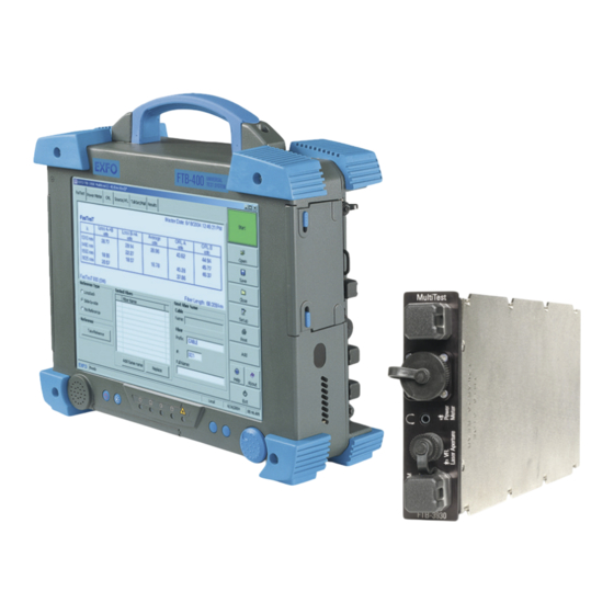
- Page 1 MULTITEST MODULE FTB-3930 NETWORK TESTING USER GUIDE...
- Page 2 EXFO Electro-Optical Engineering Inc. (EXFO). Information provided by EXFO is believed to be accurate and reliable. However, no responsibility is assumed by EXFO for its use nor for any infringements of patents or other rights of third parties that may result from its use.
-
Page 3: Table Of Contents
Contents Contents Certification Information ......................v 1 Introducing the FTB-3930 MultiTest Module ..........1 Main Features .........................1 Typical Applications ........................3 Conventions ..........................4 2 Safety Information ..................5 Laser Safety Information (Units without VFL) ................5 Laser Safety Information (Units with VFL) ................6 3 Getting Started with Your MultiTest Module .......... - Page 4 Recycling and Disposal (Applies to European Union Only) ............80 14 Troubleshooting ..................81 Solving Common Problems ....................81 Obtaining Online Help ......................84 Finding Information on the EXFO Web Site ................84 Contacting the Technical Support Group ................85 Transportation ........................86 15 Warranty ......................87 General Information ......................87 Liability ..........................88...
-
Page 5: Certification Information
F.C.C. Information Electronic test equipment is exempt from Part 15 compliance (FCC) in the United States. However, compliance verification tests are systematically performed on most EXFO equipment. Information Electronic test equipment is subject to the EMC Directive in the European Union. - Page 6 Certification Information DECLARATION OF CONFORMITY Application of Council Directive(s): 73/23/EEC - The Low Voltage Directive 89/336/EEC - The EMC Directive Manufacturer’s Name: EXFO ELECTRO-OPTICAL ENGINEERING INC. Manufacturer’s Address: 400 Godin Avenue Quebec, Quebec Canada G1M 2K2 (418) 683-0211 Equipment Type/Environment: Industrial Scientific Equipment Trade Name/Model No.:...
-
Page 7: Introducing The Ftb-3930 Multitest Module
Introducing the FTB-3930 MultiTest Module The FTB-3930 MultiTest Module integrates a power meter and light sources with an optical return loss meter, optional talk set and visual fault locator. Main Features The unit features F T™, EXFO’s one-touch automated measurement. - Page 8 The light source has the following characteristics: Singlemode port (two or three wavelengths), also used for F T and ORL. AND/OR Multimode port (two wavelengths), also used for F T only. Modulated or high-power signal compatible with other EXFO units FTB-3930...
-
Page 9: Typical Applications
Introducing the FTB-3930 MultiTest Module Typical Applications Other test utilities: Text messaging Full-duplex digital talk set (optional) Visual fault locator to inspect or identify fibers (optional) Result processing and analysis features (also available in the application): Analyze data acquired on the field using a tabular format... -
Page 10: Conventions
Introducing the FTB-3930 MultiTest Module Conventions Conventions Before using the product described in this manual, you should understand the following conventions: ARNING Indicates a potentially hazardous situation which, if not avoided, could result in death or serious injury. Do not proceed unless you understand and meet the required conditions. -
Page 11: Safety Information
Safety Information ARNING Do not install or terminate fibers while a light source is active. Never look directly into a live fiber and ensure that your eyes are protected at all times. ARNING Use of controls, adjustments and procedures for operation and maintenance other than those specified herein may result in hazardous radiation exposure. -
Page 12: Laser Safety Information (Units With Vfl)
If VFL option is available IEC 60825-1:1993+A2:2001 21 CFR 1040.10 LASER RADIATION AVOID DIRECT EYE EXPOSURE CLASS 3R LASER PRODUCT λ: 650 ±10 nm P out maximum < 5mW (into free space) Affixed to Indicated on side of module front panel FTB-3930... -
Page 13: Getting Started With Your Multitest Module
Getting Started with Your MultiTest Module Inserting and Removing Test Modules AUTION Never insert or remove a module while the FTB-400 Universal Test System is turned on. This will result in immediate and irreparable damage to both the module and unit. ARNING When the laser safety LED ( ) is flashing on the FTB-400, at least... - Page 14 (2-slot or 4-slot receptacles) identification sticker must be on left side and retaining screw hole under connector pins. Identification sticker Connector on left side pins at the back Protruding edges on right side FTB-400 right panel (2-slot receptacle) Retaining screw hole at the back FTB-3930...
- Page 15 Getting Started with Your MultiTest Module Inserting and Removing Test Modules (7-slot or 8-slot receptacles) identification sticker must be facing down and connector pins at the left of the retaining screw hole. Connector Retaining pins at the screw hole back at the back Protruding edges on top...
- Page 16 This will secure the module into its “seated” position. Turn retaining screw knob(s) clockwise FTB-400 left panel (2-slot or 4-slot receptacles) FTB-400 left panel (7-slot or 8-slot receptacles) When you turn on the unit, the startup sequence will automatically detect the module. FTB-3930...
- Page 17 Getting Started with Your MultiTest Module Inserting and Removing Test Modules To remove a module from the FTB-400 Universal Test System: 1. Exit ToolBox and turn off your unit. 2. Position the FTB-400 so that the left panel is facing you. 3.
- Page 18 Pulling out a module by a connector could seriously damage both the module and connector. Always pull out a module by its casing. 6. Cover empty slots with the supplied protective covers. AUTION Failure to reinstall protective covers over empty slots will result in ventilation problems. FTB-3930...
-
Page 19: Starting The Multitest Module Application
Getting Started with Your MultiTest Module Starting the MultiTest Module Application Starting the MultiTest Module Application Your FTB-3930 MultiTest Module module may be fully configured and controlled from its dedicated ToolBox application. Note: For details about ToolBox, refer to the FTB-400 Universal Test System user guide. - Page 20 Unit housing the module (1 identifies FTB-400) Slot number in which module is inserted (0 identifies first slot) [ 1 – 1 ] Note: On some 7-slot backplanes, slots are marked with a letter from A to G. FTB-3930...
-
Page 21: Exiting The Application
Getting Started with Your MultiTest Module Exiting the Application Status Bar The status bar, located at the bottom of the main window, identifies the current operational status of the FTB-3930 MultiTest Module. Module status Battery indicator Current date and time Control mode Local: Module controlled locally only. -
Page 23: Customizing Your Multitest Module
Customizing Your MultiTest Module To set a length/distance unit and data display color: 1. From the main window, press Setup, then select the Preferences tab. 2. Select the desired unit and background color. Note: The length unit affects thresholds and fiber length only. MultiTest Module... - Page 24 Add result to remote unit after F and your MultiTest Module is the master unit, the result will automatically be sent and stored on the remote unit. Note: For details about naming settings, see Setting Autonaming Scheme on page 21. FTB-3930...
-
Page 25: Setting Up Your Multitest Module
Setting Up Your MultiTest Module Installing the EXFO Universal Interface (EUI) The EUI fixed baseplate is available for connectors with angled (APC) or non-angled (UPC) polishing. A green border around the baseplate indicates that it is for APC-type connectors, as shown below:... -
Page 26: Cleaning And Connecting Optical Fibers
To ensure maximum power and to avoid erroneous readings: Always clean fiber ends as explained below before inserting them into the port. EXFO is not responsible for damage or errors caused by bad fiber cleaning or handling. Ensure that your patchcord has appropriate connectors. Joining mismatched connectors will damage the ferrules. -
Page 27: Setting Autonaming Scheme
Setting Autonaming Scheme Setting Autonaming Scheme When starting a new file, the unit suggests an initial fiber name. After adding a result to the Tested fibers list, the unit prepares the next fiber name by incrementing the suffix. When you manually change the name for the first time (in Power Meter, ORL Meter or F T), the unit then ignores autonaming settings. - Page 28 To set the autonaming scheme: 1. From the main window, press Setup, then select the Results tab. 2. Set the names/values, then press OK. Note: The cable name you set here will be the suggested file name when saving. FTB-3930...
-
Page 29: Setting Pass/Fail Thresholds
Setting Pass/Fail Thresholds Setting Pass/Fail Thresholds You can define groups of thresholds to specify acceptable power (in W or dBm), power reference (in dB), F T loss (in dB and dB per distance unit) and ORL values (in dB) for each wavelength. Thresholds are supplied by system manufacturers and depend on the system deployed. - Page 30 2. In the Threshold groups list, select a group to modify. Create a new group by pressing New. Duplicate names are allowed, but you should always use distinct names to avoid confusion. 3. Select loss units (dB or dB/distance; distance units are selected in the Preferences tab). FTB-3930...
- Page 31 Setting Pass/Fail Thresholds 4. In the Thresholds list, select a wavelength for which you want to set thresholds, then press Edit. Add a new wavelength to the list by pressing New. Wavelengths that are not supported by F T are simply ignored in F T result tables.
-
Page 33: Measuring Power Or Loss
Measuring Power or Loss The FTB-3930 MultiTest Module is equipped with an optical power meter to measure absolute power (in dBm or W) or insertion loss (in dB). The power meter port is independent of the F T port. Power meter port... -
Page 34: Defining The List Of Favorite Wavelengths
1470, 1480, 1490, 1570, 1580, 1590, 1600, 1610, 1620, 1510, 1520, 1530, 1540, 1630, 1640, 1650. 1550, 1560,1570, 1625. All the above, plus 1370 and 1060. Same as above. Note: The list must always contain at least one selected wavelength. FTB-3930... - Page 35 Measuring Power or Loss Defining the List of Favorite Wavelengths To customize the list of favorite and selected wavelengths: 1. From the button bar, press Setup, then select the Power Meter tab. 2. Scroll through the list. 3. Press on the highlighted wavelength to select/deselect it. An X appears beside selected wavelengths.
-
Page 36: Nulling Electrical Offsets
3. Tighten the protective caps on the power meter and F T ports, then press OK. The nulling process takes approximately 10 seconds. Nulling status is indicated in the data display. If light is still detected, you will need to place the caps properly and restart. FTB-3930... -
Page 37: Referencing Your Power Meter To A Source
Measuring Power or Loss Referencing Your Power Meter to a Source Referencing Your Power Meter to a Source In reference mode, your unit displays the loss created by the fiber under test only, since it subtracts a reference value from the measured power. Reference power Measured loss... - Page 38 3. Using one of the following methods, connect a light source to the power meter port of your unit. One single reference patchcord Adapter MULTITEST Reference patchcord Light Power source meter FTB-3930 Two reference patchcords and a bulkhead adapter Adapter MULTITEST Reference Reference patchcord patchcord Bulkhead adapter Light...
- Page 39 Measuring Power or Loss Referencing Your Power Meter to a Source 5. Match the power meter wavelength with the source wavelength as follows: Scroll through the Wavelength list to switch between favorite wavelengths of your power meter (see Defining the List of Favorite Wavelengths on page 28).
-
Page 40: Measuring Power Or Loss
5. If you have used a single reference patchcord, disconnect it from the power meter port only, then attach a second reference patchcord to the power meter. If you have used two reference patchcords, disconnect both of them at the bulkhead. FTB-3930... - Page 41 Fiber under test Light Power source meter FTB-3930 7. Activate the source at the desired wavelength. 8. Match the power meter wavelength with the source wavelength as follows: Scroll through the Wavelength list to switch between favorite wavelengths of your power meter (see Defining the List of Favorite Wavelengths on page 28).
- Page 42 10b.Press Add to save the value along with wavelength, reference power, date and time. The fiber name will increment automatically, ready to save the next value. For details about viewing results, see Managing Test Results on page 55. 11. Repeat the procedure for other wavelengths. FTB-3930...
-
Page 43: Measuring Optical Return Loss
Optical return loss (ORL) is the total effect of multiple reflections and scattering events within a fiber-optic system. The FTB-3930 MultiTest Module is equipped with an ORL meter to measure ORL for singlemode fibers. The ORL meter uses the F T SM (singlemode) port only. -
Page 44: Performing Orl Reference And Setting Orl Zero Value
DUT, not the reference patchcord) when you remove a connection between the unit and mandrel To set the ORL zero value (all wavelengths at once): 1. From the main window, select the ORL Meter tab. 2. Press ORL Zero. FTB-3930... - Page 45 Measuring Optical Return Loss Performing ORL Reference and Setting ORL Zero Value 3. Connect a patchcord to the F T SM port. Termination Component under test 4. Terminate the fiber as close as possible before the component under test. Wrap it at least 10 turns around a mandrel or small diameter tool, adding turns until the reading stabilizes.
-
Page 46: Performing And Saving Orl Measurements
UPC connector, but do not connect it to the power meter port. During the reference, the patchcord end should remain in the air (reflections occurring at a fiber-to-air interface correspond to a constant of 14.7 dB). FTB-3930... - Page 47 Measuring Optical Return Loss Performing and Saving ORL Measurements 7. Perform an ORL zero measurement (see Performing ORL Reference and Setting ORL Zero Value on page 38). MultiTest Module...
- Page 48 9a. Change the displayed cable and fiber names as needed. 9b. Press Add. The fiber name will increment automatically, ready to save the next value. For details about viewing results, see Managing Test Results on page 55. 10. Repeat procedure for other wavelengths if necessary. FTB-3930...
-
Page 49: Performing Automated Il/Orl/Length Measurements
T cuts down on training time and provides error-free results. To use F T, you need a compatible unit (such as FTB-3930, FOT-930, FOT-920 or FTB-3920, but not the FOT-910). The unit at the remote end is only used to establish references. It then waits for commands from the unit initiating F T (master). -
Page 50: Setting Up The Fas Test
T will not include ORL. Compatibility: select FOT-930 / FTB-3930 for fast, two- or three-wavelength testing including ORL (it requires two FOT-930/FTB-3930). Use FOT-920 / FTB-3920 when other unit is an FOT-920 or FTB-3920. Mode/wavelengths: select one or more wavelengths for the F... - Page 51 Performing Automated IL/ORL/Length Measurements (F Setting Up the F To set up the F 1. From the button bar, press Setup, then select the F T tab. 2. Select the F T parameters. To revert to factory-default F T settings: 1.
-
Page 52: Referencing Units For Fas Tes T
ORL use the ORL Meter pane (see calibration accordingly. Performing ORL Reference and Not recommended for short links. Setting ORL Zero Value on page 38). With multiple referencing, you may coordinate an FTB-3930 with up to 10 FOT-930 units. FTB-3930... - Page 53 With its multiple referencing feature, your unit saves the last 10 side-by-side references for each DUT type and compatibility mode. 3. Connect both units through their F T ports, using two reference patchcords and a bulkhead adapter. MULTITEST MULTITEST Reference Reference patchcord patchcord Bulkhead adapter FTB-3930 FTB-3930 MultiTest Module...
- Page 54 (using bulkhead adapters or the system patch panels). MPORTANT You can turn off the unit without losing the reference. If you disconnect the patchcords from the F T ports, you must take a new reference. FTB-3930...
- Page 55 2. In the Reference pane, select the Loopback reference type. The data display shows previous reference values (if any). 3. Connect a reference patchcord from the F T port to the power meter adapter. MULTITEST Adapter Reference patchcord FTB-3930 MultiTest Module...
- Page 56 MPORTANT You can turn off the unit without losing the reference. If you disconnect the patchcord from the F T port, you must take a new reference. 6. Repeat the procedure with the second unit. FTB-3930...
-
Page 57: Performing The Fas Tes T
Performing Automated IL/ORL/Length Measurements (F Performing the F Performing the F Although F T requires two units (one at each end of the fiber under test), you initiate it from only one (the master). Both units use F settings from the master unit. To perform a F Unit A (Master) Unit B... - Page 58 5. Connect reference patchcord to fiber under test (as shown): under test (as shown): MULTITEST MULTITEST Reference Reference patchcord patchcord Bulkhead Bulkhead adapter adapter Fiber under test FTB-3930 FTB-3930 7. From the button bar, press F (large green button). FTB-3930...
- Page 59 Performing Automated IL/ORL/Length Measurements (F Performing the F Unit A (Master) Unit B The units establish communication and automated tests begin. Measurements appear on both units as they are taken. Indicates unsaved results Indicates results not added to Tested fibers list Standard View Measured values Value under...
- Page 60 8b. Press Add. The fiber name increments automatically, ready to save the next value. If you are not satisfied with the results, press F T and redo the test. For details about viewing F T results, see Managing Test Results on page 55. FTB-3930...
-
Page 61: Managing Test Results
Managing Test Results Viewing and Deleting Results You can save all your results (F T, power/loss and ORL) on your FTB-400 Universal Test System, along with references and date/time of tests. You will save and recall this data according to cable names (or any Windows file name). - Page 62 However, if you change values in the selected group, they will apply to your results. Note: For more accuracy, the loss average is always calculated from loss values in W and then converted to dB. FTB-3930...
-
Page 63: Customizing Result Display
Managing Test Results Customizing Result Display Customizing Result Display You can customize the following elements: Power unit: will affect the Results tab and the printed report, but not the different test tabs. Display F T reference: when selected, the F T references will be shown on the Results tab. -
Page 64: Customizing And Printing Reports
Managing Test Results Customizing and Printing Reports Customizing and Printing Reports The FTB-3930 MultiTest Module application allows you to print detailed reports including your custom selection of OLTS data (F T, ORL and power results with cable and job information). - Page 65 Managing Test Results Customizing and Printing Reports To print a report: 1. From the main window, press Print. 2. Enter a report title and press Browse to select a logo if desired. 3. Select items to include in the report, as follows: To add or remove an item, check or clear the corresponding box.
-
Page 67: 10 Using A Light Source
10 Using a Light Source Your unit may contain two source ports: a 2- or 3-wavelength singlemode port and a 2-wavelength multimode port, depending on the configuration (see Technical Specifications on page 91). The source signal can be continuous (CW or high-power) or modulated (270 Hz, 1 kHz or 2 kHz) and uses the F T ports. - Page 68 3. In the Source pane, select a wavelength using the Wavelength dial. 4. Slide the Power switch to On. To deactivate a light source: Slide the Power switch to Off. To change the signal modulation: 1. Activate the source if you want. 2. Select a modulation using the Modulation dial. FTB-3930...
-
Page 69: Identifying Fiber Faults Visually
11 Identifying Fiber Faults Visually The visual fault locator (VFL) helps you identify bends, faulty connectors, splices and other causes of signal loss. From its dedicated port, the VFL emits a red signal which becomes visible at the location of a fault on the fiber. This signal can be continuous (CW, the default) or blinking (1 Hz). - Page 70 5. Without looking directly into the beam, examine the fiber. If light is coming out of the rubber jacket or on the side of the ferrule, the fiber is defective. 6. Deactivate the VFL by sliding the Power switch to Off. FTB-3930...
-
Page 71: Communicating With Other Users
To facilitate communication between opposite ends of a fiber (especially on models with no talk set), you may send text messages to compatible units (such as FOT-930, FTB-3930, FOT-920 or FTB-3920) through their T ports. It is possible to send a predefined message or to write one of your own (maximum 30 characters). - Page 72 1. Connect the units at each end of the same fiber via their F T ports. MULTITEST FTB-3930 2. From the main window, select the Talk set/Messages tab (units with a talk set) or the Messages tab (units with no talk set).
- Page 73 Communicating with Other Users Sending and Receiving Text Messages 3. Ensure that the port indicated (SM or MM) is the one you use. Otherwise, do as follows: 3a. In the function bar, press Setup, then select the F T tab. 3b.
- Page 74 Press Reply to access the Messages tab and reply to the message. You will then need to return to your previous function manually. However, your last readings will be lost. Note: If the message was written with a language not supported by your unit, you will see unreadable characters only. FTB-3930...
-
Page 75: Communicating By Voice
Communicating with Other Users Communicating by Voice Communicating by Voice With the optional talk set, you can establish full-duplex digital voice communication over a dedicated fiber, even while other functions are in use. The talk set provides adjustable headset volume and uses a dedicated port. It is not compatible with the FOT-920 or FTB-3920 talk sets. - Page 76 2. From the main window, select the Talk set/Messages tab. Status display Headset volume FTB-3930...
- Page 77 Communicating with Other Users Communicating by Voice Receiving Unit Calling Unit 3. Press Talk. Your unit establishes When receiving the call, the unit communication with receiving unit. beeps. A phone icon appears to indicate that communication is established. If no compatible unit is detected at the other end, a message appears.
-
Page 79: 13 Maintenance
13 Maintenance To help ensure long, trouble-free operation: Always clean fiber-optic connectors before using them. Keep the unit free of dust. Clean the unit casing and front panel with a cloth slightly dampened with water. Store unit at room temperature in a clean and dry area. Keep the unit out of direct sunlight. -
Page 80: Cleaning Fixed Connectors
4. With a dry lint-free wiping cloth, gently wipe the same surfaces three times with a rotating movement. 5. Throw out the wiping cloths after one use. 6. Moisten a cleaning tip (2.5 mm tip) provided by EXFO with only one drop of isopropyl alcohol. FTB-3930... - Page 81 9. Continue to turn as you withdraw the cleaning tip. 10. Repeat steps 7 to 9, but this time with a dry cleaning tip (2.5 mm tip provided by EXFO). Note: Make sure you don’t touch the soft end of the cleaning tip and verify the cleanliness of the cotton tip.
-
Page 82: Cleaning Eui Connectors
Pull Push 2. Moisten a 2.5 mm cleaning tip provided by EXFO with one drop of isopropyl alcohol (alcohol may leave traces if used abundantly). 3. Slowly insert the cleaning tip into the EUI adapter until it comes out on the other side (a slow clockwise rotating movement may help). - Page 83 6d. Verify connector surface with a portable fiber-optic microscope (e.g., EXFO’s FOMS) or fiber inspection probe (e.g., EXFO’s FIP). ARNING Verifying the surface of the connector WHILE THE UNIT IS ACTIVE WILL result in permanent eye damage.
-
Page 84: Cleaning Detector Ports
4. While applying light pressure (to avoid breaking the detector window), gently rotate the cleaning tip on the detector window. 5. Repeat step 4 with a dry cleaning tip or blow dry with compressed air. 6. Discard the cleaning tips after one use. FTB-3930... -
Page 85: Recalibrating The Unit
You should determine the adequate calibration interval for your unit according to your accuracy requirements. Under normal use, EXFO recommends calibrating your unit every three years. Note: The FlexCare warranty program includes Calibration/Verification packages (see Service and Repairs on page 89). -
Page 86: Recycling And Disposal (Applies To European Union Only)
This equipment was sold after August 13, 2005 (as identified by the black rectangle). Unless otherwise noted in a separate agreement between EXFO and a customer, distributor or commercial partner, EXFO will cover costs related to the collection, treatment, recovery and disposal of... -
Page 87: 14 Troubleshooting
14 Troubleshooting Solving Common Problems Problem Possible Cause Solution During offset nulling, you Light reaches at least one Ensure protective caps are get the following message: detector (power meter or tightly screwed on F and power meter ports and “Light detected during perform the nulling again. - Page 88 ORL meter off or exit Probe mode (FOT-930). Remote unit is not Make sure remote unit is compatible. an FOT-930, FTB-3930, FOT-920 or FTB-3920. Selected port on master Set the port (SM or MM) unit differs from actual correctly in Setup...
- Page 89 ORL meter off or exit Probe mode (FOT-930). Remote unit is not Make sure remote unit is compatible. an FOT-930, FTB-3930, FOT-920 or FTB-3920. On Results tab, a box The application is unable to Perform the measurements indicates “Invld” instead of...
-
Page 90: Obtaining Online Help
Context-sensitive and interactive help is conveniently available at all times to guide you through the use of your application. Note: You will also find a printable PDF version of the FTB-3930 MultiTest Module user guide on your installation CD. To access online help:... -
Page 91: Contacting The Technical Support Group
Contacting the Technical Support Group To obtain after-sales service or technical support for this product, contact EXFO at one of the following numbers. The Technical Support Group is available to take your calls from Monday to Friday, 7:30 a.m. to 8:00 p.m. -
Page 92: Transportation
Pack the unit in its original packing material when shipping. Avoid high humidity or large temperature fluctuations. Keep the unit out of direct sunlight. Avoid unnecessary shock and vibration. FTB-3930... -
Page 93: 15 Warranty
EXFO Electro-Optical Engineering Inc. (EXFO) warrants this equipment against defects in material and workmanship for a period of three years from the date of original shipment. EXFO also warrants that this equipment will meet applicable specifications under normal use. During the warranty period, EXFO will, at its discretion, repair, replace, or issue credit for any defective product should the equipment need to be repaired. -
Page 94: Liability
Liability Liability EXFO shall not be liable for damages resulting from the use of the product, nor shall be responsible for any failure in the performance of other items to which the product is connected or the operation of any system of which the product may be a part. -
Page 95: Service And Repairs
5. Return the equipment, prepaid, to the address given to you by support personnel. Be sure to write the RMA number on the shipping slip. EXFO will refuse and return any package that does not bear an RMA number. -
Page 96: Exfo Service Centers Worldwide
Warranty EXFO Service Centers Worldwide EXFO Service Centers Worldwide If your product requires servicing, contact your nearest authorized service center. EXFO Headquarters Service Center 400 Godin Avenue 1 866 683-0155 (USA and Canada) Quebec (Quebec) G1M 2K2 Tel.: 1 418 683-5498... -
Page 97: A Technical Specifications
The following technical specifications can change without notice. The information presented in this section is provided as a reference only. To obtain this product’s most recent technical specifications, visit the EXFO Web site at www.exfo.com. SPECIFICATIONS External Power Meter FTB-3932... -
Page 99: Index
1–3 analyzing results..........3 contact information, EXFO ......86 application conventions, safety........4 contacting EXFO support from ....86 creating test report........58 exiting ........... 15 customer service........86, 89 starting, single-module......13 customizing test report ....... 58 applications, typical ........ - Page 100 85 exclamation mark........23 identification, slot ........14 EXFO service centers........90 inserting a module ........7 EXFO support e-mail ........86 insertion loss (IL). see loss EXFO universal interface. see EUI intermittent signal........64 EXFO Web site........84, 86 exiting application........
- Page 101 Index measurement units ........17 measuring pass/fail thresholds. see thresholds loss ............34 PDF. see online help ORL............37 performing power ............ 34 null measurement ........30 message feature. see text messages ORL measurement........40 modulation ORL zero measurement ......38 detection of ........
- Page 102 62 light source ..........61 thresholds..........23 ORL meter ..........37 shipping to EXFO ........89 power meter .......... 27 side-by-side referencing method ....46 text messages signal, modulating ....61, 62, 63, 64 compatibility.......... 65 singlemode port........
- Page 103 Index tools talk set........... 69 zero measurement, ORL....... 38 visual fault locator ......... 63 zero-power reference ........30 see also test tools transferring data ........... 3 transportation requirements ....73, 86 typical applications ........3 unit recalibration......... 79 units of measurement ......... 17 user guide.
- Page 104 EXFO ASIA-PACIFIC 151 Chin Swee Road SINGAPORE 169876 #03-29, Manhattan House Tel.: +65 6333 8241 · Fax: +65 6333 8242 TOLL-FREE (USA and Canada) 1 800 663-3936 © 2006 EXFO Electro-Optical Engineering Inc. All rights reserved. Printed in Canada (2006-07)
Need help?
Do you have a question about the FTB-3930 and is the answer not in the manual?
Questions and answers