
Subscribe to Our Youtube Channel
Related Manuals for RTA TECHNI MOBILI RTA-913D


Summary of Contents for RTA TECHNI MOBILI RTA-913D
- Page 1 HOME OFFICE WORKSTATION WITH STORAGE MODEL RTA-913D ASSEMBLY INSTRUCTIONS REV.NTL-6-7438-0823 Thank you for purchasing our product VIDEO Scan QR to view full assembly video...
-
Page 2: Main Parts List
& Replacement Parts within the Customers & AK-HI-PR orders: of all the parts and 48 Contiguous United States: RTA Products will replace the part free of hardware listed below. charge, while the customer is responsible for shipping costs plus any International Please email us at: support@rtaproducts.com... -
Page 3: Hardware List
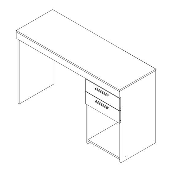
RTA-913D MAIN PARTS LAYOUT (For reference) (x2) ( B a f t ) ( L e c k ) ( F r f t ) h t ) ( L e o n t ( R i g h t ) - Page 4 RTA-913D BEFORE YOU START THE ASSEMBLY, PLEASE READ THE FOLLOWING TIPS AND WARNINGS. • The product assembles ONLY as shown in the front page, with the drawers on the RIGHT side. The drawers cannot install on the LEFT side. • Do not discard this manual or any of the packaging material until the unit is completely assembled.
- Page 5 RTA-913D THE ASSEMBLY STEPS START ON NEXT PAGE CAM BOLT AND CAM LOCK TUTORIAL THE INSTRUCTIONS BELOW ARE NOT ACTUAL ASSEMBLY STEPS This unit uses cam bolts and locks (also known as mini fixes). If you are not familiar with this kind of hardware, the below is a tutorial that explains how to use them on the steps where they are required.
-
Page 6: Assembly Steps
RTA-913D ASSEMBLY STEPS WE RECOMMEND TO PLACE THE PIECES OVER BLANKETS TO PROTECT THEIR FINISH DURING ASSEMBLY. STEP 1 Attach the dowels A into the indicated holes on the panels 2, 3, 4, 5, 6, 7, 9, 10 Hardware and 11. - Page 7 RTA-913D STEP 2 • Attach the bolts B into the indicated holes on panels 1, 2, 6 and 8. Hardware Bolt Tools (NOT included) ( B o t t o ( B o t t o ( B o t t o...
- Page 8 RTA-913D STEP 3 • Grab both sets of sliders O (total 8 pieces) and separate them into 2 groups Hardware according to their shape: • The "flat" ones are the ones used on this step. M6x10 • The "L" shaped won't be used until step 9, so set them aside.
- Page 9 RTA-913D STEP 4 THE CAM LOCKS C ARE INSERTED AFTER PANEL 3 IS INSTALLED. This step requires of 2 persons • With the help of another person, join the left side panel 2 and the middle panel Hardware 4 to the tabletop 1 and keep holding them upright.
- Page 10 RTA-913D STEP 5 THE CAM LOCKS C ARE INSERTED AFTER PANEL 5 IS INSTALLED. This step requires of 2 persons • With the help of another person, join the right side panel 6 to the tabletop 1 Hardware and keep holding it upright.
- Page 11 RTA-913D P.10 P.10 STEP 6 IMPORTANT: Hardware ■ Please note that the neither the tabletop 1 nor the top front panel 7 have M4x12 predrilled holes or any other markings for the brackets N; that is the way they come.
- Page 12 RTA-913D P.11 P.11 STEP 7 • With the help of another person, carefully turn the unit over its front. This step requires of 2 persons Hardware least Nail Tools (NOT included) • Place the back board 13 covering the back of the drawers' cabinet (panels 1, 4, 5 and 6), and secure it with nails J.
- Page 13 RTA-913D P.12 P.12 STEP 8 For each of the drawers: Hardware • Assemble the back panel 11 to the side panels 9 and 10 with screws E. Cam lock M3.5x40 M3.5x25 Sticker Handle Tools (NOT included) • Assemble the front panel 8 to the side panels 9 and 10 with cam locks C as explained in the Cam Lock-Bolt Tutorial page.
- Page 14 RTA-913D P.13 P.13 STEP 9 For each of the drawers: Hardware Flip them upside-down and place on it the drawer bottom board 12, inserting M3x12 one end into the groove of the front panel 8, and use one nail J to secure the least board to the back panel 11 as shown.
- Page 15 RTA-913D P.14 P.14 STEP 10 Insert the drawers into the unit, starting with the bottom one, and with the front Hardware facing down at an angle. If the drawers don't seem to fit, review the assembly done in steps 4 and 12.
-
Page 16: Weight Limits
RTA-913D P.15 P.15 WEIGHT LIMITS 44 Lbs (20 Kg) 6.6 Lbs (3 Kg) 15.5 Lbs (7 Kg) WARNINGS • Do not exceed the indicated weight limits. • Do not expose the surfaces to direct sunlight or to extreme environmental conditions. - Page 17 RTA Products LLC will replace any defective part, at its discretion, and without charge to the original purchaser other than the freight from the end consumer to RTA Products.
Need help?
Do you have a question about the TECHNI MOBILI RTA-913D and is the answer not in the manual?
Questions and answers