
Subscribe to Our Youtube Channel
Related Manuals for Pepperl+Fuchs DoorScan


Summary of Contents for Pepperl+Fuchs DoorScan
- Page 1 DoorScan Active infrared sensor for person detection on automatic doors with a width of up to 1600 mm Original Operating Instructions www.pepperl-fuchs.com www.pepperl-fuchs.com...
- Page 2 If ignored, the consequenc- es range from light to moderate personal injury. Intended Use The DoorScan is used as a protection mechanism the vicinity of moving swing doors and revolving for closing edges on automatic door systems and doors.
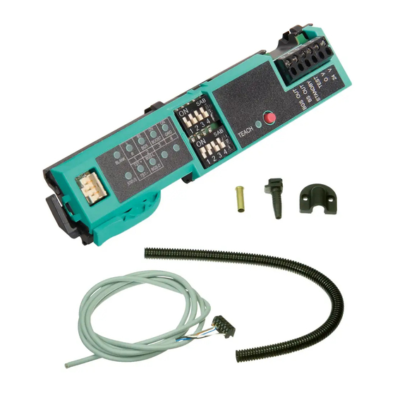
- Page 3 DoorScan Included in Delivery Designation Units Sensing strip End caps with screws Receiver module; blue, always positioned on the right Emitter module; red, always positioned on the left Interface module Double-ended cordset for module ribbon cable Flange connector for corrugated hose...
-
Page 4: Table Of Contents
DoorScan Technical Data Table of Contents Technical Data ............................4 Accessories ............................5 Device Versions ............................5 Display and Control Elements .......................6 Application Notes ..........................7 Mounting ...............................9 Commissioning (Teach-in and Blanking) .....................14 Adjusting the sensor ...........................15 Close the Sensor ..........................18 Fault Indications ..........................19 Declaration of Conformity ........................21... -
Page 5: Accessories
DoorScan-R Receiver module DoorScan-T Emitter module Connection DoorScan Connection Cable 5p Double-ended cordset for module ribbon cable with five plug-in connections DoorScan Transfer Loop Door transition cable to door controller DoorScan Cable BS/BGS Double-ended cordset for transition from door hinge side to hinge... -
Page 6: Display And Control Elements
DoorScan Display and Control Elements Display and Control Elements Interface Blank LED (green) Status Illuminated Blanking active Not illuminated Blanking not active or only partially active DIP LED (green) Status Illuminated * DIP position ON * LEDs switch off after some time... -
Page 7: Application Notes
If it is not possible to feed a cable through the door, install an interface on both sides of the door. This requires an additional interface and another DoorScan Transfer Loop (see Accessories). Small Door Frames with Normal and Rack-and-Pinion Door Closers... - Page 8 DoorScan Application Notes • The sensing strip goes behind the handle • The handle is less than 300 mm away from the leading edge nformation For standard protection according to DIN 18650/EN 16005, for each side of the door you need one emitter module, one receiver module, and one double-ended cordset module (ribbon cable) -->...
-
Page 9: Mounting
DoorScan Mounting Mounting Mounting the Sensing Strips nformation Mount the sensing strips on both sides of the door. max 3,5 mm... - Page 10 Install the sensor modules only on the corrugated sides. Do not exert any pressure on black plastic bodies or lenses as this may cause damage. 500..1000mm DoorScan with a width of 1200 mm On both sides of the door, always position the emitter (RED) on the left and the receiver (BLUE) on the right in the sensing strip.
- Page 11 DoorScan Mounting nformation If you have set up the emitter and receiver module correctly, then it will be possible to move the module easily and close the lever without excess force..
- Page 12 DoorScan Mounting 24 V > brown (BN) > blue (BU) TEST > grey (GY) STANDBY > pink (PK) BS OUT > black (BK) BGS OUT > white (WH)
- Page 13 DoorScan Mounting Connection for Door Controller nformation Choose the appropriate end cap depending on the cable outlet.
-
Page 14: Commissioning (Teach-In And Blanking)
DoorScan Commissioning (Teach-in and Blanking) Commissioning (Teach-in and Blanking) During Teach-in, the sensor first learns the floor surface and then, during a subsequent door opening and closing procedure, the detection area. If the sensor detects walls in the detection area during the door opening and closing procedure, these are also taught into the sensor and suppressed (blanking), in order to enable full door opening during subsequent operation. -
Page 15: Adjusting The Sensor
Attach the end caps but do not tighten them yet. DoorScan Detection Area The sensor uses the active-infrared principle and forms a continuous de- tection field that is almost rectangular on each side of the door. If a person or object interrupts one or more of the light beams, the sensor's switching function is triggered. - Page 16 DoorScan Adjusting the sensor Set DIP switch rows 1 and 2 Row 1 DIP 1 (L/R) Hinge edge right* or left to interface * Factory default setting DIP 2 (BS/BGS) Interface on the door hinge side or hinge opposite side*...
- Page 17 DoorScan Adjusting the sensor Row 2 DIP 1 (TST+/TST-) DIP 1 off: test signal polarity, test at 0 V* DIP 1 on: test signal polarity, test at 24 V * Factory default setting DIP 2 ( DIP 2 off: test triggered by applying the potential corresponding to DIP 1* DIP 2 on: test triggered by interrupting the test connection.*...
-
Page 18: Close The Sensor
DoorScan Close the Sensor Close the Sensor nformation Before closing the sensor, check that the detection area is effective. -
Page 19: Fault Indications
DoorScan Fault Indications Fault Indications Fault after floor Teach-in Check the contact with the ribbon cable on all modules. Yellow Teach LED on the Red status LED on the Receiver LED Receiver is not Replace the receiver module interface is flashing... - Page 20 DoorScan Fault Indications Wall is detected despite Teach-in run Assignment of the interface to the hinge edge is set Yellow Teach LED on the Change the settings of DIP switch 1 up incorrectly interface is off Red status LED on the...
-
Page 21: Declaration Of Conformity
Director Innovation Unit Opto Declaration of conformity / Konformitätserklärung Manager Development Opto KOS We, Pepperl+Fuchs SE declare under our sole responsibility that the ANNEX 2006/42/EC (MD) products listed below are in conformity with the listed European Direc- tives and standards. - Page 22 Pepperl+Fuchs Quality Download our latest policy here: www.pepperl-fuchs.com/quality www.pepperl-fuchs.com Subject to modifications · © Pepperl+Fuchs Printed in Germany · Part. No. 268299/DOCT-3681B...
Need help?
Do you have a question about the DoorScan and is the answer not in the manual?
Questions and answers