Table of Contents
Advertisement
Quick Links
Advertisement
Table of Contents

Related Manuals for Pfeiffer Vacuum adixen ASI 30


Summary of Contents for Pfeiffer Vacuum adixen ASI 30
- Page 1 ASI 30 Modular leak detector Operating Instructions...
- Page 2 Table of contents Table of contents About this manual ..........5 1.1 Validity.
-
Page 3: Table Of Contents
Table of contents 6.1.8 "Measurement" window....... . . 37 6.1.9 Function keys . - Page 4 Table of contents 11.3 Units of measurement........76 11.4 Dimensions .
- Page 5 About this manual Validity This operating manual is for customers of Pfeiffer Vacuum. It describes the functioning of the designated product and provides the most important information for safe use of the unit. The description follows applicable EU guidelines. All information provided in this operating manual refers to the current state of the product's development.
- Page 6 About this manual Conventions 1.2.1 Safety instructions Operating manual safety instructions Pfeiffer Vacuum are based on the UL, CSA, ANSI Z-535, SEMI S2, ISO 3864 and DIN 4844 certification standards. This document de- scribes the following information and danger levels: DANGER Imminent danger Indicates an imminent hazardous situation that will result in death or serious injury.
- Page 7 About this manual 1.2.2 Pictographs Prohibition of an action or activity in connection with a source of danger, the disregarding of which may result in serious accidents Warning of a displayed source of danger in connection with operation of the unit or equipment Command to perform an action or task associated with a source of dan- ger, the disregarding of which may result in serious accidents 1.2.3...
- Page 8 About this manual For service centers use only. Pu_GL : 1 Pu_N : 1 Mu_GL : 12856 Mu_N : 31 Mu_Cal : 1 Mu_LDS : 1800 Indicates the firmware versions installed on the DD-MM-YY product. Factory Firmware /Logiciel usine 1) Firmware name L0232 V3302 E17D...
- Page 9 Safety Safety Safety precautions Obligation to inform Any person responsible for installing, using or maintaining the product must first read the security instructions in this operating manual and comply with them. It is the operating customer’s responsibility to protect all operators against the dan- gers associated with the product, with the media pumped and with the entire instal- lation.
- Page 10 Safety Only qualified personnel trained in safety rules (EMC, electrical safety, chemical pol- lution) may carry out the installation and maintenance described in this manual. Our service centers can provide the necessary training. Do not remove the blanked-off flange from the inlet port while the product is not in use. Do not expose any part of the human body to the vacuum.
- Page 11 Safety pumping of liquids pumping of condensing vapors pumping dust or solid particles operation in potentially explosive areas analysis of gas with a hydrogen concentration higher than 5 % testing parts that are soiled or that have traces of water, vapours, paint, adhesive, de- tergent or rinsing products use of accessories or spare parts, which are not named in this manual The product is not designed to carry people or loads and is not for use as a seat, step-...
- Page 12 Transport and storage Transport and storage Upon delivery, check that the product has not been damaged during transport. If the product is damaged, contact the carrier and notify the manufacturer. In all situations we recommend: Keeping the product in its original packaging so it stays as clean as it was when dis- patched by us.
- Page 13 Product description Product description Product identification To correctly identify the product when communicating with Pfeiffer Vacuum, always have the information from the rating plate available. Fig. 1: Nameplate example 1 Part number 2 Description 3 Weight 4 Operating voltage 5 Operating frequency...
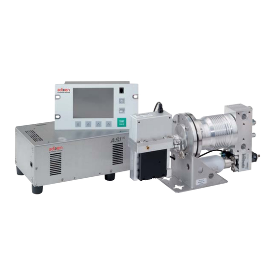
- Page 14 Product description Product overview The product comprises: – a ½ rack 19" 3U-compatible electronic module (1) – a detection module (2) – an industrial control panel compatible ½ rack 19" 3U (option or accessory) (3) 4.2.1 Detection module 1 + 2 Pre-amplifier DN 16 ISO-KF detector inlet port (Gross leak mode)
- Page 15 Product description 4.2.2 Electronic module (see 4.3) Ind. (B). The detection module and the electronic module are connected by 2 cables of the re- quired length - 3.5 m/5 m/10 m or 20 m. The electronic module and the control panel (option/accessory) are connected by one cable of the required length - 1.8 m/5 m or 10 m.
- Page 16 Product description Interface connection START STAND-BY 12/13 12/13 Fig. 2: Human-machine interface Mains power supply (MAIN POWER) SD card Detector inlet (Inlet port) Switch/Circuit breaker (MAIN POWER) Detector ON indicator LED Ethernet plug or Wi-Fi Antenna (NET- WORK) Accessory connector (ACCESSORIES) 11 Accessory (2) (3) Identification of the I/O options provided...
- Page 17 Product description Test methods The test method is chosen depending on the part to be tested. For more information about leak detection test methods, see Leak detector compendium on the website www.pfeiffer-vacuum.com. 4.4.1 Hard vacuum test Part that can be connected to pipe and placed under a vacuum. Part that can be placed in a vacuum chamber.
- Page 18 Installation Installation Prerequisites for optimising measurement To optimise pumping and measurement speed: Use pipe with a diameter equal to the diameter of the detector's inlet. The pipes should be as short as possible and completely sealed. Do not use plastic hoses such as compressed air pipes. Check that the connected part/installation is impermeable to tracer gas.
- Page 19 Installation Fig. 3: Detection module ventilation direction if temperature is over 40°C For an easier module assembly and integration, the calibrated leak or the analyzer cell Positions could be positioned in various positions: the fixing square is reversible. Fig. 4: Possible positions 1-2 Vertical Inclined 0 to 360°...
- Page 20 Installation Effective integration volume: depends on how the 2 sub-assemblies are positioned. Many configurations are therefore possible. Fig. 5: Minimum integration volume for the most compact configuration This is the vacuum module delivered configuration. It is necessary to separate the vacuum module from the secondary pump when carrying out maintenance on the pump: allow sufficient space for dismantling.
- Page 21 Installation 14,5 30,5 14.5 4X4 Ø9 4xØ20 14,5 30.5 Fig. 6: Bracket viewed from underneath (mm) 5.3.2 Electronic module To make integration easier, the electronic module can be placed in any position. The electronic module drawings are available on the operating manual CD-ROM. It is recommended to place and mount the electronic module so that the access to the internal electronic boards can be possible without dismantling the full mo- dule.
- Page 22 Installation A plate for mounting the electronic module in a ½ rack space is supplied with the de- tector (the plate drawing is available on the operating instructions CD-ROM). Fig. 7: Electronic module with ½ rack plate Precautions to take when you fix the control panel and electronic module in a 1 rack for- mat: A GOOD: Electronic module and industrial control panel must be fixed separately on the customer’s installation...
- Page 23 Installation 4 rubber feet are screwed on the electronic module. They allow module positioning on a Feet table. It is possible to screw these 4 feet on the other module sides. Fig. 8: Feet mounting points The electronic module is equipped with a fan and a removable filter system. Ventilation For installation of the unit in "clean"...
- Page 24 Installation 2 fixing clamps for the supply cable are delivered to secure fixing of the supply cable to Power cable fixing electronic module. clamps 2 models, with washer and fixation screw, are delivered to be suited to all power cables. 5.3.3 Industrial control panel Industrial control panel with ½...
- Page 25 Installation – – Fig. 10: Buzzer connection 1 Wiring harness (delivered with the control panel) 2 Buzzer (at the customer's expense) To stop buzzer without disconnecting it, select “Mute” function through a function key (see 7.7.2). Connecting the part/installation to be tested NOTICE Limit of operation Make sure that the parts or chambers connected to the inlet of our products withstand...
- Page 26 Installation ASI 30 Fig. 11: ASI 30 vacuum circuit Pre-amplifier Dust Filter Analyzer cell 2 x DN 16 ISO-KF detector inlet ports (Gross Leak Mode) Internal calibrated leak 2 x DN 16 ISO-KF detector inlet ports (Normal Mode) MDP 5011 IE detection molecular pump Calibration valve 5.4.2 Gross Leak Mode port connection...
- Page 27 Installation Autocalibration of internal calibrated leak: – For the duration of the autocalibration phase, the test valve V will be closed. TEST1 – Pre-pumping of the calibrated leak (3) can be carried out by using filter connection (5). 5.4.3 Normal mode port connection ASI 30 7 +17 6 + 17...
- Page 28 Installation Fig. 14: Gross Leak and Normal mode connection vacuum circuit DN 16 ISO-KF detector inlet port 13 V test valve TEST1 (Gross Leak Mode) DN 16 ISO-KF detector inlet port 14 V roughing valve PREV (Normal mode) 10 Customer's installation 15 V test valve TEST2...
- Page 29 Installation 5.7.1 Installation The Pirani gauge can be installed in any part of the vacuum system for which a pressure indication is required. To control test valves with the electronic module itself, via a two contacts relay outside the detector, the Pirani gauge must be assembled according to the diagram below. ASI 30 Fig.
- Page 30 Installation In order to be able to control the test valves by the detector only, the 2 set points are never enabled at the same time. 300 hPa 5·10 Fig. 16: Relay activation 1 Relay 1 2 Relay 2 3 Set point 2 4 Set point 2 5.7.3 Atmospheric pressure/ Limit pressure adjustments...
- Page 31 Installation 5.8.1 Become familiar with the control panel Control panel description (see 6.1.1) Press several times to familiarise yourself with the application screens. Press several times to see the 2 levels of function keys available. For each level, press or the control panel function key to access the function. The control panel is available for this detector as an accessory or option.
- Page 32 Installation ASI 20 MD ASI 30 Measurement kit: PI3C gauge No more measurement kit: use the Pirani TPR/ PCRxxx gauge. – On electronic module, possibility to connect PI3C gauge (see 5.7.4).
- Page 33 Operation Operation Control panel Industrial control panel with ½ rack format is available as option or accessory. It is interfaced with the detector and is used to: – display information about the test – access the available functions – setting of the detector's parameters. For a screenshot, set a function key to [Screen Copy] (see 7.7.2).
- Page 34 Operation Value selected is customisable Keys for setting the values Moving to the next function/screen/parameter Return to the previous display Return to the previous display and confirm the changes made Return to the previous display without confirming the changes made Deleting the selected file Set point setting 1 Exponent setting...
- Page 35 Operation 6.1.3 Application screens The content of the screens is given as an example. Depending on the leak detector and parameters, the display may be different. Fig. 19: Example of each screen 1 "Standard" screen (home) Information about the current test 2 "Graph"...
- Page 36 Operation 6.1.4 "Standard" screen Information about the test: display most often shown during a test. Digital display of the leak rate (green ≤ reject set point < red) Bargraph display of the leak rate (adjustable scale) Detector status and Detection mode Access error information Mute function indicator (except ASI 30) Air inlet function indicator (except ASI 30)
-
Page 37: Measurement" Window
Operation 6.1.6 "Graph" screen Monitoring and recording the leak rate and/or the inlet pressure. 1 Deleting/Viewing/Recording a plot 2 Plot of the tracer gas leak rate (in red) 3 Scale of the tracer gas leak rate (in red) 4 Time scale 5 Inlet pressure scale (in blue) 6 Inlet pressure plot (in blue) 7 Displaying/Hiding the Measurement window (see 6.1.8) -
Page 38: Function Keys
Operation 6.1.9 Function keys The function keys are used to activate/stop a function or to set set points (see 7.7.2). Thanks to the function keys, it is possible to give the operator access to a limited number of functions and to use a password to lock unauthorised functions on the "Settings"... -
Page 39: Monitoring Operation
Operation Set the detector to Stand-by mode. In Stand-by mode, the leak rate displayed corresponds to the detector's background. Connect the part to be tested to the leak detector inlet port or put the part in the test chamber connected to the leak detector. Set the reject set point if necessary (see 7.3.3). - Page 40 Operation All the detector's parameters are downloaded except the following, which must be set by the operator: – language – buzzer (except ASI 30) – serial link (except ASM 310) – time and date – temperature unit – pressure unit.
-
Page 41: Advanced Settings
Advanced settings Advanced settings "Graph" screen Access the "Graph" screen by pressing 7.1.1 Description Monitoring and recording the leak rate and/or the inlet pressure. Fig. 23: "Graph" screen 1 Deleting/Viewing/Recording a plot 2 Plot of the tracer gas leak rate (in red) 3 Scale of the tracer gas leak rate (in red) 4 Time scale 5 Inlet pressure scale (in blue) -
Page 42: Recording
Advanced settings automatic scale 2 decades: scale from 1·10 to 1·10 Pa·m (1·10 to 1·10 mbar·l/s) automatic scale 4 decades: scale from 1·10 to 1·10 Pa·m (1·10 to 1·10 mbar·l/s) Press [Recording]. Recording Duration Recording duration Capacity Total recording time according to recording duration Duration Maximum capacity File size... -
Page 43: Erasing
Advanced settings 7.1.4 Erasing Display the "Graph" screen (see 7.1.1). Current window Press [Clear] (1) and validate the message. Clearing the current window does not delete the current recording or recordings already made. Display the "Graph" screen (see 7.1.1). Recording Press [View Rec.] (1). - Page 44 Advanced settings Fig. 27: Return to the original graph Exact measurement of a point only available on a recording. Measurement Select the point to measure (2). Fig. 28: Example of the recording of a point 1 Modifying the leak rate and inlet pressure scales 2 Point selected Press [Measure] : the exact measurement of the selected point is displayed.
-
Page 45: Saving A Recording
Advanced settings 7.1.6 Saving a recording This function is used to save the most recent recording on a SD card to be played back/ analysed later on a PC. Saving is not automatic. It is possible to save a screenshot of the recording (.bmp) or to generate a file (.txt) with all the measurements taken. -
Page 46: Tree Diagram Of The "Settings" Menus
Advanced settings 7.2.1 Tree diagram of the "Settings" menus The following table shows the detector's initial settings. When the detector is off, all the memorised values and parameters are saved for the next use. The operator can save and download different leak detector configurations (see 7.8.11). The saved values are the values set at the time saving takes place. - Page 47 Advanced settings SPECTRO Selection Choice - Setting Initial settings limit Calibrated leak Tracer Gas Helium 4 / Helium 4 Helium 3 / Hydrogen Type Internal / External Internal Unit mbar·l/s / mbar·l/s Pa·m /s / Torr·l/s / atm.cc/s / Leak Value Refer to certificate delivered with the de- tector...
- Page 48 Advanced settings CONFIGURATION Selection Choice - Setting Initial settings limit Unit/Date/Time/Lan- Unit mbar·l/s / To set guage Pa·m /s / Torr·l/s / mTorr·l/s atm·cc/s / Date mm/dd/yyyy To set Time hh:mm:ss To set Language English / To set French / German / Italian / Chinese /...
- Page 49 Advanced settings CONFIGURATION Selection Choice - Setting Initial settings limit Access / Password Password 0000 - 9999 5555 Set Points Menu Access Lock / Unlock Unlock Test Menu Access Lock / Unlock Unlock Spectro Menu Access Lock / Unlock Unlock Maintenance Menu Access Lock / Unlock...
- Page 50 Advanced settings ADVANCED Selection Choice - Setting Initial settings limit Input/Output Serial Link 1 Type Serial Serial (I/O 15 pins) Parameters Setting Basic / Advanced Spreadsheet / Advanced / Data export Handshake None / None XON / XOFF Power Pin 9 Serial Link 2 Type Not used /...
- Page 51 Advanced settings ADVANCED Selection Choice - Setting Initial settings limit Input/Output (I/O 37 I/O connector Digital input 11-gnd Allocation See Manual I/O 37 Memo pins) pins Activation Rising edge / Rising edge Falling edge / Impulsion 30-gnd Allocation See Manual I/O 37 Calibration pins Activation Rising edge /...
-
Page 52: Set Points Menu
Advanced settings ADVANCED Selection Choice - Setting Initial settings limit Input/Output I/O connector Digital Transis- 9 - 28 Allocation See Manual I/O 37 Detector Ready tor Output (I/O 37 pins) pins Activation NO / NC 8 - 27 Allocation See Manual I/O 37 Reject point pins Activation NO / NC... -
Page 53: Audio Alarm And Digital Voice
Advanced settings 7.3.1 Audio alarm and digital voice The audio alarm and voice synthesizer are not directly available on the ASI 30; an audio headset or loudspeaker is needed (at the customer's expense). An audio headset or loudspeaker must be connected (maximum power: 0.5 W) to the 15/37 pin connector outputs (see 15- or 37-pin I/O board operating instructions). -
Page 54: Sniffing Reject Set Point
Advanced settings The reject set point is memorized for each configurable tracer gas. For quick access from the control panel, set a function key for [Reject Point] (see 7.7.2). Fig. 32: "Reject point" screen using a function key. 7.3.4 Sniffing reject set point The sniffing reject set point defines the acceptance set point for parts that are "accepted/ rejected"... -
Page 55: Test" Menu
Advanced settings “Test” Menu From the "Settings" screen, press [Test]. 7.4.1 Test methods There are 2 possible test methods (see 4.4) : hard vacuum test, sniffing test. To perform the sniffing test, the sniffing kit available as an option or an accessory must be used (see 10). -
Page 56: Correction Factor
Advanced settings 7.4.2 Correction factor The correction factor allows correction of the measured leak rate by the detector when it is combined with parallel pumping. From the "Settings" screen, press [Test]. HV Correction/Sniff. Activate the correction factor application. Set the correction factor to be applied. Correction For quick access from the control panel, set a function key for [Correction] (see 7.7.2). -
Page 57: Zero Activation
Advanced settings From the "Settings" screen, press [Test] [Memo Function]. Active Activate the function. Display time Setting required if the function is active. Activate the display time delay. • On = the value of the measured leak rate flashes for the set duration. •... -
Page 58: Filament Parameters
Advanced settings From the "Settings" screen, press [Spectro]. Tracer gas Select the tracer gas used. The reject set point is stored for each configurable tracer gas. The leak detector should be calibrated with a calibrated leak of the same type as the trac- Calibration er gas used. -
Page 59: Maintenance Menu
Advanced settings From the "Settings" screen, press [Spectro][Calibrated leak]. Internal T. (°C) 'Internal' indicates the temperature at the detector's internal calibrated leak. 'External' indicates the temperature at the detector's external calibrated leak. External T. (°C) Use the information indicated on the calibrated leak used for calibration or on its calibration certifi- cate. -
Page 60: Detector Information
Advanced settings From the "Settings" screen, press [Maintenance] [Timers] [xxxx h/xxxx h] for each pump Counter Indicates the number of operating hours for the pump since the latest reset of the counter. Time Interval Set the value for the counter. When the set value is reached, an information message is displayed. -
Page 61: Function Keys
Advanced settings Time Set the time. The time is not automatically updated when switching from summer time to winter time and vice versa: it must be updated by the operator. Language Set the language. 7.7.2 Function keys The function keys are used to activate/stop a function or to set set points. Per initial settings, the 8 function keys are allocated and distributed over 2 levels: they can be reallocated by the operator. -
Page 62: Application Screens
Advanced settings Fig. 41: Selecting the function key Validate the settings (3): the function key (2) is now allocated to the [Correction] function. Fig. 42: Result of the allocation 7.7.3 Application screens From the "Settings" screen, press [Config.] [Application Windows]. By pressing repeatedly on the key , the various screens available appear (see 6.1.3). -
Page 63: Screen Settings
Advanced settings When a screen is no longer selected or if its order has been changed, the general order is automatically updated. Fig. 44: The "Graph" screen is no longer available When a screen is selected again, it automatically moves to last place. Fig. - Page 64 Advanced settings Fig. 46: Example: Locking the Set Points, Spectro and Advanced menus On the "Settings" screen, the locked menus are indicated by Fig. 47: Locked menus From the "Settings" screen, press [Config.] [Access/Password]. Change password Enter the password (’5555’ by default) and validate. Press [Change Password].
- Page 65 Advanced settings Press and hold the key until the "Settings" screen is displayed with all the locked menus. Press the desired menu. Enter the current password (’5555’ by default) and validate. Carry out the desired parameter settings. Limits with Medium access invalid: no settings can be made without password.
-
Page 66: Advanced Menu
Advanced settings Operator with Restricted or Medium access changing the access level. Press until the "Settings" screen is displayed with all the locked menus. Press [Config.]. Enter the current password (’5555’ by default) and validate. Press [Access/Password]. Enter the current password (’5555’ by default) and validate. Press [User Level]. - Page 67 Advanced settings The adjustment is made via the RS 232 or the logic inputs. NOTICE This function provides an adjustment and should not be confused with the cor- rection coefficient. This coefficient complements the correction coefficient. From the "Settings" screen, press [Advanced] [Leak Detection] [Dynamic calibration]. Active Activate the dynamic calibration Value...
-
Page 68: Leak Detection: Calibration
Advanced settings The 1 coefficient calculated for the 1 test corresponds to the following ratio: target value coefficient (Coef 1) = -------------------------------------------- value of the leak rate of the 1 test The calculated coefficient must be between 0.5 and 3 inclusive. If not, an error message is displayed. -
Page 69: Leak Detection: Analyzer Cell
Advanced settings Calibration starts automatically when the leak detector is switched on. Calibration = 'start-up' Calibration starts manually. Calibration = 'manual' Operation reserved for service centres and experts only. The leak detector can also be calibrated using an external leak (see Calibration in the Maintenance instructions). -
Page 70: Leak Detection: Detector Pressure Gauge
Advanced settings This function can not be used to calibrate any other model of gauge. To be recognized by the leak detector, the PI3C gauge of the customer’s installation must Configuration be declared in the supervisor board (see 5.7.4). From the "Settings" screen, press [Advanced] [Leak Detection] [Internal Pirani Procedure Calib.]. -
Page 71: Input/Output: Serial Link 1 And Serial Link 2
Advanced settings 7.8.9 Input/Output: Serial Link 1 and Serial Link 2 From the "Settings" screen, press [Advanced] [Input/Output], then [Serial Link 1] or [Serial Link 2]. Type Set the type of serial link: see table below. Parameters Set the serial link mode: see detail below. The operator must allocate the 2 serial links (1 and 2) according to their use. -
Page 72: Sd Card Menu
Advanced settings 7.8.11 SD Card menu From the "Settings" screen, press [Advanced] [SD card]. Load Detector Load the saved parameters onto the SD card. Param. Save Detector Save the leak detector parameters to the SD card. Param. View * BMP View the saved ".bmp"... -
Page 73: Maintenance / Replacement
Maintenance / replacement Maintenance / replacement NOTICE Disclaimer of liability Pfeiffer Vacuum accepts no liability for personal injury or material damage, losses or operating malfunctions due to improperly performed maintenance. The liability and war- ranty entitlement expires. Maintenance intervals and responsibilities The detector maintenance operations are described in the Maintenance instructions for the detector. -
Page 74: Service
Fill out the "Service Request/Product Return" form and send it to your local Pfeiffer Vacuum Service contact. Include the confirmation on the service request from Pfeiffer Vacuum with your ship- ment. Fill out the declaration of contamination and include it in the shipment (mandatory!). -
Page 75: Accessories
/s + Japan) 106690 RC 500 WL remote control (wireless) PT 445 432 -T Standard Sniffer Probe See Pfeiffer Vacuum catalogue Sniffer probe extension (10 m) 090216 Helium 4 calibrated leak See Pfeiffer Vacuum catalogue Adaptor for external calibrated leak DN 25 ISO-KF... -
Page 76: Technical Data And Dimensions
Technical data and dimensions 11 Technical data and dimensions 11.1 General Databases of the leak detectors' technical characteristics Pfeiffer Vacuum : Technical characteristics according to: – AVS 2.3: Procedure for calibrating gas analyzers of the mass spectrometer type. – EN 1518: Non-destructive testing. Leak testing. Characterization of mass spec- trometer leak detectors. - Page 77 Technical data and dimensions 11.4 Dimensions Detection module R= 15 R= 91 86.8 0.1...
- Page 78 Technical data and dimensions Electronic module 1 Removable mounting tabs 2 Removable feet Industrial control panel (option or accessory) 1 The cable is not included with the industrial control panel...
- Page 79 Declaration of conformity We hereby declare that the product cited below satisfies all relevant provisions accord- ing to the following EC directives: Machinery 2006/42/EC (Annex II, no. 1 A) Electromagnetic Compatibility 2004/108/EC Restriction of the use of certain Hazardous Substances 2011/65/EU Waste of Electrical and Electronical Equipments 2002/96/EEC The technical file is drawn up by Mr Gilles Baret, adixen Vacuum Products, Société...
- Page 80 Vacuum solutions Pfeiffer Vacuum stands for innovative and custom from a single source vacuum solutions worldwide, technological perfection, competent advice and reliable service. Complete range From a single component to complex systems: of products We are the only supplier of vacuum technology that provides a complete product portfolio.
Need help?
Do you have a question about the adixen ASI 30 and is the answer not in the manual?
Questions and answers