Pfeiffer Vacuum ASI 35 Maintenance Instruction
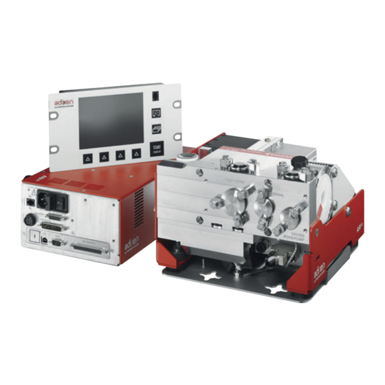
Integrable industrial leak detector
Hide thumbs
Also See for ASI 35:
- Operating instructions manual (154 pages) ,
- Maintenance instructions manual (37 pages) ,
- Operating instructions manual (48 pages)

Subscribe to Our Youtube Channel
Related Manuals for Pfeiffer Vacuum ASI 35


Summary of Contents for Pfeiffer Vacuum ASI 35
- Page 1 MAINTENANCE INSTRUCTIONS Translation of the Original ASI 35 Integrable industrial leak detector...
- Page 2 These operating instructions describe all models and variants of your product. Note that your product may not be equipped with all features described in this document. Pfeiffer Vacuum constantly adapts its products to the latest state of the art without prior notice. Please take into account that online operating instructions can deviate from the printed operating instructions supplied with your product.
-
Page 3: Table Of Contents
5.10 Flow reducer replacement Decommissioning Shutting down for longer periods Disposal 6.2.1 Restriction of Hazardous Substances (RoHS) 6.2.2 Electrical and Electronic Equipment (EEE) Malfunctions Operation monitoring Fault display Service solutions by Pfeiffer Vacuum Spare parts Tools Leak detector spare parts 3/40... -
Page 4: About This Manual
Keep the manual for future consultation. 1.1 Validity This maintenance manual is intended for customers of Pfeiffer Vacuum. It describes the maintenance procedures that the customer can perform on the respective product. This document has to be used in conjunction with the operating instructions of the product with the same name. -
Page 5: Instructions In The Text
About this manual 1.3.2 Instructions in the text Usage instructions in the document follow a general structure that is complete in itself. The required ac- tion is indicated by an individual step or multi-part action steps. Individual action step A horizontal, solid triangle indicates the only step in an action. ►... - Page 6 About this manual Electronic module For service centers use only Pu_GL : 1 Pu_N : 1 Mu_GL : 12856 Mu_N : 31 Mu_Cal : 1 Mu_LDS : 1800 (Example) This label provides information regarding firmware installed in the product. DD-MM-YY Factory Firmware /Logiciel usine Firmware name Firmware checksum...
-
Page 7: Abbreviations
About this manual This label indicates that the blanking plate fitted on the manual valve must be TO BE REMOVED BEFORE removed before using the leak detector. Keep for maintenance or storage USE OF LEAK DETECTOR TO BE KEPT FOR MAINTENANCE This label indicates that the product has been certified compliant with quality control upon leaving the factory. -
Page 8: Safety
► Maintain the distances specified by the manufacturer of the pacemakers. – Pfeiffer Vacuum recommends a safety distance of at least 130 mm between the pacemaker and the product. ► Avoid the influence of strong magnetic fields by means of magnetic field shielding. - Page 9 Safety WARNING Electric shock hazard Voltage and current can cause electric shock. Only skilled, authorized people may carry out maintenance work. ► Insulate and lock the power supply circuit by setting the switch to O. ► Disconnect the power supply cable from all power sources before working on the product and/or removing the covers.
-
Page 10: Precautions
Safety 2.3 Precautions Duty to provide information on potential dangers The product holder or user is obliged to make all operating personnel aware of dangers posed by this product. Every person who is involved in the installation, operation or maintenance of the product must read, understand and adhere to the safety-related parts of this document. -
Page 11: General Information
(see chap- ter “Spare parts”, page 34). ● To identify the product and communicate with Pfeiffer Vacuum look at the product's rat- ing plate. 3.2 Preparatory work The detector does not require any maintenance at the customer’s premises, except for the sub-assem- bly maintenance described in this manual. -
Page 12: Maintenance Frequency And Responsibilities
Maintenance frequency and responsibilities 4 Maintenance frequency and responsibilities Maintenance level 1 and 2 operations are described in this manual. Level 3 maintenance operations require a technician from the Pfeiffer Vacuum Service network. Operation Number of hours in use Level Site... - Page 13 Maintenance frequency and responsibilities How to contact us Product overhauls must be carried out by personnel with manufacturer training. Contact our nearest service center at the following e-mail address: support.service@pfeiffer-vac- uum.com. 13/40...
-
Page 14: Service - Maintenance
Service - Maintenance 5 Service - Maintenance 5.1 Cleaning ► Clean the cover(s) with a soft, lint-free cloth and a product that will not damage the paint, painted surfaces or the labels. 5.2 Detector powering off ► Wait 5 minutes before working on the detector, removing the cover, or moving the detector. Pump stop due to power failure When there is a mains power failure, the detector shuts down: it switches on again automatically when power is restored. -
Page 15: Accessing The Vacuum Module Components
Service - Maintenance 5.4 Accessing the vacuum module components Prerequisites ► Power off the leak detector (see chapter “Powering Off”). ► Disconnect the cables which link the vacuum module to the control panel and the electronic mod- ule. ► Remove the vacuum module from the installation. Set the module on a flat surface (clean workbench in a dust-free place). -
Page 16: Internal Calibrated Leak Replacement
Service - Maintenance 90° (2) Carefully unscrew the screws without removing them. (4) The fixing screw keeps the upper part raised. 1 Fixing screw and washer Fixing screws ► After any maintenance procedure which has required putting the module in the ‘Maintenance’ po- sition, never leave the module in this position. - Page 17 Service - Maintenance Calibrated leak disassembly 90° (1) Carefully unscrew the screws without removing them. (3) Never separate the temperature sensor from the calibrated leak. Calibrated leak reassembly 1. Follow the disassembly steps in reverse. 2. Update the parameters of the calibrated leak (see chapter “Calibrated leak” in the operating in- structions).
-
Page 18: Analyzer Cell Maintenance
Service - Maintenance 5.6 Analyzer cell maintenance Pollution of vacuum circuit components During maintenance operations for vacuum circuit components, avoid any contamination which could subsequently result in the degassing of the parts. Special caution must be ex- ercised to ensure cleanliness. To avoid this: ●... -
Page 19: Seal Replacement
Service - Maintenance Deflector Analyzer cell Fixing screw and washer Fixing screws Analyzer cell connector Distortion of the measurement results with non-compliant analyzer cell When it leaves the factory, the analyzer cell is set for the product in which it is installed. The use of an analyzer cell different from the original component requires settings. - Page 20 Service - Maintenance Disassembly F1 Filament 1 Fixing screw and washer F2 Filament 2 Fastening clips 1. Remove the detector analyzer cell (see chapter “Disassembly/reassembly of the analyzer cell”). 2. Remove the fixing screw and washer of the defective filament. 3.
-
Page 21: Maintenance Of The Turbomolecular Pump
Service - Maintenance 3. Reassemble the analyzer cell (see chapter “Disassembly/reassembly of the analyzer cell”). 4. Update the replaced filament maintenance counter from the menu (see chapter “Counters” in the operating instructions). 5.7 Maintenance of the turbomolecular pump 5.7.1 Wheel replacement In order to protect the turbomolecular pump from any involuntary inlet vent, the wheel of the pump can be replaced by a special screw (screw supplied with the leak detector). -
Page 22: Turbomolecular Pump Operating Fluid Reservoir Replacement
NOTICE The product may be damaged if an unauthorized operating fluid is used The pumps are tested at the factory using Pfeiffer Vacuum oil. Using any other oil may adversely af- fect the pump and its performance. ► It is essential that the oil recommended by the manufacturer is used. - Page 23 Service - Maintenance Operating fluid reservoir disassembly The pins of the spanner fit into the notches in the housing cover. Spanner for housing cover O-ring Housing cover The 2 flat screwdrivers in the circumferential groove of the operating fluid reservoir are positioned approximately 180°...
- Page 24 Service - Maintenance Capillary rod (x8) Operating fluid reservoir reassembly The operating fluid reservoir slides smoothly out of its container in the bearing support frame. The operating fluid reservoir sits freely in the pump. Capillary rod (x8) Operating fluid reservoir 24/40...
-
Page 25: Fan Maintenance
Service - Maintenance 13 Nm The pins of the spanner fit into the notches in the housing cover. Spanner for housing cover O-ring Housing cover 5.8 Fan maintenance 5.8.1 Replacing the fan of the vacuum module Prerequisite 1. Put the module in the 'Maintenance' position (see chapter “Access to the components of the vac- uum module”). -
Page 26: Replacing The Fan Of The Electronic Module
Service - Maintenance Reassembling the fan of the vacuum module (1) The positioning direction of the fan in the vacuum module must be respected. (5) Connect the fan harness, respecting the (+) and (-) polarities. Grid Electrical harness 5.8.2 Replacing the fan of the electronic module Prerequisite 1. -
Page 27: Electronic Module Air Filter Replacement
Service - Maintenance Reassembling the fan of the electronic module CLAC! (1) Position the 4 clamps retained during disassembly. (4) The direction of fitting must be respected. 5.9 Electronic module air filter replacement Prerequisite ► Power off the leak detector (see chapter “Powering Off”). Air filter disassembly 1 Protection grid Filter... - Page 28 Service - Maintenance Flow reducer disassembly (3) Check that the seal is still positioned on the vacuum module. (4) Save the seal for the new flow reducer. Fixing screws Flow reducer seal Sniffing module Purge flow reducer Seal Air filter reassembly ►...
-
Page 29: Decommissioning
This product bears the identification logo because it is subject to regulations on the management of Waste from EEE. The manufacturer shall only be required to take back EEE marked Pfeiffer Vacuum sold by Pfeiffer Vac- uum: ● EEE subject to applicable regulations for recycling end-of-life products;... - Page 30 To find out more about the collection solutions, contact ecosystem who will inform you of the best col- lection solution for your needs: www.ecosystem.eco For further details, consult the General Conditions of Sale available in French on the Pfeiffer Vacuum website. Product on sale outside of France...
-
Page 31: Malfunctions
Malfunctions 7 Malfunctions 7.1 Operation monitoring During operation, the user is notified of an incident on the detector control panel. Type of fault Control panel Warning Display of fault. Click on the pictogram to display the fault. Error Display of fault. Click on the pictogram to display the fault. -
Page 32: Service Solutions By Pfeiffer Vacuum
We are always focused on perfecting our core competence – servicing of vacuum components. Once you have purchased a product from Pfeiffer Vacuum, our service is far from over. This is often exactly where service begins. Obviously, in proven Pfeiffer Vacuum quality. - Page 33 Service solutions by Pfeiffer Vacuum 5. Prepare the product for transport in accordance with the provisions in the contamination declaration. a) Neutralize the product with nitrogen or dry air. b) Seal all openings with blind flanges, so that they are airtight.
-
Page 34: Spare Parts
Calibrated leak + valve 1/3 10-6, DN 25 ISO-KF FV4610 Silicon vacuum grease (100 g tube) 064600 Needlenose pliers 115396 Quick connect clamp, DN 20/25 ISO-KF 083264 Centering ring DN 25 ISO-KF (Perbunan) 068189 Detector packaging - ASI 35 123526 34/40... -
Page 35: Leak Detector Spare Parts
Spare parts 9.2 Leak detector spare parts Display Item Designation Comments 3G Control panel 122447S Option/Accessory 3G control panel cable Length 2 m A602394 Option/Accessory Length 5 m A458735 Option/Accessory Length 10 m 110881 Option/Accessory Power and electrical supply Item Designation Comments 2 m mains cable - Italy 104758... - Page 36 Spare parts Item Designation Comments A459291 Air filter 118699 3 m gauge cable (37-pin Sub-D) A333746 10 m gauge cable (37-pin Sub-D) A333747 Measurement Item Designation Comments Filament 114864S Sold individually NBR seal 114346 Sold individually Internal calibrated leak 121528S Option/Accessoire (Calibration) Sniffer kit 123529...
- Page 37 PM 143 740 -T Vacuum block Item Designation Comments Blanking plate with storage valve 123861 M5 silencer (sintered bronze) 108449 Flow reducer - ASI 35 123525 Option/accessory (Sniffer) Pipes - Connections - Seals Designation Comments Quick-connect clamp DN 10/16 ISO-KF 110BSR016...
- Page 38 Spare parts Designation Comments NBR O-ring DN 16 ISO-KF 106021 DN 25 ISO-KF 106022 O-ring support ring DN 16 ISO-KF 120ZRG016 DN 25 ISO-KF 120ZRG025 Stainless steel mesh filter 70 µm DN 16 ISO-KF 072721 DN 25 ISO-KF 072857 NBR seal - 3G analyzer cell 114346 Connector for Smart probe 123180...
- Page 39 Spare parts 39/40...
Need help?
Do you have a question about the ASI 35 and is the answer not in the manual?
Questions and answers