Pfeiffer Vacuum ASM 390 Operating Instructions Manual
Leak detector
Hide thumbs
Also See for ASM 390:
- Operating instructions manual (79 pages) ,
- Additional installation, operation and maintenance instructions (34 pages) ,
- Maintenance instructions manual (32 pages)

Related Manuals for Pfeiffer Vacuum ASM 390


Summary of Contents for Pfeiffer Vacuum ASM 390
- Page 1 OPERATING INSTRUCTIONS Translation of the Original ASM 390 - ASM 392 Leak detector...
- Page 2 These operating instructions describe all models and variants of your product. Note that your product may not be equipped with all features described in this document. Pfeiffer Vacuum constantly adapts its products to the latest state of the art without prior notice. Please take into account that online operating instructions can deviate from the printed operating instructions supplied with your product.
-
Page 3: Table Of Contents
Table of contents Table of contents About this manual Validity 1.1.1 Products concerned 1.1.2 Applicable documents Target group Conventions 1.3.1 Pictographs 1.3.2 Instructions in the text 1.3.3 Labels 1.3.4 Abbreviations Safety General safety information 2.1.1 Safety instructions 2.1.2 Precautions Intended use Foreseeable misuse Transportation and Storage Product receipt... - Page 4 Table of contents 7.6.3 Calibration in hard vacuum test mode with a pumping system in parallel 7.6.4 Calibration in sniffing test with internal calibrated leak 7.6.5 Calibration in sniffing test with external calibrated leak 7.6.6 Calibration in sniffing test on concentration Zero Function Touch screen 7.8.1 Navigation...
- Page 5 Table of contents 8.5.4 Screen settings 8.5.5 Access – Password Advanced menu 8.6.1 Leak Detection: Start Up timer 8.6.2 Leak Detection: Background suppression 8.6.3 Leak Detection: Crossover pressures 8.6.4 Leak Detection: Calibration 8.6.5 Leak Detection: Analyzer cell 8.6.6 Leak Detection: Internal Pirani gauge calibration 8.6.7 Leak Detection: External gauge 8.6.8 Input/Output: Serial link 1 and Serial link 2 8.6.9 Input/Output: I/O connector...
- Page 6 List of tables List of tables Tbl. 1: Accessories Tbl. 2: Environmental conditions Tbl. 3: Units of pressure and their conversion Tbl. 4: Gas throughputs and their conversion Tbl. 5: Default settings: ‘Set Points’ menu Tbl. 6: Default settings: ‘Test’ menu Tbl.
-
Page 7: About This Manual
Keep the manual for future consultation. 1.1 Validity This operating instructions is a customer document of Pfeiffer Vacuum. The operating instructions de- scribe the functions of the named product and provide the most important information for the safe use of the device. The description is written in accordance with the valid directives. The information in this op- erating instructions refers to the product's current development status. -
Page 8: Instructions In The Text
About this manual Note Key point on the illustration to be checked Stated tightening torque to be applied 1 2 3 Respect the chronological order of operations and/or assembly/disassembly direction 1.3.2 Instructions in the text Usage instructions in the document follow a general structure that is complete in itself. The required ac- tion is indicated by an individual step or multi-part action steps. -
Page 9: Abbreviations
About this manual This label indicates that the product is subject to regulations for the treatment of electrical and electronic equipment waste (refer to the EC declaration of con- formity for the product). This label indicates the MAC address for the options installed in the product. HLD1302577 - RS232 Bluethooth MAC address XXXXXX / None... -
Page 10: Safety
Safety 2 Safety 2.1 General safety information The following 4 risk levels and 1 information level are taken into account in this document. DANGER Immediately pending danger Indicates an immediately pending danger that will result in death or serious injury if not observed. ►... - Page 11 Safety WARNING Risk of electric shock in case of contact with products that are not electrically isolated When powering off _mains switch to O_, certain components located between the mains connection and the circuit breaker will still contain an electric charge (live). There is a risk of electric shock in case of contact.
-
Page 12: Precautions
Safety CAUTION Risk of pinching fingers When handling the cover or the work surface, there is a risk of fingers becoming pinched. ► Keep hands away from the sides while handling the cover. ► Keep fingers away from the fastening latches when closing the cover or the work surface. NOTICE Incorrect use of purge A leak detection operation should be carried out on parts or equipment that contain any trace of sub-... -
Page 13: Intended Use
Safety 2.2 Intended use The leak detector is designed to detect and/or quantify a possible installation or component leak by searching for the presence of a tracer gas in the pumped gases. Only the tracer gases identified in this manual may be used. The product may be used in an industrial environment. -
Page 14: Transportation And Storage
Transportation and Storage 3 Transportation and Storage 3.1 Product receipt Condition of the delivery ● Check that the product has not been damaged during transport. ● If the product is damaged, take the necessary measures with the carrier and notify the manufacturer. ►... -
Page 15: Handling
► Move the product using the handle or the gripping area located at the front of the work surface. ► Do not move the product using the bumper, the control panel (or its arm) or the inlet port. 3.4 Storage Pfeiffer Vacuum recommends storing the products in their original transport packaging. 15/98... - Page 16 Transportation and Storage New product storage ► Leave the product in its packaging. ► Leave the blanked-off flange in place on each port. ► Store the module in a clean and dry environment according to the permitted temperature condi- tions (see chapter “Technical characteristics”). ►...
-
Page 17: Product Description
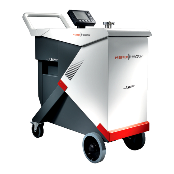
They are designed for applications for which ultra-cleanliness and a high pumping speed are essential (semiconductors, coating, etc.). ● ASM 390: with a tracer gas pumping speed of more than 10 l/s, the ASM 390 provides fast re- sponse time. -
Page 18: Connection Interface
Product description 4.2 Connection interface 11 12 Hose holder attachment point USB plug (USB) Work surface 9-pin D-Sub RS-232 serial link connector (SERIAL) Detector inlet port (inlet) 37-pin D-Sub I/O communication interface connector (INPUTS/OUTPUTS) Standard remote control connec- 15-pin D-Sub I/O communication interface connector (INPUTS/OUTPUTS) SD Card Inlet vent connector... -
Page 19: Control Panel Description
Product description 4.3 Control panel description START STAND-BY Standard remote control connection (accessory). Changing the application screens: return to the home page (“standard” screen) from any menu. Changing the level of function keys. START/STAND-BY button Test Start/Stop. Quick access to functions (see chapter “Function keys”). Displaying a function key level: starting the function or displaying a sub-menu by touching the screen. -
Page 20: Installation
Installation 5 Installation 5.1 Detector installation NOTICE Leak detector ventilation In cases of poor ventilation, there is a risk of deterioration of the detector’s internal components by heating. ► Comply with the ambient operating temperature. ► Do not obstruct the ventilation grids. ►... -
Page 21: Storage
Installation Hose holder Flexible tube 5.4 Storage The leak detector includes a lockable storage box and flexible storage trays. The batch of partitions delivered with the product allows for compartmentalization of the storage box for the user’s convenience. 1 Storage box Flexible storage tray Storage box cover locking It is possible to lock the cover of the storage box using a padlock (padlock not included, at the custom-... -
Page 22: Purge And Inlet Vent Connection
Installation The use of a small flat tool (a screwdriver, for example) is necessary to remove the cover plate from the access window in order to provide access for the locking plate. Location for padlock Access window (cover plate removed) 3a Access window (cover plate not removed) 5.5 Purge and inlet vent connection 5.5.1 Standard equipment... -
Page 23: Exhaust Connection
Installation WARNING Risk of injury due to elevated pressure in a pipe The neutral gas supply circuit is pressurized. There is a risk of explosion, implosion, or rupture of the components during maintenance operations, which is likely to cause injuries and to damage the detector. To work on the product without this risk, the user should lock the neutral gas supply circuit. -
Page 24: Part/Installation To Be Tested Connection
Installation NOTICE Risk of electromagnetic disturbance Voltages and currents can induce a multitude of electromagnetic fields and interference signals. In- stallations that do not comply with the EMC regulations can interfere with other equipment and the environment in general. ► Use shielded cables and connections for the interfaces in interference-prone environments. Electrical safety The leak detector is Class 1 equipment and therefore must be earthed. -
Page 25: Commissioning
Commissioning 6 Commissioning 6.1 Detector start-up 1. Connect the main power supply cable. 2. Set the main switch/circuit breaker to I. 3. For first start-up: set the language, unit, date and time (the user can modify these settings at a later time). 4. -
Page 26: Operation
Operation 7 Operation 7.1 Use conditions WARNING Risk of injury due to the use of hydrogen as tracer gas Hydrogen can be used as a tracer gas for leak detection. Depending on its concentration, in the worst scenario, there may be a risk of explosion. ►... -
Page 27: Test Start/Stop
Operation Type of fault Control panel Warning Display of fault. Click on the pictogram to display the fault. Error Display of fault. Click on the pictogram to display the fault. Critical error Display of the message “Critical error - E244”. Contact our service center. -
Page 28: Test Launched Automatically Upon Start-Up
Operation 3. Depending on the model of the detector, select the model of the sniffer probe used (see chapter “Type of probe”). 4. Set the reject point if necessary (see chapter “Sniffing reject point”). 5. Put the detector on ‘Stand-by’ mode. 6. -
Page 29: Calibration In Hard Vacuum Test Mode With Internal Calibrated Leak
Operation Use a calibrated leak in the range of ≈ 10 mbar · l/s (≈ 10 Pa · m /s). In the case of intensive use of the detector, a spare internal calibrated leak is recommend- ed. By default, the detector can be calibrated with an external calibrated leak. External calibrated leak The operator must use a calibrated leak containing the tracer gas selected ( He or H... -
Page 30: Calibration In Sniffing Test With Internal Calibrated Leak
Operation Corrected leak rate = target value = measured leak value x correction factor 1. Allocate a function key to [Correction] (see chapter “Function keys”). 2. Select the ‘hard vacuum’ test method (see chapter “Test method”). 3. Press the START/STAND-BY button to start a test. 4. -
Page 31: Calibration In Sniffing Test On Concentration
Operation 1 DN 16 ISO-KF or DN 25 ISO-KF adapter Sniffer probe 2 Fixing screws Calibrated leak 1. Attach the adaptor to the external calibrated leak used for the calibration with a centering ring and a clamp. 2. Press the [Auto.Cal] function key to start a calibration. 3. -
Page 32: Touch Screen
Operation 7.8 Touch screen The touch screen is interfaced with the detector and is used to: ● display information about the test, ● access the available functions, ● set the detector's parameters. 4 application screens are provided to the user to access this data. The user can hide and/or change some screens in the loop (see chapter “Application Windows”). -
Page 33: Navigation
Operation 7.8.1 Navigation Symbols Function deactivated (OFF) Function activated (ON) Authorized access without password Access locked: access with password "Pixelated" key: access prohibited for the product xxxxxxxx “Grey” key: access settings or function “White” key: key not customiable, for information “Measurement information” key: to display the measured leak rate Arrows for navigating within the menus Access to the error/warning window Value selected is customizable... -
Page 34: Graph Screen
Operation Item Function Zero function 2 decade bargraph display Cell or external gauge pressure bargraph display ‘Inlet vent’ function status indicator ‘Mute’ function status indicator Indicator : error/warning message to be consulted ‘Purge’ enabled function status indicator Current status of the detector Detection mode Detector inlet pressure bargraph display (unit consistent with the leak rate unit) Leak rate Bargraph display (adjustable scale) -
Page 35: Graph Screen: Graph Parameters
Operation Item Function Plot of the tracer gas leak rate (in red) Time scale Scale of the tracer gas leak rate (in red) 1) Adjustable scale by pressing the graph 7.8.4 Graph screen: graph parameters ► Press on the screen to access the graph parameters. Access: Press on the screen to access the graph parameters. -
Page 36: Graph Screen: Scales
Operation ● if the new recording is to be added to the recordings in the memory [OK]. ● if the new recording is to delete and replace the recordings in the memory [Cancel]. Configuration Press the graph, then [Record], to modify the recording parameters Choice - Setting limit Duration To be set... -
Page 37: Graph Screen: Saving A Recording
Operation Period of time displayed on the screen Setting the automatic scale Setting the measured leak rate scale Setting the inlet pressure scale Displaying/Hiding the inlet pressure Displaying/Hiding the measured leak rate Activating/Deactivating the automatic scale Access: Press the graph and [Scale] to modify the graph parameters. Choice - Setting limit Display... -
Page 38: Graph Screen: Viewing A Recording
Operation The saved .bmp and .txt files include only the measurement points displayed on the screen: ● to include all points, you must be positioned on the relevant plot (without zooming). ● if a zoom was carried out before saving, the zoom will apply only to the points of the selected area. -
Page 39: 10Settings Screen
Operation 1. Press twice on the zoom to return to the original graph. – The 2 press should always be done to the left of the 1 on the screen: see the example above. Measurement Exact measurement of a point, only available on a recording. 1 Navigation between next/previous recorded points Moment the measurement took place in re- lation to the start of the recording... -
Page 40: 11Vacuum Circuit Screen
Operation Temporary access to a locked menu Temporary access: after returning to the main screen, the menu is once again locked. ► See chapter “Access - Password”. 7.8.11 Vacuum circuit screen The vacuum circuit corresponds to the detector’s schematic diagram. The vacuum circuit displayed is specific to each detector model. The vacuum circuit varies depending on the status of the valves, but does not make it possible to man- age the valves. -
Page 41: Settings
Settings 8 Settings The Settings screen allows the user to access 6 menus for configuring the product to use specifications. See chapter “Settings Screen”. Functions by menu SET POINTS menu ● Audio alarm ● Digital voice ● Pollution function ● Hard vacuum reject point ●... -
Page 42: Set Points Menu
Settings Functions by menu CONFIGURATION menu ● Unit/Date/Language ● Function keys ● Application windows ● Screen settings ● Access - Password ADVANCED menu Advanced functions reserved for specific detector uses. ● Leak Detection: Start-up timer ● Leak Detection: Background suppression ●... -
Page 43: Pollution Function
Settings For quick access from the main screen, configure a function key to [VOICE] (see chapter “Function keys”). From the main screen, use the [MUTE] key to simultaneously cut off the sound alarm and the digital voice. On the control panel, the red cross on the pictograph indicates that the “Mute” function is enabled. -
Page 44: Probe Clogged Threshold
Settings Access: Settings Screen + Menu [Set Points] [Sniffing Set Points] Choice - Setting limit Reject point To be set 1 · 10 – 1 · 10 The reject point is the acceptance threshold for parts. ● Measured leak rate < reject point: part accepted ●... -
Page 45: Test Menu
Settings Access: Settings Screen + Menu [Set points] [Other Pressure Set pts] Choice - Setting limit Pressure reject point 1/2 To be set 5 · 10 – 3 · 10 Pressure reject point 1 must always be greater than pressure reject point 2 1) Initial setting: see chapter “Tree diagram of the Settings menu”... -
Page 46: Test Mode
Settings The leak rate displayed takes into account the correction factor applied. Use of the correction factor must not replace calibration. Access: Settings Screen + Menu [Test] Choice - Setting limit HV correction To be enabled Enabled Disabled To be set 1 ·... -
Page 47: Probe Type
Settings By default, the leak detector is set to work in a hard vacuum test, in the most sensitive test mode: this setting meets the majority of users’ needs. 8.2.4 Probe type This menu is used to select the sniffer probe type used in sniffing (see chapter “Accessories”). Access: Settings Screen + Menu [Test] Choice - Setting limit Probe type... -
Page 48: Memo Function
Settings Access: Settings Screen + Menu [Test] [Inlet Vent] Choice - Setting limit Inlet vent To be selected Operator ● Operator: the inlet vent is carried out by the user by pressing on the [In- Automatic let Vent] function key or on the corresponding pictograph on the main screen. -
Page 49: Zero Activation
Settings 8.2.8 Zero activation This function helps the user to identify very small leak rate variations in the surrounding background noise or to dilate small measured leak rate fluctuations on the analog display. When the zero function is activated, a 2-decade bargraph appears on the main screen. Access: Settings Screen + Menu [Test] [Zero Activation] Choice - Setting limit Activation... -
Page 50: 10Regeneration
Settings Access: Settings Screen + Menu [Test] [Bypass Option] Choice - Setting limit Mode To be selected No Bypass ● No Bypass = External Bypass pump installed but not enable Quick pumping ● Quick pumping = External Bypass pump active only during roughing Partial Flow ●... -
Page 51: 11Massive Mode
Settings 8.2.11 Massive mode This mode allows the detector to perform a test ( He only) on a very large leak when the detector has not shifted to Gross Leak mode and remains in roughing. Massive mode can only be used if an external gauge is selected (see chapter “Leak Detection: External gauge”). -
Page 52: Filament Parameters
Settings For quick access from the main screen, configure a function key to [TRACER GAS] (see chapter “Function keys”). Hydrogen test WARNING Risk of injury due to the use of hydrogen as tracer gas Hydrogen can be used as a tracer gas for leak detection. Depending on its concentration, in the worst scenario, there may be a risk of explosion. -
Page 53: Maintenance Menu
Settings Access: Settings Screen + Menu [Spectro] [Calibrated leak] Choice - Setting limit Unit To be selected mbar · l/s Unit of calibrated leak used for calibration Pa · m Torr · l/s atm · cc/s Leak value To be set 1 ·... -
Page 54: Timers
Settings 8.4.2 Timers For quick access from the main screen, configure a function key to [Maintenance] (see chapter “Function keys”). Access: Settings Screen + Menu [Maintenance] [Timers] Choice - Setting limit Detector Read only Detector running time Filament 1 Read only Running time for filament 1 Function to be launched 1. -
Page 55: Detector Information
Settings Additional information about Cycles Access: [xxxx Cy/xxxx Cy] for the ‘Cycle’ parameter Choice - Set- ting limit Cycles Read only Percentage of the number of cycles carried out since the last reset compared to the configured cycle interval. Counter Read only Number of cycles carried out since the last counter reset. -
Page 56: Pump Information
Settings Access: Settings Screen + Menu [Maintenance] [Detector Information] Calibration Type of calibration configured Tracer gas selected Filament Filament used (Status of filament used, detector on) Status Filament use rate (100% = new filament) Last Calib. Date of last calibration List of activated functions (blank line if none) Next maintenance Time before the next maintenance to be performed... -
Page 57: Calibration History
Settings Access: Settings Screen + Menu [Maintenance] [Events History] 1 Exporting the history in .csv format to the SD card Date and time of the event 2 Event code Description of the event An event can be an error (Exxx), a warning (Wxxx) or an information (lxxx). ●... -
Page 58: Secondary Pump And Analyzer Cell Maintenance
Settings Prerequisite(s) ● Detector on “Standby” mode ● “Automatic” inlet vent Access: Settings Screen + Menu [Maintenance] [Burn-in] NOTICE Risk of pollution ► Before starting this function, make sure that the leak detector is in an environment free of tracer gas pollution. -
Page 59: Configuration Menu
Settings 8.5 Configuration menu 8.5.1 Time – Date – Unit – Language Access: Settings Screen + Menu [Configuration] [Unit/Date/Language] Choice - Setting limit Unit mbar · l/s To be selected The set points/values set are not automatically converted to the Pa · m new unit if the unit changes: they must be updated by the user. -
Page 60: Application Windows
Settings START STAND-BY Using the function keys, the user can be given access to a limited number of functions and to use a password to lock unauthorized functions on the “Settings” menu. These are suffi- cient to manage the detector. To allow the user to use only the START/STAND-BY key, do not allocate a function to the function keys and lock the “Settings”... - Page 61 Settings 1 Order of screens displayed with the Available screens 2 Display (✔)/Hide (✘) for application windows Main screen (standard) always displayed Access: Access: Settings Screen + Menu [Configuration] [Application windows] Choice - Setting limit Standard Read only Activated by default Main screen display Read only Order in the loop...
- Page 62 Settings Example 1 ● The Synoptic screen moved from position 3 to 4 in the loop. Example 2 ● The Graph screen is hidden and the overall order is updated. Example 3 ● The Graph screen is once again available in posi- tion 4 in the loop.
-
Page 63: Screen Settings
Settings 8.5.4 Screen settings Access: Access: Settings Screen + Menu [Configuration] [Screen settings] Choice - Setting limit Brightness To be selected High Contrast To be set 0 – 100 Panel Off To be selected None The screen is in sleep mode when the back light goes off (black screen). 15 min The device appears to be off, but this is not the case! Simply touching the 30 min... - Page 64 Settings Menu access Example 1: locking of Set Points, Spectro and Advanced menus Example 2: display of locked menus (Set Points, Spectro and Advanced) on the Settings screen The user can prevent access for one or more menus on the Settings screen by locking them. To access a locked menu, the user is asked to provide the password.
- Page 65 Settings User level Restricted access Medium access Full ac- cess Display of meas- Display only in test Display only in test ured leak rate and reject setpoint dis- played only in test Access to settings menus No setting possible No setting possible without a pass- without a password word (temporary access allowed) (temporary access al-...
-
Page 66: Advanced Menu
Settings Access level change For a user with restricted or medium access. For a user with full access 1. Press and hold the 1. Access: Settings Screen + button until the Settings screen Menu [Configuration] [Access/ is displayed with all of the locked menus. Password] 2. -
Page 67: Leak Detection: Background Suppression
Settings Access: Settings Screen + Menu [Advanced] [Leak Detection] [Start Up Timer] Choice - Setting limit Start Up Timer To be set 0 – 1h 1) Initial setting: see chapter “Tree diagram of the Settings menu” 8.6.2 Leak Detection: Background suppression This function is used to suppress the detector’s intrinsic background. -
Page 68: Leak Detection: Analyzer Cell
Settings Access: Settings Screen + Menu [Advanced] [Leak detection] [Calibration] Choice - Setting limit Calibration To be selected Operator ● Operator Start-up Calibration initiated by the user pressing the [AUTOCAL] function key. Manual If the calibration is not begun within 20 minutes of switching the detector on, the message “Detector ready for calibration”... -
Page 69: Leak Detection: Internal Pirani Gauge Calibration
Settings Access: Settings Screen + Menu [Advanced] [Leak detection] [Analyzer cell] Choice - Set- ting limit Filament Selected To be selected Filament used for the measurement (2 filaments in the analyzer cell). Filament To be selected Activation (ON) or deactivation (OFF) of the filament in use for the measurement. -
Page 70: Input/Output: Serial Link 1 And Serial Link
Settings Prerequisite(s) ● Detector equipped with a 37-pin I/O communications interface (see chapter “Accessories”) ● Massive Mode deactivated ● Inlet pressure source: external ● Possible gauges Type of gauge detected by the detector Gauge model Linear gauge Capacitive Linear CMRxxx Piezo Linear APRxxx... -
Page 71: Input/Output: I/O Connector
Settings Access: Settings Screen + Menu [Advanced] [Input/Output] then [Serial Choice - Setting limit link 1] or [Serial link 2] Type To be selected Serial Link type depending on use: see the operating instructions of the accessory/option to be used. Network 3) 4) Not used... -
Page 72: 11Service
Settings Access: Settings Screen + Menu [Advanced] [SD Card] Load Parameters De- Function to be launched tector Loading of the saved parameters (configuration) on the control panel SD card. Prerequisites: detector power on and in ‘Stand-by’ mode. After loading, the following parameters should be configured by the user: language, serial link, date, time, temperature unit and pressure unit. -
Page 73: Maintenance/Replacement
Maintenance/Replacement 9 Maintenance/Replacement Maintenance intervals and responsibilities The detector maintenance operations are described in the Maintenance instructions for the detector. The manual specifies: ● maintenance intervals, ● maintenance instructions, ● shutting the product down, ● tools and spare parts. 73/98... -
Page 74: Accessories
Accessories 10 Accessories Accessory Description Part Number Standard remote control Unit: mbar · l/s 106688 Unit: Torr · l/s 108881 108880 Unit: Pa · m 106690 Unit: Pa · m Japan model RC 10 remote control (wireless) 124193 Standard sniffer probe Refer to Pfeiffer Vacuum catalogue Standard sniffer probe extension... -
Page 75: Technical Data And Dimensions
Technical data and dimensions 11 Technical data and dimensions 11.1 General Databases of technical characteristics of Pfeiffer Vacuum leak detectors: ● Technical characteristics according to: ─ AVS 2.3: Procedure for calibrating gas analyzers of the mass spectrometer type ─ EN 1518: Non-destructive testing. Leak testing. Characterization of mass spectrometer leak detectors ─... -
Page 76: Units Of Pressure
Technical data and dimensions 11.3 Units of pressure Unit mbar Torr / mm Hg mbar 0.75 1 · 10 1000 1000 1 · 10 0.01 0.01 1 · 10 1 · 10 7.5 · 10 0.75 1 · 10 0.01 1000 Torr / mm Hg 1.33 133.32... -
Page 77: Appendix
Appendix 12 Appendix 12.1 Tree diagram of the Settings menu Next tables indicate the default settings for the leak detector. When the leak detector is switched off, values and parameters are saved for the next start-up. Set point setting 1 Exponent setting Mantissa tenth setting 2 Mantissa unit setting Access: Settings Screen + Menu [Setpoints]... - Page 78 Appendix Access: Settings Screen + Menu [Setpoints] Choice - Setting limit Other Pressure Set Points Pressure Set Point #1 5 · 10 – 3 · 10 (If 37-pin I/O) +1 1) 2 · 10 Pressure set point #2 5 · 10 –...
-
Page 79: Tbl. 6: Default Settings: 'Test' Menu
Appendix Access: Settings Screen + Menu [Test] Choice - Setting limit Zero Activation Activation None Operator Automatic Zero Exit (if operator) Press once Press > 3 s Setting Trigger Timer (If automatic) Set point Setting If Timer 0 – 1 h 10 s If Set Point 1 ·... -
Page 80: Tbl. 7: Default Settings: 'Spectro' Menu
Appendix Access: Settings Screen + Menu [Spectro] Choice - Setting limit Calibrated leak Tracer Gas Helium 4 Helium 3 Hydrogen Type Internal External Concentration Unit mbar · l/s Pa · m Torr · l/s atm · cc/s Leak Value Calibration valve Open Closed Loss Per Year (%) - Page 81 Appendix Access: Settings Screen + Menu [Maintenance] Choice - Setting limit Detector 1) 2) Timers Detector 1) 2) Filament 1 Timer (h) 1) 2) Reset counter Function launching Filament 2 Timer (h) 1) 2) Reset counter Function launching Calibrated Leak Cycles Timer (h) 1) 2)
-
Page 82: Tbl. 8: Default Settings: 'Maintenance' Menu
Appendix Access: Settings Screen + Menu [Maintenance] Choice - Setting limit Maintenance Function launching Secondary Pump and Cell Last Mainte- Maintenance work 1 Date nance Total hours Inspected by Maintenance work 2 Date Total hours Inspected by Maintenance work 3 Date Total hours Inspected by... - Page 83 Appendix Access: Settings Screen + Menu [Configuration] Choice - Setting limit Application win- Standard Window Leak rate bar- Zoom on Set dows Parameters graph Point (main screen) Low Decade 1 · 10 – 1 · 10 1 · 10 +12 1) High Decade 1 ·...
-
Page 84: Tbl. 9: Default Settings: 'Configuration' Menu
Appendix Access: Settings Screen + Menu [Configuration] Choice - Setting limit Access / Pass- Password 0 – 9999 word 5555 ‘Set Points’ menu access Lock Unlock ‘Test’ menu access Lock Unlock ‘Spectro’ menu access Lock Unlock ‘Maintenance’ menu access Lock Unlock ‘Configuration’... - Page 85 Appendix Access: Settings Screen + Menu [Advanced] Choice - Setting limit Leak detection Start-Up Timer 0 – 1h 10 s Background Activation Suppression Crossover Gross Leak Pressures Normal High Sensitivity Calibration Calibration Operator Start-up Manual Calibration Checking Operator checking Automatic Frequency (If Cycles 0 –...
- Page 86 Appendix Access: Settings Screen + Menu [Advanced] Choice - Setting limit Input/Output Serial link 1 Type Serial (15-pin I/O) Parameters Mode Basic Spreadsheet Advanced Export. Data RC 500 WL RC 500 HLT 5xx Ext. Module HLT 2xx Handshake None XOFF Power Pin 9 Serial Link 2 Type...
- Page 87 Appendix Access: Settings Screen + Menu [Advanced] Choice - Setting limit Input/Output Serial Link 2 Type Not used (37-pin I/O) Network Parameters Mode Basic Spreadsheet Advanced Export. Data HLT 5xx Handshake None XOFF I/O Connector Quick View I/O set in the 37-pin D- Sub connector Analog output Digital input...
-
Page 88: 15-Pin Input/Output Communication Interface
Appendix Access: Press the graph, then [Range] Choice - Setting limit Leak Rate Display status Enabled Disabled Setting (If enabled) Low Decade - 10 1 · 10 0 1) High Decade - 10 -4 1) 1 · 10 Pressure Display status Enabled Disabled Setting (If enabled) -
Page 89: 2Interface
Appendix Outputs Logics Test threshold crossed ASM xxx: Selected test mode reached ASI xx: Detector ready Analogs Mantissa (0/10 V) Leak rate (logarithmic) 5 VDC - 750 mA max. Exponent (0/10 V) Mass 1 - 2 - 3 - 4 - 13 Headset Headset+ Headset-... -
Page 90: 5Formulas
Appendix 12.2.5 Formulas Mantissa (1/10 V) The “Mantissa” output corresponds with the leak rate mantissa. Formula U = Voltage measured (V) on analog output Mantissa = U Examples ● U = 3.5 V -> Mantissa = 3.5 ● U = 6.9 V -> Mantissa = 6.9 Exponent (0/10 V) The “Exponent”... -
Page 91: Rs-232 Serial Link
Appendix Logarithmic (0/10 V) Examples Example 1 Low decade at 10 (0 V = 1 · 10 ) -> D = -12 ● V = 3.91 V -> Leak rate = 10 (3,91 - 3) x 10 (3 - 12) = 8.13 ·... -
Page 92: 1Cable Characteristics
Appendix 12.3.1 Cable characteristics Refer to the RS-232 serial link operating instructions (see chapter “Applicable documents”). 12.3.2 Interface See chapter “Connection interface”. 12.3.3 Setting From the "Settings" screen, press [Advanced] [Input/Output] then [Serial Link 1] or [Serial Link 2] . Type Set the type of serial link 'Serial'. Parameter Set the serial link mode. - Page 93 Appendix Mode Description RC 500 WL Use of a wireless remote control (model RC 500 WL). 5 V power supply available. RC 500 Use of a wired remote control (model RC 500). 24 V power supply available HLT 5xx Protocol for compatibility with the HLT 5xx detector protocol. 5 V power supply available.
-
Page 96: Declaration Of Conformity
● Restriction of the use of certain hazardous substances 2011/65/EU ● Waste of Electrical and Electronic Equipment 2012/19/EU The person responsible for compiling the technical file is Mr. Arnaud Favre, Pfeiffer Vacuum SAS, 98, avenue de Brogny B.P. 2069, 74009 Annecy cedex. - Page 97 97/98...
Need help?
Do you have a question about the ASM 390 and is the answer not in the manual?
Questions and answers