Pfeiffer Vacuum ASM 310 Operating Instructions Manual
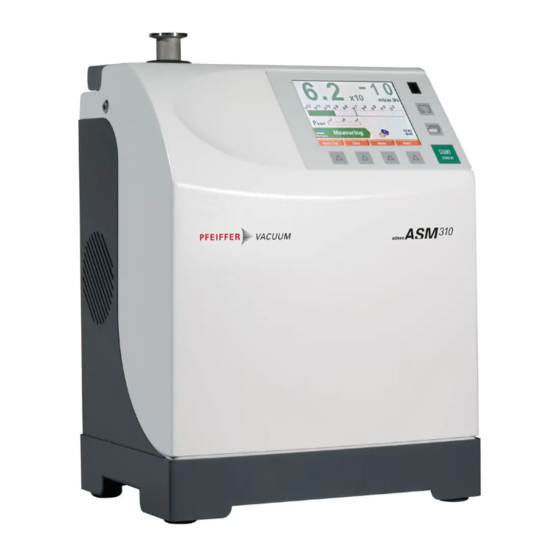
Portable leak detector
Hide thumbs
Also See for ASM 310:
- Condensed user's manual (2 pages) ,
- Operating instructions manual (98 pages) ,
- Maintenance instruction (36 pages)

Subscribe to Our Youtube Channel
Related Manuals for Pfeiffer Vacuum ASM 310


Summary of Contents for Pfeiffer Vacuum ASM 310
- Page 1 OPERATING INSTRUCTIONS Translation of the original instructions ASM 310 Portable leak detector...
-
Page 2: Table Of Contents
Table of contents Table of contents About this manual ..........5 1.1 Validity. - Page 3 Table of contents 6.4 Monitoring operation ......... 28 6.5 Shutdown the detector .
- Page 4 Table of contents 11.1 General ........... 65 11.2 Technical data .
-
Page 5: About This Manual
About this manual Validity This operating manual is for customers of Pfeiffer Vacuum. It describes the functioning of the designated product and provides the most important information for safe use of the unit. The description follows applicable EU guidelines. All information provided in this operating manual refers to the current state of the product's development. -
Page 6: Conventions
About this manual Conventions 1.2.1 Safety instructions Operating manual safety instructions Pfeiffer Vacuum are based on the UL, CSA, ANSI Z-535, SEMI S2, ISO 3864 and DIN 4844 certification standards. This document de- scribes the following information and danger levels: DANGER Imminent danger Indicates an imminent hazardous situation that will result in death or serious injury. -
Page 7: Pictographs
About this manual 1.2.2 Pictographs Prohibition of an action to avoid any risk of accidents, the disregarding of which may result in serious accidents Warning of a displayed source of danger in connection with operation of the unit or equipment Command to perform an action or task associated with a source of dan- ger, the disregarding of which may result in serious accidents 1.2.3... - Page 8 About this manual Quality: certifies that the product has been certi- fied compliant with quality control upon leaving the factory. Indicates whether the Bluetooth, Wi-Fi or Ether- HLD1302577 - RS232 net options have been installed on the products, Bluetooth MAC address and their MAC addresses.
-
Page 9: Safety
Safety Safety Safety precautions Obligation to inform Any person responsible for installing, using or maintaining the product must first read the security instructions in this operating manual and comply with them. It is the operating customer’s responsibility to protect all operators against the dan- gers associated with the product, with the media pumped and with the entire instal- lation. -
Page 10: Protective Equipment
Safety Only qualified personnel trained in safety rules (EMC, electrical safety, chemical pol- lution) may carry out the installation and maintenance described in this manual. Our service centers can provide the necessary training. Do not remove the blanked-off flange from the inlet port while the product is not in use. Do not expose any part of the human body to the vacuum. -
Page 11: Improper Use
Safety Only the tracer gases identified in this manual may be used. The parts to be tested must imperatively be clean and dry. The product may be used in an industrial environment. Improper use Improper use will cause all claims for liability and warranties to be forfeited. Improper use is defined as usage for purposes deviating from those mentioned above, especially: pumping harsh, chemical, corrosive, inflammable, reactive, toxic or explosive fluids pumping of liquids... -
Page 12: Transport And Storage
Transport and storage Transport and storage Upon delivery, check that the product has not been damaged during transport. If the product is damaged, take the necessary measures with the carrier and notify the manu- facturer. In all situations we recommend: Keeping the product in its original packaging so it stays as clean as it was when dis- patched by us. -
Page 13: Transport And Handling
We recommend that you use the transport case (accessory) that was specially designed for the ASM 310 (see 10). 8 0 0 Remove the foam from the case (1). Put the ASM 310 all the way in (2). Store the accessories in the foam (optional) (3). Replace the foam (4). 3.3.2... - Page 14 Transport and storage 1 Fixing screws delivered with the cart CAUTION Maximum authorised weight on the transport cart: 26 kg You must attach the cart to the leak detector.
-
Page 15: Product Description
1 15-pin D-sub plug not wired for I/Os. 4.1.2 Variants The ASM 310 is the lightest leak detector of its category, ultra compact and truly portable. It is the ideal detector for all maintenance applications when mobility is of utmost impor- tance. -
Page 16: Interface Connection
Product description Interface connection START STAND-BY START STAND-BY Fig. 2: Human-machine interface Mains power supply SD card Detector inlet (Inlet port) Standard sniffer probe connection (STANDARD SNIFFER) Primary pump Exhaust (EXHAUST) Standard remote control connector Switch/Circuit breaker RS 232 connector D-Sub 9 pins (SERIAL) Neutral gas inlet (purge) Interface Connector- I/O D-Sub 15 pins... -
Page 17: Sniffing Test Mode
Product description Spray method This method involves removing the air from the part to be tested, connecting it to the de- tector's analyzer cell, then spraying tracer gas on the points of the part that are likely to leak. The detector measures the flow of tracer gas that penetrates due to part leakage. When spraying starts, the leak rate is not displayed instantaneously: there is a response time which depends on the volume V being tested and the tracer gas pumping speed S of the system at the opening of the part, according to the following relation:... -
Page 18: Installation
Installation Installation Prerequisites for optimising measurement To optimise pumping and measurement speed: Use pipe with a diameter equal to the diameter of the detector's inlet. The pipes should be as short as possible and completely sealed. Do not use plastic hoses such as compressed air pipes. Check that the connected part/installation is impermeable to tracer gas. -
Page 19: Use Positions
Installation Leave 10 cm free for detector ventilation. 5.3.1 Use positions The leak detector can be used horizontally: turn the control panel around for easier read- ing. Position the detector in a way that there is no risk of tilting or shock. 5.3.2 Control panel fixing Fixing the control panel means it can be locked for when users should not remove it and... -
Page 20: Connection To The Mains Power Supply
Installation If the purge gas pressure is too high, the inlet valve could always be stay closed. Purge connection Attach the nitrogen pipe to the connector (see 4.2). If no purge system is connected, the gas purge is connected to the ambient air and maintains air flow inside the leak detector. -
Page 21: Connecting The Part/Installation To Be Tested
Installation To remove the blanked-off flange from the detector's inlet, press [Inlet vent]. Connecting the part/installation to be tested NOTICE Limit of operation Make sure that the parts or chambers connected to the inlet of our products withstand a negative pressure of 1·10 hPa in relation to atmospheric pressure. -
Page 22: Operation
Operation Operation Control panel It is interfaced with the detector and is used to: – display information about the test – access the available functions – setting of the detector's parameters. For a screenshot, set a function key to [Screen Copy] (see 7.7.2). 6.1.1 Description START... -
Page 23: Contrast - Brightness - Screen Saver
Operation Value selected is customisable Keys for setting the values Moving to the next function/screen/parameter Return to the previous display Return to the previous display and confirm the changes made Return to the previous display without confirming the changes made Deleting the selected file Set point setting 1 Exponent setting... -
Page 24: Application Screens
Operation 6.1.3 Application screens The content of the screens is given as an example. Depending on the leak detector and parameters, the display may be different. Fig. 4: Example of each screen 1 "Standard" screen (home) Information about the current test 2 "Graph"... -
Page 25: Standard" Screen
Operation 6.1.4 "Standard" screen Information about the test: display most often shown during a test. Digital display of the leak rate (green reject set point < red) Bargraph display of the leak rate (adjustable scale) Detector status and Detection mode Access error information Mute function indicator Air inlet function indicator (except ASI 30/35) -
Page 26: Graph" Screen
Operation 6.1.6 "Graph" screen Monitoring and recording the leak rate and/or the inlet pressure. 1 Deleting/Viewing/Recording a plot 2 Plot of the tracer gas leak rate (in red) 3 Scale of the tracer gas leak rate (in red) 4 Time scale 5 Inlet pressure scale (in blue) 6 Inlet pressure plot (in blue) 7 Displaying/Hiding the Measurement window (see 6.1.8) -
Page 27: Function Keys
Operation 6.1.9 Function keys The function keys are used to activate/stop a function or to set set points (see 7.7.2). Thanks to the function keys, it is possible to give the operator access to a limited number of functions and to use a password to lock unauthorised functions on the "Settings"... -
Page 28: Monitoring Operation
Operation Select the ’hard vacuum’ test method (see 7.4.1). Set the detector to Stand-by mode. In Stand-by mode, the leak rate displayed corresponds to the detector's background. Connect the part to be tested to the leak detector inlet port or put the part in the test chamber connected to the leak detector. -
Page 29: Downloading The Configuration
The previous configuration is automatically updated. All the detector's parameters are downloaded except the following, which must be set by the operator: – language – serial link (except ASM 310) – time and date – temperature unit (except ASI 35) – pressure unit. -
Page 30: Advanced Settings
Advanced settings Advanced settings "Graph" screen Access the "Graph" screen by pressing 7.1.1 Description Monitoring and recording the leak rate and/or the inlet pressure. Fig. 8: "Graph" screen 1 Deleting/Viewing/Recording a plot 2 Plot of the tracer gas leak rate (in red) 3 Scale of the tracer gas leak rate (in red) 4 Time scale 5 Inlet pressure scale (in blue) -
Page 31: Recording
Advanced settings automatic scale 4 decades: scale from 1·10 to 1·10 Pa·m (1·10 to 1·10 mbar·l/s) Recording Press [Recording]. Duration Recording duration Capacity Total recording time according to recording duration Duration Maximum capacity File size 0.2 s (min.) 6 hours 33 minutes 7 Mo 30 s (max.) 983 hours... -
Page 32: Viewing A Recording
Advanced settings Clearing the current window does not delete the current recording or recordings already made. Recording Display the "Graph" screen (see 7.1.1). Press [View Rec.] (1). Press [Clear] (1) and validate the message. If the detector is carrying out a test while the previous recording is being deleted, the test is stopped. -
Page 33: Saving A Recording
Advanced settings Fig. 12: Return to the original graph Measurement Exact measurement of a point only available on a recording. Select the point to measure (2). Fig. 13: Example of the recording of a point 1 Modifying the leak rate and inlet pressure scales 2 Point selected Press [Measure]: the exact measurement of the selected point is displayed. -
Page 34: Settings
Advanced settings The saved .bmp and .txt files include only the measurement points displayed on the screen: – to include all points, you must be positioned on the relevant plot (without zooming). – if a zoom was carried out before saving, the zoom will apply only to the points of the selected zone. -
Page 35: Tree Diagram Of The "Settings" Menus
Advanced settings 7.2.1 Tree diagram of the "Settings" menus The following table shows the detector's initial settings. When the detector is off, all the memorised values and parameters are saved for the next use. The operator can save and download different leak detector configurations (see 7.8.11). The saved values are the values set at the time saving takes place. - Page 36 Advanced settings SPECTRO Selection Choice - setting Initial settings limit Filament Status 0 - 100 % 100 % Calibrated Leak Tracer Gas Helium 4 / Helium 4 Helium 3 / Hydrogen Type Internal / External Internal Unit mbar·l/s / mbar·l/s Pa·m /s / Torr·l/s /...
- Page 37 Advanced settings CONFIGURATION Selection Choice - Setting Initial settings limit Unit/Date/Time/Lan- Unit mbar·l/s / To set guage Pa·m /s / Torr·l/s / atm·cc/s / Date mm/dd/yyyy To set Time hh:mm:ss To set Language English / To set French / German / Italian / Chinese / Japanese /...
- Page 38 Advanced settings CONFIGURATION Selection Choice - Setting Initial settings limit Access / Password Password 0000 - 9999 5555 Set Points Menu Access Lock / Unlock Unlock Test Menu Access Lock / Unlock Unlock Spectro Menu Access Lock / Unlock Unlock Maintenance Menu Access Lock / Unlock...
-
Page 39: Set Points Menu
Advanced settings ADVANCED Selection Choice - Setting Initial settings limit Input/Output Serial Link 1 Type Serial Serial Parameters Mode Basic / Advanced Spreadsheet / Advanced / Data export / RC 500 WL Handshake None / None XON / XOFF Power Pin 9 Serial Link 2 Type Not used /... -
Page 40: Audio Alarm And Digital Voice
Advanced settings 7.3.1 Audio alarm and digital voice Audio alarm The audio alarm informs the operator that the reject set point has been crossed. The lev- el varies from 0 to 8 (0 to 90 dB (A)). From the "Settings" screen, press [Set points]. Audio Activate the audio level. -
Page 41: Sniffing Reject Set Point
Advanced settings Fig. 17: "Reject point" screen using a function key. 7.3.4 Sniffing reject set point The sniffing reject set point defines the acceptance set point for parts that are "accepted/ rejected" in a sniffing test: – Measured leak rate reject set point: part accepted –... -
Page 42: Test" Menu
Advanced settings “Test” Menu From the "Settings" screen, press [Test]. Fig. 18: Menu Test 7.4.1 Test methods There are 2 possible test methods (see 4.3) : hard vacuum test, sniffing test. From the "Settings" screen, press [Test]. Method Select the test method. –... -
Page 43: Test Mode
Advanced settings Depending on the concentration of tracer gas used for detecting leaks, the leak rate displayed changes. – Example: the leak rate displayed with a calibrated leak of 1·10 Pa·m (1·10 mbar·l/s) (with 100 % He) connected to the detector's inlet. % He in the gas used 100 % 50 %... -
Page 44: Inlet Vent
Advanced settings 7.4.6 Inlet vent This function allows an inlet vent after a hard vacuum test stop. It allows the detector's inlet, and therefore the connected part or installation, to return to atmospheric pressure. This function is secure: a confirmation message "Inlet vent? Please confirm." appears each time the operator requests an inlet vent. -
Page 45: Zero Activation
Advanced settings From the "Settings" screen, press [Test] [Memo Function]. Display time Setting required if the function is active. Activate the display time delay. • On = the value of the measured leak rate flashes for the set duration. • Off = the value of the measured leak rate will flash until a new test begins. -
Page 46: Spectro Menu
Advanced settings Spectro Menu From the "Settings" screen, press [Spectro]. 7.5.1 Tracer gas The tracer gas is the gas searched for during a test. 3 gases are available: He and H From the "Settings" screen, press [Spectro]. Tracer gas Select the tracer gas used. The reject set point is memorized for each configurable tracer gas. -
Page 47: Maintenance Menu
Advanced settings From the "Settings" screen, press [Spectro][Calibrated leak]. Tracer gas Set the tracer gas for the calibrated leak used for calibration. Type Define the type of calibrated leak used for calibration. • internal = calibration using the leak detector's internal calibrated leak ( He leak only). -
Page 48: Detector Information
Advanced settings From the "Settings" screen, press [Maintenance] [Timers]. Sec. pump # 1 Indicates the number of secondary pump 1 operating since the last reset / the set hour number. When the set value is reached, an information message is displayed. For quick access to the counters from the control panel, set a function key for [Maintenance] (see 7.7.2). -
Page 49: Event History
Advanced settings From the "Settings" screen, press [Maintenance] [Pump Information] [Sec. Pump #1]. Rotation Pump status: Synchro/Down/Fail/Running/Ram up Speed (rpm) Pump running speed For more information about secondary pump, press [TMP Information]. 7.6.5 Event history Event history records the last 30 events. Beyond 30, the oldest recorded event will be replaced by the most recent, and so on. -
Page 50: Calibration History
Advanced settings 7.6.6 Calibration history The calibration history records the last 20 calibrations made. Beyond 20, the oldest re- corded calibration will be replaced by the most recent and so on. From the "Settings" screen, press [Maintenance] [Calibration History]. 1 Exporting the history in .csv format to the SD card 2 Date - Time of the calibration 3 Calibration result Configuration Menu... - Page 51 Advanced settings START STAND-BY Fig. 26: Function keys Allocating function keys From the "Settings" screen, press [Config.] [Function Keys]. Thanks to the function keys, it is possible to give the operator access to a limited number of functions and to use a password to lock unauthorised functions on the "Settings"...
-
Page 52: Application Screens
Advanced settings Validate the settings (3): the function key (2) is now allocated to the [Correction] func- tion. Fig. 30: Result of the allocation 7.7.3 Application screens From the "Settings" screen, press [Config.] [Application Windows]. By pressing repeatedly on the key , the various screens available appear (see 6.1.3). -
Page 53: Screen Settings
Advanced settings Fig. 32: The "Graph" screen is no longer available When a screen is selected again, it automatically moves to last place. Fig. 33: The "Graph" screen is available again, and in last place. Setting the "Standard" screen From the "Settings" screen, press [Config.] [Application screens] [Std. Screen setting]. Std-By value Display/Hide the leak rate display in Stand-by mode. - Page 54 Advanced settings Lock a menu by pressing Unlock a menu by pressing Fig. 34: Example: Locking the Set Points, Spectro and Advanced menus On the "Settings" screen, the locked menus are indicated by Fig. 35: Locked menus Change password From the "Settings" screen, press [Config.] [Access/Password]. Enter the password (’5555’...
- Page 55 Advanced settings Fig. 36: Displays with Restricted access With Medium or Restricted access, the operator can temporarily access the 6 menus on the "Settings" screen to set parameters. Press and hold the key until the "Settings" screen is displayed with all the locked menus.
- Page 56 Advanced settings Limits with Full access No limit. Fig. 38: Displays with Full access Operator with Restricted or Medium access changing the access level. Press until the "Settings" screen is displayed with all the locked menus. Press [Config.]. Enter the current password ('5555' by default) and validate. Press [Access/Password].
-
Page 57: Advanced Menu
Advanced settings Advanced Menu The Advanced menu is reserved for leak detection experts and/or for setting a par- ticular product. From the "Settings" screen, press [Advanced]. 7.8.1 Leak Detection Menu From the "Settings" screen, press [Advanced] [Leak Detection]. 7.8.2 Leak Detection: Start-up timer The start-up timer prevents the leak detector from being used for a pre-determined du- ration after it has been switched on. -
Page 58: Leak Detection: Calibration
Advanced settings 7.8.5 Leak Detection: Calibration NOTICE Detector calibration When switched on, the detector suggests that the operator carry out an auto-calibration (if calibration parameter = ’operator’). For the optimal use of the detector, this auto-cal- ibration must be performed. In all situations, a manual or automatic calibration must be performed: at least once a day to optimise the measurement reliability for high sensitivity tests... -
Page 59: Leak Detection: Analyzer Cell
Advanced settings At any time, the operator can start a leak detector calibration control: detector in Stand-by mode, press the [AUTOCAL] function key twice within 5 seconds. 7.8.6 Leak detection: Analyzer cell From the "Settings" screen, press [Advanced] [Leak Detection] [Analyzer Cell]. Fil. -
Page 60: Input/Output: Serial Link 1 And Serial Link 2
Advanced settings 7.8.9 Input/Output: Serial Link 1 and Serial Link 2 From the "Settings" screen, press [Advanced] [Input/Output], then [Serial Link 1] or [Serial Link 2]. Type Set the type of serial link: see table below. Parameters Set the serial link mode: see detail below. The operator must allocate the 2 serial links (1 and 2) according to their use. -
Page 61: Service
Advanced settings From the "Settings" screen, press [Advanced] [SD card]. Save Detector Save the leak detector parameters to the SD card. Param. View * BMP View the saved ".bmp" files. Creating a library of the configurations for each application is recommended if the detector is used for more than one application. -
Page 62: Maintenance / Replacement
Maintenance / replacement Maintenance / replacement NOTICE Disclaimer of liability Pfeiffer Vacuum accepts no liability for personal injury or material damage, losses or op- erating malfunctions due to improperly performed maintenance. The liability and war- ranty entitlement expires. Maintenance intervals and responsibilities The detector maintenance operations are described in the Maintenance instructions for the detector. -
Page 63: Service
Fill out the "Service Request/Product Return" form and send it to your local Pfeiffer Vacuum Service contact. Include the confirmation on the service request from Pfeiffer Vacuum with your ship- ment. Fill out the declaration of contamination and include it in the shipment (mandatory!). -
Page 64: Accessories
/s + Japan) 106690 RC 500 WL remote control (wireless) PT 445 432 -T Standard Sniffer Probe See catalogue Pfeiffer Vacuum Sniffer probe extension (10 m) 090216 Helium 4 calibrated leak See catalogue Pfeiffer Vacuum Adaptor for external calibrated leak DN 25 ISO-KF... -
Page 65: Technical Data And Dimensions
Technical data and dimensions 11 Technical data and dimensions 11.1 General Databases of the leak detectors' technical characteristics Pfeiffer Vacuum: Technical characteristics according to: – AVS 2.3: Procedure for calibrating gas analyzers of the mass spectrometer type. – EN 1518: Non-destructive testing. Leak testing. Characterization of mass spec- trometer leak detectors. - Page 66 Technical data and dimensions Conversion table: gas throughput units mbar·l/s Pa·m sccm Torr·l/s atm·cm mbar·l/s 59.2 0.75 0.987 Pa·m 9.87 sccm 1.69 · 10 1.69 · 10 1.27 · 10 1.67 · 10 Torr·l/s 1.33 0.133 78.9 1.32 atm·cm 1.01 0.101 59.8 0.76...
-
Page 67: Dimensions
Technical data and dimensions 11.4 Dimensions... -
Page 68: Declaration Of Conformity
Restriction of the use of certain Hazardous Substances 2011/65/EU Waste of Electrical and Electronic Equipment 2012/19/EEC The technical file is drawn up by Mr Arnaud FAVRE, Pfeiffer Vacuum SAS, [simplified joint stock company], 98, avenue de Brogny · B.P. 2069, 74009 Annecy cedex. - Page 69 VACUUM SOLUTIONS FROM A SINGLE SOURCE Pfeiffer Vacuum stands for innovative and custom vacuum solutions worldwide, technological perfection, competent advice and reliable service. COMPLETE RANGE OF PRODUCTS From a single component to complex systems: We are the only supplier of vacuum technology that provides a complete product portfolio.
Need help?
Do you have a question about the ASM 310 and is the answer not in the manual?
Questions and answers