
Subscribe to Our Youtube Channel
Related Manuals for Pfeiffer Vacuum ASM 380


Summary of Contents for Pfeiffer Vacuum ASM 380
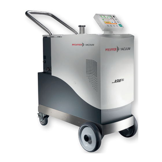
- Page 1 MAINTENANCE INSTRUCTIONS Translation of the original instructions ASM 380 Mobile high performance helium leak detector...
-
Page 2: Table Of Contents
Table of contents Table of contents About this manual ..........4 1.1 Validity. - Page 3 Table of contents 6.1 Shutting down for longer periods ....... 37 6.2 Disposal .
-
Page 4: About This Manual
About this manual Validity This maintenance manual is intended for the customers of the Pfeiffer Vacuum Compa- ny. It describes the product maintenance operations which can be performed by the user on the product concerned. This documentation must be used with the operating manual of the product of the same name. -
Page 5: Conventions
About this manual Conventions 1.2.1 Safety instructions Operating manual safety instructions Pfeiffer Vacuum are based on the UL, CSA, ANSI Z-535, SEMI S2, ISO 3864 and DIN 4844 certification standards. This document de- scribes the following information and danger levels: DANGER Imminent danger Indicates an imminent hazardous situation that will result in death or serious injury. -
Page 6: Pictographs
About this manual 1.2.2 Pictographs Prohibition of an action to avoid any risk of accidents, the disregarding of which may result in serious accidents Warning of a displayed source of danger in connection with operation of the unit or equipment Command to perform an action or task associated with a source of dan- ger, the disregarding of which may result in serious accidents Important information about the product or this document... -
Page 7: Safety And Maintenance Information
Regularly check compliance with all precautionary measures. Do not switch on the product if the covers are not in place. To return the product to one of our Pfeiffer Vacuum service centers, read the after- sales Service procedure and complete the declaration of contamination available on... -
Page 8: Protective Equipment
Safety and maintenance information Use the original packaging to return the product to a Pfeiffer Vacuum service center: the manufacturer shall not be held liable for any damage resulting from transport in unsuitable packaging. Protective equipment In some situations, personal protective equipment must be worn when handling the de- tector and its components. - Page 9 Replacing defective components with parts that are not genuine jeopardizes the prod- uct's initial safety conditions. Use only spare parts available for order from Pfeiffer Vacuum Service. Parts numbers are available in the Spare Parts chapter. To identify the product and communicate with Pfeiffer Vacuum look at the product's nameplate.
-
Page 10: Maintenance Intervals And Responsibilities
Maintenance intervals and responsibilities Maintenance operations for levels 1 and 2 of the interval table are described in this man- ual. Level 3 overhaul operations require a technician from the Pfeiffer Vacuum Service net- work. Component Number of hours in use... -
Page 11: Calibration
Calibration Calibration Purpose Calibration helps ensure that the leak detector is correctly adjusted to detect the tracer gas selected and display the correct leak rate. A calibrated leak is used to calibrate the leak detector. Depending on the test method, different types of calibration can be performed. Test method Hard Vacuum Sniffing... -
Page 12: Calibration With An External Calibrated Leak
Calibration NOTICE Detector calibration When switched on, the detector suggests that the operator carry out an auto-calibration (if calibration parameter = ’operator’). For the optimal use of the detector, this auto-cal- ibration must be performed. In all situations, a manual or automatic calibration must be performed: at least once a day to optimise the measurement reliability for high sensitivity tests... -
Page 13: Calibration Procedure With External Leak In Hard Vacuum Test
Calibration Start a calibration: press the [Auto cal] function key. Fit the sniffer probe (3) in the calibration opening. Tighten the fixing screw (4). Follow the calibration process indicated on the control panel. Loosen the fixing screw (4). Remove the sniffer probe from the calibration opening. Continue the calibration process indicated on the control panel. -
Page 14: Calibration On Concentration
Calibration Calibration on concentration Concentration = container at atmospheric pressure with a gas mixture of a known tracer gas concentration. NOTICE Before launching this function, make sure that the leak detector is in an environ- ment free of tracer gas pollution. 4.4.1 Procedure The calibration on concentration can be made only in sniffing test, detector in Stand-by... - Page 15 Calibration Allocate a [Correction] function key (see Configuration Menu in the Operating Man- ual). Select the 'hard vacuum' or 'sniffing' test mode. If ’Sniffing test’, connect the sniffer probe to the detector: connect it to an external calibrated leak or place it in a container with a known concentration. Press to start a test.
-
Page 16: Maintenance / Replacement
Maintenance / replacement Maintenance / replacement Cleaning Clean the cover(s) with a soft, lint-free cloth and a product that will not damage the painted surfaces or the labels. Covers disassembly For all maintenance operations (apart from handling), immobilise the leak detector by setting the brakes on the rear wheels. - Page 17 Maintenance / replacement Lift the cover vertically by holding it by the black handle on the inside of the casing and the control panel's support arm. Place it in front of the detector in its alignment: check that the control panel cable is clear.
- Page 18 Maintenance / replacement Cover removed: – The operator must never perform mechanical actions to the calibrated leak. – The operator must never move the detector by pulling on the leak. Placement Shut down the detector (Position the circuit breaker on O, control panel switched off and mains power cable disconnected).
- Page 19 Maintenance / replacement Check that the control panel cable is clear: the control panel must be able to move at least 1 m from its support. Remove the two white screw covers (one on each side of the detector) and screw in the two screws that hold the cover in place.
-
Page 20: Disassembly Of The Cap
Maintenance / replacement CAUTION Risk of injury When handling the product, there is a risk of injury due to the back panel not being af- fixed properly. To guarantee proper rear panel mechanical position on the frame: Make sure that the 10 screws are present and screwed in correctly. 5.2.3 Disassembly of the cap Removal... -
Page 21: Maintenance Of The Internal Calibrated Leak
Maintenance / replacement Check cover alignment with the detector cover top: if necessary, move the cover. Incorrect positioning: Correct positioning: gap between the cap and the cover cap and cover aligned Lift the cap up gently: tighten the 4 screws. Shut the cover and check that it has re- mained in a line with detector cover. - Page 22 Maintenance / replacement NOTICE Change the internal calibrated leak if it has significant impact marks. Procedure Keep all of the removed screws for subsequent reassembly of the unit. Remove the cover (see 5.2.1). Disconnect the temperature sensor (3) from the calibrated leak. Never separate the temperature sensor from the calibrated leak.
-
Page 23: Recalibration
However, to guarantee the reliability of the test, we recommend that you regularly reca- librate (2 years maximum) every leak with reservoir to check its leak rate: this applies to both internal and external calibrated leaks. Return the leak to your Pfeiffer Vacuum service center for recalibration purposes. 5.3.3 Setting... -
Page 24: Analyzer Cell Maintenance
Maintenance / replacement F-74000 ANNECY S/N:FC15000123 P/N:119678 1,3E-7 Value..: mbar.l/s ± 10 % 1,3E-8 Pa.m /s ± 10 % Calibration date...: 15-Jan-2015 Lost per year..: 2 % Temperature..: 23°C Temperature coeff: 3 % HELIUM CALIBRATED LEAK Fig. 2: Example of identification label Analyzer cell maintenance NOTICE Cleanliness guarantee... -
Page 25: Seals Replacement
Maintenance / replacement 5.4.2 Seals replacement Check the condition of the seals every time you work on the analyzer cell (filament re- placement for example): change them if necessary. Spare parts 2 seals (see 9) Seal is consumables. As such, it is not covered by the warranty. Procedure Fig. - Page 26 Maintenance / replacement F1 Filament 1 in the menu F2 Filament 2 in the menu Make sure that the filament connectors (6) are perpendicular to the supporting surface and parallel to each other. Fig. 6: Positioning the filament Fit the new filament in its housing against the 2 centring stops (7). Attach it with the ®...
-
Page 27: Pirani Gauge Maintenance
Maintenance / replacement Fig. 7: Fitting of the fastening clip Pirani gauge maintenance The PI3C gauge is a sensor used to obtain a measurement of the pressure measured at the inlet of the DN 40 ISO-KF valve of the detector. This PI3C gauge is a convection Pi- rani gauge. -
Page 28: Gauge Cleaning
Maintenance / replacement NOTICE Problems where the filament shuts off can occur: Test the gauge alone. Wait for a few hours of operation before making a new setting. If the problem persists, clean the analyzer cell or replace the PI3C gauge. As a last resort, perform a helium leak tightness test (inside the detector). -
Page 29: Fan Maintenance
Maintenance / replacement Fan maintenance Tools/Spare 3 mm Allen key supplied in the maintenance kit parts Fan (see 9) Procedure Shut down the detector (Position the circuit breaker on O, control panel switched off and mains power cable disconnected). Remove the cover (see 5.2.1). Unplug the fan's power cable. -
Page 30: Control Panel Maintenance
Maintenance / replacement Shut down the detector (Position the circuit breaker on O, control panel switched off and mains power cable disconnected). Remove the cover (see 5.2.1). Disconnect the purge from the ACP 40 primary pump to vacuum block: – Unlock the purge tube (5) from its connector (4) with 2 fingers. –... -
Page 31: Replacement Of The Arm
Maintenance / replacement Optional: As a precaution, free the cable from control panel if you had wound it around the inlet port. 5.8.2 Replacement of the arm Spare part Arm (see 9) Procedure Shut down the detector (Position the circuit breaker on O, control panel switched off and mains power cable disconnected). -
Page 32: Replacement Of The Control Panel Cable
Maintenance / replacement Push the arm (3) totally in the path and screw the 4 fastening screws (1) on the arm (3) panel support plate (2). 5.8.3 Replacement of the control panel cable Spare part Cable (see 9) Scissors x mm Allen key supplied in the maintenance kit Note: The fixing clamps are not supplied in maintenance part: standard trade parts. - Page 33 Maintenance / replacement Tighten the cable (1) completely during the below operations to maintain a maximum range during control panel use. You must put the ferrite (4) back in place to comply with EMC safety standards. Pass the new control panel cable (1) under the harness and attach it to the cable fixing (5).
-
Page 34: Replacement Of The Vacuum Vessel
Maintenance / replacement 7 cm 3 cm On the supervisor board: – reconnect the harness (2). – screw the cable fixing clamp. Insert the ferrite (4) fixing clamp (3). Tighten the fixing clamp (3) around the ferrite (4) and cut its end. Connect the control panel. -
Page 35: Replacement Of The Wheels
Maintenance / replacement Unscrew the 2 screws (1) of the ATH 184 pump (3) fixing sheet metal (2). Lift the fixing sheet metal (2) and free the vacuum vessel (4). On one side of the vacuum vessel, unscrew the fixing screw (6) of the vacuum vessel plug (4). - Page 36 Maintenance / replacement Access Put the leak detector on blocks placed under the frame (min. height: 20 cm/7.87 inch) to free the wheels. Procedure for the front Unscrew the fastening screw (1) from the hubcap axis (2) of the wheel (3). wheels Remove the hubcap axis (2) and keep it.
-
Page 37: Decommissioning
Operation of the Operating Instructions. If a problem occurs, contact your Pfeiffer Vacuum service center. Disposal WARNING Environmental protection... - Page 38 – EEE is subject to the regulations in force as regards the recycling of end-of-life prod- ucts – complete EEE that has been neither modified nor retrofitted, and has used only spare parts from Pfeiffer Vacuum, including their assemblies and sub-assemblies, but ex- cluding the batteries. Product sold outside...
-
Page 39: Malfunctions
Malfunctions Malfunctions What happens in the event of a defect The leak detector can display warnings or faults on screen at any time Fig. 9: Ecran standard avec avertissement [i Next] 7.1.1 Warning fault display Press the key to display the fault. Level 1: Warning Press the [i Next] key to display the maintenance information Level 2: Major fault: erroneous measurement... - Page 40 Malfunctions Level RS command RS-232 Code Information loss of cal test mode Dynamic calib. failure Sensor Type/Connector w145 maintenance requested w150 primary pump service w160 secondary pump service w180 2A wire change w181 1A wire change w182 No output on wire 2 w183 No output on wire 1 w211...
-
Page 41: Troubleshooting Guide
Malfunctions Troubleshooting guide The troubleshooting guide helps correct the malfunctions reported on the detector's con- trol panel or affecting the detector. It can be consulted from an interactive application specifically developed for the technical documentation. 7.2.1 Installation of the application Insert the Operating manual CDRom into the CD/DVD player of the computer. - Page 42 Malfunctions...
-
Page 43: Service
Fill out the "Service Request/Product Return" form and send it to your local Pfeiffer Vacuum Service contact. Include the confirmation on the service request from Pfeiffer Vacuum with your ship- ment. Fill out the declaration of contamination and include it in the shipment (mandatory!). -
Page 44: Spare Parts
Spare parts Spare parts Ordering information Spare parts available for sales, classified by functions are listed in this chapter. Function See following pages Tool F100 Monitoring and Display F200 Power and electrical supply F300 Automatic control system and electronic circuits F400 Measurement F500... - Page 45 F 100 Tools ASM 380 Description Qty Remarks 110715 A006 DN16KF Calibrated Leak Adaptator Kit 110716 A007 DN25KF Calibrated Leak Adaptator Kit A010 DN16KF Needle Valve A013 Tee, Reducing - DN25/25/16KF 068269 FV4610 A016 Calib. Leak With Valve 1-3.10-6 DN25KF...
- Page 46 F 200 Monitoring and display ASM 380 Description Qty Remarks 113010S B025 3G Control Panel - Service SD card delivered with the panel B026 P0395E1 3G Control Panel Board B028 Cable for Control Panel 3G See sheet E 630 B029...
- Page 47 F 300 Power and electrical supply ASM 380 Description Qty Remarks 118392 C110 Cable, Main Power; 5 m - France/Germany 118393 C111 Cable, Main Power; 52 m - USA C112 Harness; Block - 380 C114 Fan - 380/30 A459286 See sheet E 550...
- Page 48 F 400 Automatic control system and electronic circuits ASM 380 Description Qty Remarks 060097 D026 Loudspeaker; 90 DB/D 10 cm See sheet E 330 D042 P0365E1 Converter Board See sheet E 201 D052 P0401E1 Power Supply Board - 310/380 D054...
- Page 49 F 500 Measurement ASM 380 Description Qty Remarks 076112 E038 Shock Absorber - C E040 Cell, Analyzer ; Packaging E041 Magnet 3 masses - Analysis Cell E047 Filament for 3G Analyzer Cell 114864S See sheet E 430 See sheet E 431 E048 Preamp.
- Page 50 F 600 Pumping ASM 380 Description Qty Remarks 105707 F041 Silencer 58 x 138 mm 066752 F106 Flow Reducer 50 SCCM DN16KF - 380 See sheet E 702 F108 Hose, ACP 40 - 380 A332212 F109 Flange, Blank DN16KF - G 1/8"...
- Page 51 F 600 Pumping ASM 380 Description Qty Remarks F111 ATH 184 - 380 - Service A464294 F114 Black Circular Feed-Through Sleeve - 380 F115 Shock Absorber - C 076112...
- Page 52 F 700 Valves ASM 380 Description Qty Remarks 067040 G001 Minisol Valve Coil 24 V See sheet E 530 G002 Coil 24 V DC 23 W See sheet E 530 G004 Valve Kit, NC Bacosol (104655) 106935 See sheet E 530...
- Page 53 F 700 Valves ASM 380 Description Qty Remarks 101303 G006 Valve + Coil , 2/2NC Bacosol 24V DC/8W See sheet E 530 A464085 G051 Dust-Proof Filter - 380 See sheet E 532 G052 Valve Block - 380 See sheet E 110...
- Page 54 F 800 Pipes - Connections - Seals ASM 380 Description Qty Remarks H001 Tubing, PVC; D 4 x 1 mm A458324 H005 Connector for Plastic Tube 4 x 1 H006 Body Female Connector G 1/8 RBE03.2100 082988 H009 Bellows, SS; DN25/40KF L 250 mm...
- Page 55 F 800 Pipes - Connections - Seals ASM 380 Description Qty Remarks 113058 H152 Body Female Connector 1/8 BSPP 113059 H153 Male Union 6 mm - 1/8 BSPP H154 Blue Tubing, Polyurethane D 6 - Ep 1 mm 118207 Sold to the meter...
- Page 56 F 900 Cover ASM 380 Description Qty Remarks 076192 I020 Lifting Ring M8 118203 I077 Pivoting Caster 4" - 380 See sheet E 650 I078 Fixed Caster 8" - 380 118204 See sheet E 650 I080 Arm - Control Panel Holder - 380...
- Page 57 F 1000 Options and accessories ASM 380 Description Qty Remarks 082152 J075 O'Ring 5.33 x 113,67 NBR 105847 J077 20 μm Poral Filter D 114 mm J120 Bottle-Holder Clamp 5 L. - 380 115319 See sheet B 240 J121 Bottle-Holder Clamp 15 L. - 380...
- Page 58 F 1000 Options and accessories ASM 380 Description Qty Remarks P0482E1 J113 P0482E1 Bluetooth Board See sheet B 240 118088S J115 I/O interface module - 380 See sheet B 300 J116 I/O interface + Wi-Fi module - 380 118089S See sheet B 300...
- Page 59 VACUUM SOLUTIONS FROM A SINGLE SOURCE Pfeiffer Vacuum stands for innovative and custom vacuum solutions worldwide, technological perfection, competent advice and reliable service. COMPLETE RANGE OF PRODUCTS From a single component to complex systems: We are the only supplier of vacuum technology that provides a complete product portfolio.
Need help?
Do you have a question about the ASM 380 and is the answer not in the manual?
Questions and answers
We had to cycle the power on our ASM 380 unit, and when it came back up, it got stuck on the message "Starting Secondary Pump". We powered it down, waited 30minutes, then turned it back on. Then it came up with these two Warning messages: e096: Auto-cal Failure and e058: Sensitivity Too High. What do we do to fix these warnings?
The context provided does not give detailed steps to fix the warnings. However, based on the information:
- For e096: Fault in Autocal +2nd code, it suggests an issue with the automatic calibration process. Actions typically involve:
- Check and clean the internal sensors.
- Verify calibration conditions (temperature, background levels).
- Restart the autocalibration process manually.
- For e058: Sensitivity Too High, it indicates the unit is detecting leaks too sensitively. Actions usually include:
- Inspect and clean the vacuum system and sensors.
- Ensure there are no contaminations or false leak sources.
- Recalibrate the system.
If problems persist, a full maintenance check or contacting technical support is recommended.
This answer is automatically generated