Pfeiffer Vacuum ASI 35 Operating Instructions Manual
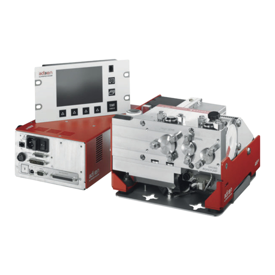
Integrable industrial leak detector
Hide thumbs
Also See for ASI 35:
- Operating instructions manual (154 pages) ,
- Maintenance instruction (40 pages) ,
- Maintenance instructions manual (37 pages)

Subscribe to Our Youtube Channel
Related Manuals for Pfeiffer Vacuum ASI 35


Summary of Contents for Pfeiffer Vacuum ASI 35
- Page 1 OPERATING INSTRUCTIONS Translation of the Original ASI 35 Integrable industrial leak detector...
- Page 2 These operating instructions describe all models and variants of your product. Note that your product may not be equipped with all features described in this document. Pfeiffer Vacuum constantly adapts its products to the latest state of the art without prior notice. Please take into account that online operating instructions can deviate from the printed operating instructions supplied with your product.
-
Page 3: Table Of Contents
Table of contents Table of contents About this manual Validity 1.1.1 Products concerned 1.1.2 Applicable documents Target group Conventions 1.3.1 Pictographs 1.3.2 Instructions in the text 1.3.3 Labels 1.3.4 Abbreviations Safety General safety information 2.1.1 Safety instructions 2.1.2 Precautions Intended use Foreseeable misuse Transportation and Storage Receipt of the product... - Page 4 Table of contents 5.5.2 Setting 5.5.3 Atmospheric pressure/ Limit pressure adjustments Commissioning Start-up of the detector Detector powering off Familiarize yourself with the control panel Operation Use conditions Prerequisites for optimizing use Operation monitoring Test Start/Stop Calibration 7.5.1 Calibration in hard vacuum test mode with internal calibrated leak 7.5.2 Calibration in hard vacuum test mode with external calibrated leak 7.5.3 Calibration in hard vacuum test mode with machine calibration 7.5.4 Calibration in hard vacuum test with a pumping system in parallel...
- Page 5 8.6.8 Input/Output: Serial link 1 and Serial link 2 8.6.9 Input/Output: I/O connector 8.6.10Secondary Pump Speed 8.6.11SD Card menu 8.6.12Service Maintenance/Replacement Service solutions by Pfeiffer Vacuum Accessories Technical data and dimensions 12.1 General 12.2 Technical characteristics 12.3 Units of pressure 12.4 Gas throughputs...
- Page 6 List of tables List of tables Tbl. 1: Units of pressure and their conversion Tbl. 2: Gas throughputs and their conversion Tbl. 3: Default settings: ‘Set Points’ menu Tbl. 4: Default settings: ‘Test’ menu Tbl. 5: Default settings: ‘Spectro’ menu Tbl.
-
Page 7: About This Manual
Keep the manual for future consultation. 1.1 Validity These operating instructions are a customer document of Pfeiffer Vacuum. The operating instructions describe the functions of the named product and provide the most important information for the safe use of the device. The description is written in accordance with the valid directives. The information in these operating instructions refers to the product's current development status. -
Page 8: Instructions In The Text
About this manual Key point on the illustration to be checked Stated tightening torque to be applied 1 2 3 Respect the chronological order of operations and/or assembly/disassembly direction 1.3.2 Instructions in the text Usage instructions in the document follow a general structure that is complete in itself. The required ac- tion is indicated by an individual step or multi-part action steps. - Page 9 About this manual Packaging This label guarantees to the user that the product packaging has not been opened FR AEOF 00165062 - assurance qualité / quality control since leaving the factory. Electronic module For service centers use only Pu_GL : 1 Pu_N : 1 Mu_GL : 12856 Mu_N : 31 Mu_Cal : 1...
-
Page 10: Abbreviations
About this manual Product rating plate. S/N HLDxxxxxx This rating plate can be consulted on the detection module (2 labels: 1 on the 98 avenue de Brogny F-74000 ANNECY Made in France connection port side and 1 on the module frame. P/N : Weight Part Number... -
Page 11: Safety
► Maintain the distances specified by the manufacturer of the pacemakers. – Pfeiffer Vacuum recommends a safety distance of at least 130 mm between the pacemaker and the product. ► Avoid the influence of strong magnetic fields by means of magnetic field shielding. - Page 12 Safety WARNING Electric shock hazard Voltage and current can cause electric shock. Only skilled, authorized people may carry out maintenance work. ► Insulate and lock the power supply circuit by setting the switch to O. ► Disconnect the power supply cable from all power sources before working on the product and/or removing the covers.
-
Page 13: Precautions
Safety 2.1.2 Precautions Duty to provide information on potential dangers The product holder or user is obliged to make all operating personnel aware of dangers posed by this product. Every person who is involved in the installation, operation or maintenance of the product must read, understand and adhere to the safety-related parts of this document. - Page 14 Safety ● pumping of reactive, chemical or toxic fluids, ● pumping of condensable vapors, ● operation in potentially explosive areas, ● product movement as soon as the product is power on, ● use of accessories or spare parts, which are not named in this manual, ●...
-
Page 15: Transportation And Storage
► Wait 5 minutes after power-off before working on the product and/or removing the cover(s). 3.3 Storage Pfeiffer Vacuum recommends storing the products in their original transport packaging. ► Store the electronic module, the vacuum module and the industrial control panel in their original packaging (with the detection module's turbomolecular pump in a vertical position). - Page 16 Transportation and Storage The lever of the manual valve must be removed to transport the detector: the lever kit is supplied with the detector. It is not necessary to refit the lever to remove the blanking plate. 1. Remove the blanking plate with manual valve before using the detector, whatever the installation configuration of the detector in the customer's equipment may be.
-
Page 17: Product Description
Product description 4 Product description 4.1 Product identification To correctly identify the product when communicating with our service center, always have the informa- tion from the product rating plate available (see chapter "Labels"). 4.2 Scope of delivery ● 1 leak detector (1 vacuum module + 1 electronic module) ●... -
Page 18: Electronic Module
Product description Item Designation Analyzer cell Turbomolecular pump decompression knob (for maintenance use only) SplitFlow 50 secondary detection pump Vacuum block Fixing bracket Blanking plate fitted with a manual valve for storage Normal mode detector inlet port: 1 x DN 16 ISO-KF Gross Leak mode detector inlet port: 2 x DN 16 ISO-KF High Sensitivity mode detector inlet port: 1 x DN 16 SO-KF and 1 x DN 25 ISO-KF 4.3.2 Electronic module... -
Page 19: Connection Interface
Product description 4.4 Connection interface START STAND-BY 14-15 A - Industrial control panel Standard remote control connector SD card Buzzer connector 1) Option/accessory (order separately) 2) Accessory (order separately) B - Electronic module Power supply (MAIN POWER) Fuses Mains switch Communication interface according to order configuration (example) 15-pin Sub-D connector for electronic module/vacuum module cable (VACUUM BLOCK) 25-pin Sub-D connector for electronic module/vacuum module cable (ACCESSORIES) Pressure gauge connector (PRESSURE) -
Page 20: Test Methods
Product description C - Vacuum module 15-pin Sub-D connector for electronic module/vacuum module cable (VACUUM BLOCK) 25-pin Sub-D connector for electronic module/vacuum module cable (ACCESSORIES) Standard sniffer probe connector Smart sniffer probe connector 24 V presence indicator LED 2) Accessory (order separately) 4.5 Test methods The test method is chosen depending on the part to be tested. -
Page 21: Control Panel Description
Product description 4.6 Control panel description START STAND-BY Standard remote control connection (accessory). Changing the application screens: return to the home page (“standard” screen) from any menu. Changing the level of function keys. START/STAND-BY button Test Start/Stop. Quick access to functions (see chapter “Function keys”). Displaying a function key level: starting the function or displaying a sub-menu by touching the screen. -
Page 22: Installation
Installation 5 Installation 5.1 Securing the modules Dimensions of the 3 modules: see chapter "Dimensions" The drawings for each module are available on the operating instructions USB. WARNING Risk linked to integration into the customer’s system The product is a fuse detector which can be integrated into the equipment. ►... -
Page 23: Attaching The Electronic Module
Installation NOTICE Risk of product components overheating In cases of poor ventilation, there is a risk of the detector’s internal components deteriorating due to overheating. ► Comply with the permitted ambient operating temperature. ► Leave a free space of 10 cm around the vacuum module. Fixing bracket The drawing of the vacuum module attachment bracket is available on the operating manual USB. - Page 24 Installation 1 Fixing bracket ½ rack module fastening plate ● A plate for mounting the electronic module in a ½ rack space is supplied with the detector (the plate drawing is available on the operating instructions USB). 1 ½ rack plate Precautions to take when you fix the control panel and electronic module in a 1 rack format.
-
Page 25: Attaching The Industrial Control Panel
Installation Attaching the feet to the module 4 rubber feet are screwed onto the electronic module. They allow the module to be positioned on a ta- ble. It is possible to screw these 4 feet on the other sides of the module. 1 Rubber feet (x4) Feet mounting point Ventilation... - Page 26 Installation 1 SD card ½ rack module fastening plate The drawing of a plate used to mount the industrial control panel in a 1 rack format is available in the operating instructions USB (manufacture of this plate is at the customer’s expense). Precautions to take when you fix the control panel and electronic module in a 1 rack format.
-
Page 27: Connecting The Installation To Be Tested
Installation – – Observe +/- polarities when connecting the control panel wiring harness to the buzzer. 1 Harness Buzzer ► To stop the buzzer without disconnecting it, select the “Mute” function using a function key (see chapter “Function keys”). 5.2 Connecting the installation to be tested NOTICE Risk of deterioration of parts or installations There is a risk of deterioration for parts or installations connected to the leak detector vacuum circuit. -
Page 28: Vacuum Circuit Of The Vacuum Module
► Never exceed a load weight of 10 kg on an inlet port. 5.2.3 Vacuum circuit of the vacuum module The customer's system will be connected to the vacuum module on one or more inlet ports. 10+11 Vacuum circuit of the ASI 35 vacuum module Item Designation Analyzer cell... -
Page 29: Connection Of The Primary Pump
High sensitivity mode inlet port - 1 x DN 25 ISO-KF Blanking plate, DN 25 ISO-KF Calibration valve Roughing valve of the internal calibrated leak ASI 35 vacuum module 1) ‘Internal calibration’ option/accessory 5.2.4 Connection of the primary pump Characteristics Primary pump... -
Page 30: Gross Leak Mode Port Connection
Installation Item Designation Primary pump ASI 35 vacuum module 1) ‘Internal calibration’ option/accessory 2) At the customer’s expense 5.2.5 Gross Leak mode port connection Characteristics of this type of connection ● Limited sensitivity ● Very good analyzer cell protection Connection ► See chapter “Installation instructions to be observed”... -
Page 31: Normal Mode Port Connection
Installation Item Designation Customer’s system ASI 35 vacuum module 1) ‘Internal calibration’ option/accessory 2) At the customer’s expense Calibration (the detector to be equipped with the ‘Internal calibration’ option/accessory) ● Test valve 1 is closed throughout the calibration phase. 5.2.6 Normal mode port connection Characteristics of this type of connection ●... -
Page 32: High Sensitivity Mode Port Connection
Designation Roughing valve Pumping system Customer’s system ASI 35 vacuum module 1) ‘Internal calibration’ option/accessory 2) At the customer’s expense Calibration (the detector to be equipped with the ‘Internal calibration’ option/accessory) ● Test valve 2 is closed throughout the calibration phase. -
Page 33: Connection On The Gross Leak, Normal And High Sensitivity Mode Ports
Pumped chamber or part Roughing valve Pumping system Customer’s system ASI 35 vacuum module 1) ‘Internal calibration’ option/accessory 2) At the customer’s expense Calibration (the detector to be equipped with the ‘Internal calibration’ option/accessory) ● Test valve 3 is closed throughout the calibration phase. -
Page 34: Connection In Sniffer Mode
Pumped chamber or part Roughing valve Pumping system Customer’s system ASI 35 vacuum module 1) ‘Internal calibration’ option/accessory 2) At the customer’s expense Calibration (the detector to be equipped with the ‘Internal calibration’ option/accessory) ● Test valves 1, 2 and 3 are closed throughout the calibration phase. -
Page 35: Gauge Connection (Accessory)
Installation NOTICE Risk of deterioration due to overpressure at exhaust Too much pressure at the detector’s exhaust risks damaging the detector. ► Ensure that the customer application exhaust line is always under slightly negative pressure. ► Make sure the detector’s exhaust pressure does not exceed 200 hPa (relative). 5.5 Gauge connection (accessory) ►... -
Page 36: Setting
Pumped chamber or part Roughing valve Pumping system Customer’s system Gauge 37-pin I/O communication interface ASI 35 vacuum module ASI 35 electronic module 1) ‘Internal calibration’ option/accessory 2) At the customer’s expense 3) Option/Accessory 5.5.2 Setting Each one of the 3 adjustable thresholds allows a relay output to be switched. -
Page 37: Atmospheric Pressure/ Limit Pressure Adjustments
Installation Relay activation 5.5.3 Atmospheric pressure/ Limit pressure adjustments ► Refer to instructions delivered with the gauge used. 37/108... -
Page 38: Commissioning
Commissioning 6 Commissioning 6.1 Start-up of the detector 1. Make sure the customer's primary pump is connected to the detector and powered up. 2. Connect the power supply to the mains connector using the power cable supplied with the detec- tor. 3. Position the mains switch to I. 4. -
Page 39: Operation
Operation 7 Operation 7.1 Use conditions WARNING Risk of injury due to the use of hydrogen as tracer gas Hydrogen can be used as a tracer gas for leak detection. Depending on its concentration, in the worst scenario, there may be a risk of explosion. ►... -
Page 40: Test Start/Stop
Operation Type of fault Control panel Warning Display of fault. Click on the pictogram to display the fault. Error Display of fault. Click on the pictogram to display the fault. Critical error Display of the message “Critical error - E244”. Contact our service center. -
Page 41: Calibration
Operation Sniffer test The sniffer test requires the 'Sniffer' option/accessory (see chapter 'Accessories'). 1. Prepare the installation to be tested. 2. Select the ‘sniffer’ test method (see chapter “Test method”). 3. Depending on the model of the detector, select the model of the sniffer probe used (see chapter “Type of probe”). -
Page 42: Calibration In Hard Vacuum Test Mode With Internal Calibrated Leak
Operation The manufacturer does not provide calibrated leaks in He and H The choice of external calibrated leak depends on application requirements: use a calibrat- ed leak from the same leak rate range as the leak to be measured. 7.5.1 Calibration in hard vacuum test mode with internal calibrated leak Calibration with an internal calibrated leak requires the 'Internal calibration' option/accessory (see chap- ter “Accessories”). -
Page 43: Calibration In Hard Vacuum Test With A Pumping System In Parallel
Operation If the detector is equipped with ‘Internal calibration’ option/accessory, you are advised to perform a machine calibration. If the detector is not equipped with the 'Internal calibration' option/accessory, it is advisable to perform an autocorrection (see chapter "Calibration with a pumping system in parallel"). Before performing a machine calibration, the detector should be calibrated by carrying out a calibration with the internal or external calibrated leak. -
Page 44: Calibration In Sniffer Test With External Calibrated Leak
Operation 4. Press the START/STAND-BY button to start a test. 5. Press the [CORRECTION] function key. – if the value of the correction factor to be applied is known: – Press [Value]. – Set the correction factor to be applied. The correction factor is the coefficient to be ap- plied to the measured leak rate. -
Page 45: Calibration In Sniffer Test On Concentration
Operation 8. Follow the instructions given by the leak detector. – Press [Next] to move to the next step. 9. Wait 10 seconds (at least) before reading the leak rate. 7.5.6 Calibration in sniffer test on concentration The sniffer test requires the 'Sniffer' option/accessory (see chapter 'Accessories'). Concentration = volume at atmospheric pressure filled with a gas mixture for which the tracer gas con- tent is known. -
Page 46: Navigation
Operation Example of each application screen “Main” Screen (Standard) Information about the current test “Graph” screen Monitoring and recording the leak rate and/or the inlet pressure “Synoptic” screen Schematic diagram of the detector and the status of the valves “Settings” screen Detector parameters The contents of the screens are provided as an example: depending on the detector settings, the dis- play may be different. -
Page 47: Main Screen (Home)
Operation Access locked: access with password "Pixelated" key: access prohibited for the product xxxxxxxx “Grey” key: access settings or function “White” key: key not customiable, for information “Measurement information” key: to display the measured leak rate Arrows for navigating within the menus Access to the error/warning window Value selected is customizable Keys for setting the values... -
Page 48: Graph Screen
Operation Item Function Detector inlet pressure bargraph display (unit consistent with the leak rate unit) 1 · 10 permanently displayed if there is no pressure gauge connected Leak rate Bargraph display (adjustable scale) (color depends on test results) Digital display of leak rate The color of the screen varies depending on the test result: ●... -
Page 49: Graph Screen: Graph Clearing
Operation Access: Press on the screen to access the graph parameters. Clear Graph To be launched Graph clearing (see chapter “Graph screen: Graph clearing”). View Record To be set Saving and viewing of a recording (see chapters “Graph screen: saving a recording” and “Graph screen: viewing a recording”). Range To be set Configuration of the graph scales... -
Page 50: Graph Screen: Scales
Operation Configuration Press the graph, then [Record], to modify the recording parameters Choice - Setting limit Duration To be set 0.2 s – 30 s Recording duration See details below Capacity Read only Total recording time according to configured recording duration See details below 1) Initial setting: see chapter “Tree diagram of the Settings menu”... -
Page 51: Graph Screen: Saving A Recording
Operation Period of time displayed on the screen Setting the automatic scale Setting the measured leak rate scale Setting the inlet pressure scale Displaying/Hiding the inlet pressure Displaying/Hiding the measured leak rate Activating/Deactivating the automatic scale Access: Press the graph and [Scale] to modify the graph parameters. Choice - Setting limit Display... -
Page 52: Graph Screen: Viewing A Recording
Operation 7.7.9 Graph screen: viewing a recording At any time, a saved file can be viewed or a zoom can be performed on it, without stopping an ongoing recording. 1 Total recording time ► Press the graph and [View Record] to view the recording made since the last recording was de- leted. -
Page 53: 10Settings Screen
Operation 1 Navigation between next/previous recorded points Moment the measurement took place in re- lation to the start of the recording 2 Displaying the tracer gas leak rate (in red) or the Selecting the display of the leak rate or the inlet pressure (in blue) inlet pressure 3 Marker indicating the selected point... -
Page 54: 12'Measurement' Window
Operation Vacuum circuit example Component Description Red valve Valve closed Green valve Valve open Pumps Press the component to display the operating principle. Analyzer cell ► Access the Synoptic screen by pressing repeatedly on the key 7.7.12 ‘Measurement’ window 1. Press the [Measure] key to display the window. 2. -
Page 55: Settings
Settings 8 Settings The Settings screen allows the user to access 6 menus for configuring the product to use specifications. See chapter “Settings Screen”. Functions by menu [SET POINTS] menu ● Audio alarm ● Digital voice ● Pollution function ● Backgnd Max ●... -
Page 56: Set Points Menu
Settings 8.1 Set points menu 8.1.1 Audio alarm and digital voice This menu is used to configure the sound volumes. The audio alarm and the digital voice are not available directly on the detector. Either: ● an audio headphone or loudspeaker must be connected (maximum power: 0.5 W) on the outputs of the 15/37-pin I/O communication interface connector (option/accessory) (refer to the user man- ual for the communication interface) ●... -
Page 57: Background Maximum
Settings ● an audible signal is emitted to indicate that the detector is in 'Standby' mode ● a message (W222) is displayed informing that the 'Pollution' function is activated. Access: Settings Screen + [Setpoints] Menu Choice - Setting limit Pollution To be enabled Enabled Disabled... -
Page 58: Sniffer Reject Point
Settings Set point setting 1 Exponent setting Mantissa tenth setting 2 Mantissa unit setting 8.1.5 Sniffer reject point This menu is used to define the reject point in sniffing. The reject point is the acceptance threshold for tested parts. Access: Settings Screen + Menu [Set Points] [Sniffer Set Point] Choice - Setting limit Reject point To be set... -
Page 59: Other Pressure Set Points
Settings Access: Settings Screen + Menu [Set Points] [Sniffer Set Point] Choice - Setting limit Probe clogged To be set 1 · 10 – 1 · 10 The threshold unit is the unit set for the detector. 1) Initial setting: see chapter “Tree diagram of the Settings menu” Block the end of the sniffer probe from time to time with your finger to check that the leak rate is going down. -
Page 60: Test Menu
Settings 8.2 Test menu 1 Test menu with ‘Hard Vacuum’ test method Test menu with ‘Sniffer’ test method 8.2.1 Test method This menu is used to select a test method. The sniffer test requires the 'Sniffer' option/accessory (order separately: see chapter 'Accessories'). Access: Settings Screen + Menu [Test] Choice - Setting limit Method... -
Page 61: Test Mode
Settings Display The COR indicator light is displayed on the control panel when the correction factor value is not 1. The leak rate displayed takes into account the correction factor applied. Use of the correction factor must not replace calibration. Access: Settings Screen + Menu [Test] Choice - Setting limit HV correction... -
Page 62: Probe Type
Settings For quick access from the main screen, configure a function key to [MODE] (see chapter “Function keys”). By default, the leak detector is set to work in a ‘Hard vacuum’ test method, in the most sen- sitive test mode: this setting meets the majority of users’ needs. 8.2.4 Probe type This menu is used to select the sniffer probe type used in sniffing (see chapter “Accessories”). -
Page 63: Memo Function
Settings Access: Settings Screen + Menu [Test] [Zero Activation] Choice - Setting limit Activation To be selected Operator ● None: ZERO button inactive Automatic ● Operator: user activation by pressing on the [ZERO] function key, depending on configuration (see below: Zero Exit) ●... -
Page 64: Spectro Menu
Settings 8.3 Spectro menu 8.3.1 Tracer gas This menu is used to select the tracer gas. Access: Settings Screen + Menu [Spectro] Choice - Setting limit Tracer gas To be selected Helium 4 The tracer gas is the gas searched for during a test. Helium 3 Hydrogen 1) Initial setting: see chapter “Tree diagram of the Settings menu”... -
Page 65: Filament Parameters
Settings 8.3.2 Filament parameters Access: Settings Screen + Menu [Spectro] Choice - Setting limit Filament selected To be selected Filament in use for the measurement (2 filaments in the analyzer cell). Filament To be selected Status of the filament in use when the detector is on. ●... -
Page 66: Maintenance Menu
Settings Access: Settings Screen + Menu [Spectro] [Calibrated leak] Choice - Setting limit Loss per Year (%) To be set 0 – 99 Set the loss per year for the calibrated leak used for calibration Ref. T. (°C) To be set 0 –... - Page 67 Settings Access: Settings Screen + Menu [Maintenance] [Timers] Choice - Setting limit Detector Read only Detector running time Filament 1 Read only Running time for filament 1 Function to be launched 1. Press [xxx h] to access the reset function. 2.
-
Page 68: Detector Information
Settings Additional information about Secondary Pump 1 Access: [xxxx h/xxxx h] for the ‘Secondary pump 1’ parameter Choice - Setting limit Sec. Pump #1 Read only Percentage of running time of the secondary pump 1 since the last reset compared to the configured running time interval. Timer Read only Running time since the last timer reset... -
Page 69: Event History
Settings Access: Settings Screen + Menu [Maintenance] [Secondary Pump #1] Status Control of the pump by the detector Rotation Pump status: Synchro/Down/Fail/Running/Ram up Speed (rpm) Pump rotation speed (max 900000 rpm) The pumping speed of the secondary pump can be configured (see chapter “Secondary pump speed”). ►... -
Page 70: Calibration History
Settings 8.4.6 Calibration history The calibration history records the last 20 calibrations made. Beyond 20, the oldest recorded calibration will be replaced by the most recent and so on. Access: Settings Screen + Menu [Maintenance] [Calibration History] 1 Exporting the history in .csv format to the SD card Date and time of the calibration 2 Calibration result 8.4.7 Last maintenance... -
Page 71: Function Keys
Settings Access: Settings Screen + Menu [Configuration] [Unit/Date/Language] Choice - Setting limit Time To be set Format: Hour Minute Second (hh:mm:ss) The time is not automatically updated when switching from summ- er time to winter time and vice versa: it must be updated by the user. -
Page 72: Application Windows
Settings 1. Select the ‘Correction’ function using the arrows. 2. Select the [Mode] function key by pressing repeatedly (function key selected if background is white). 3. Validate the selections. ● The function key previously allocated to [Mode] is now assigned to the [Correction] function. 8.5.3 Application windows The user can display/hide one or more screens or change the order in which they scroll in the loop. - Page 73 Settings Access: Access: Settings Screen + Menu [Configuration] [Application windows] Choice - Setting limit Graph To be selected Activate Graph screen display Deactivate To be set – 4 Order in the loop Synoptic To be selected Activate Vacuum circuit display Deactivate To be set –...
-
Page 74: Screen Settings
Settings 1. Press the order number on the screen for the screen to be modified. 2. Press the [+] and [-] to choose the new order number. 3. Press [Valid]. Example 1 ● The Synoptic screen moved from position 3 to 4 in the loop. -
Page 75: Access - Password
Settings 8.5.5 Access – Password This menu is used to manage the access rights to the various menus and/or screens. Regardless of the user level, a password is required to access this menu. The default password is 5555. The password is not saved in the control panel. If the password is lost, it can be retrieved by using the RS-232 serial link: see the RS-232 serial link operating instructions (see chap- ter “Applicable documents”). - Page 76 Settings To access a locked menu, the user is asked to provide the password. ► Press the pictograph to lock the relevant menu (see example 1). ● On the Settings screen, the locked menus are indicated by a pictograph (see example 2). ►...
- Page 77 Settings Restricted access dis- play Medium access display 2 function keys available Full access display Access level change For a user with restricted or medium access. For a user with full access 1. Press and hold the 1. Access: Settings Screen + button until the Settings screen Menu [Configuration] [Access/ is displayed with all of the locked menus.
-
Page 78: Advanced Menu
Settings 8.6 Advanced menu The Advanced menu is reserved for leak detection experts or for a particular product configuration. 8.6.1 Leak Detection: Start Up timer The start-up timer prevents the leak detector from being used for a pre-determined duration after it has been switched on. -
Page 79: Leak Detection: External Gauge
Settings Possible gauges The gauge should be ordered separately. Gauge type Type of gauge set Gauge model Linear gauge Capacitive Linear CMRxxx Piezo Linear APRxxx Logarithmic gauge Pirani TPR/PCR TPRxxx Capacitive Pirani TPR/PCR PCRxxx 8.6.3 Leak Detection: External gauge This function enables the leak detector to be controlled by an external gauge and/or recover the pres- sure of the detector. -
Page 80: Leak Detection: Calibration
By default, internal leak is selected to allow for a rapid calibration of the leak detector. It is also possible to calibrate the leak detector with an external leak (see chapter “Calibration”). The ‘Internal calibration’ is an option/accessory for the ASI 35. ● Detector not equipped with ‘Internal Calibration’... -
Page 81: Leak Detection: Analyzer Cell
Settings At any time, the user can start a calibration check: with the leak detector in ‘Stand-by’ mode, press the [AUTOCAL] function key twice within 5 seconds. The calibration check enables the operator to save up to 50% time compared to an internal calibration. The calibration check does not modify any calibration parameters. - Page 82 Settings This function provides an adjustment and should not be confused with the correction coeffi- cient. This coefficient complements the correction coefficient. Access: Settings Screen + Menu [Advanced] [Leak detection] [Dy- Choice - Setting lim- namic calibration] Active To be enabled Value To be set 1 ·...
-
Page 83: Leak Detection: Signal Processing
Settings Setting procedure for several tests Several tests can be run to calculate the dynamic calibration coefficient. This allows the coefficient val- ue to be fine-tuned. 1. Implement the preliminary conditions. 2. Activate the dynamic calibration coefficient calculation. 3. Start the 1 test. -
Page 84: Input/Output: I/O Connector
Settings Access: Settings Screen + Menu [Advanced] [Input/Output] then [Serial Choice - Setting limit link 1] or [Serial link 2] Type To be selected Serial Type of connection Refer to the operating instructions for the option/accessory Network 3) 4) used. Not used Parameters Mode... -
Page 85: 11Sd Card Menu
Settings Access: Settings Screen + Menu [Advanced] [Secondary pump speed] Choice - Setting limit Current (rpm/Hz) Read only Current pumping speed of the turbomolecular pump Target (rpm/Hz) To be set 1000 Pumping speed of the turbomolecular pump: 1500 ● 1500 Hz/90,000 min : standard configuration for use of 60,000 the detector within the standard temperature range... -
Page 86: Maintenance/Replacement
Maintenance/Replacement 9 Maintenance/Replacement Maintenance intervals and responsibilities The detector maintenance operations are described in the Maintenance instructions for the detector. The manual specifies: ● maintenance intervals, ● maintenance instructions, ● shutting the product down, ● tools and spare parts. 86/108... -
Page 87: Service Solutions By Pfeiffer Vacuum
We are always focused on perfecting our core competence – servicing of vacuum components. Once you have purchased a product from Pfeiffer Vacuum, our service is far from over. This is often exactly where service begins. Obviously, in proven Pfeiffer Vacuum quality. - Page 88 Service solutions by Pfeiffer Vacuum 5. Prepare the product for transport in accordance with the provisions in the contamination declaration. a) Neutralize the product with nitrogen or dry air. b) Seal all openings with blind flanges, so that they are airtight.
-
Page 89: Accessories
Accessories 11 Accessories Designation Part Number Standard sniffer probe Refer to Pfeiffer Vacuum catalogue Standard sniffer probe extension (10 m) 090216 Remote control RC 10 124193 Smart Sniffer Probe (3 m) BG 449 207 -T Smart Sniffer Probe (5 m) BG 449 208 -T... -
Page 90: Technical Data And Dimensions
Technical data and dimensions 12 Technical data and dimensions 12.1 General Databases of technical characteristics of Pfeiffer Vacuum leak detectors: ● Technical characteristics according to: ─ AVS 2.3: Procedure for calibrating gas analyzers of the mass spectrometer type ─ EN 1518: Non-destructive testing. Leak testing. Characterization of mass spectrometer leak detectors ─... -
Page 91: Units Of Pressure
Technical data and dimensions Secondary pump Minimum detectable leak rate for He with Maximum flow with speed RVP 2005 Smart probe (sccm) Pa m /s (mbar l/s) 1500 Hz 1.5 · 10 (1.5 · 10 1000 Hz 1 · 10 (1 ·... -
Page 92: Dimensions
Technical data and dimensions 12.5 Dimensions Detection module (mm) Electronic module (mm) 1 Removable feet (see chapter Removable fixing brackets, not mounted but delivered with “Attachment of the electronic the detector (see chapter "Attachment of the electronic mod- module”) ule") Industrial control panel (mm) (option/accessory) 1 The cable is not included with the industrial control panel (accessory) 92/108... -
Page 93: Annex
13.1 ASI 20 MD / ASI 30 / ASI35 specific features Electronic module ASI 20 MD ASI 30 ASI 35 1 low voltage module and 1 high volt- 1 multi-voltage single module age module Front side with 1 rack 19" format A plate used to mount the electronic module in a ½... -
Page 94: Tree Diagram Of The Settings Menu
2) ) 1) Accessory 2) Option 3) ASI 35 V2 only 13.2 Tree diagram of the Settings menu Next tables indicate the default settings for the leak detector. When the leak detector is switched off, values and parameters are saved for the next start-up. - Page 95 Annex Access: Settings Screen + Menu [Set Points] Choice - Setting limit Hard Vacuum Set Point Reject point 1 · 10 – 1 · 10 -07 1) 1 · 10 Set point 2 1 · 10 – 1 · 10 1 ·...
- Page 96 Annex Access: Settings Screen + Menu [Test] Choice - Setting limit Cycle end Cycle end Operator Automatic Setting Rough. timer Status Enabled (If automatic) Disabled (If ‘Hard vacuum’ test Setting (If en- 0 – 1 hr method) abled) 10 s Test timer 0 –...
- Page 97 Annex Access: Settings Screen + Menu [Spectro] Choice - Setting limit Calibrated leak Tracer Gas Helium 4 Helium 3 Hydrogen Type If ‘Hard vacuum’ test Without ‘Internal calibra- External method tion’ option/accessory With ‘Internal calibration’ Internal option/accessory External Machine If ‘Sniffer’ test method Sniffer Ext.
- Page 98 Annex Default settings: ‘Maintenance’ menu Access: Settings Screen + Menu [Maintenance] Choice - Setting limit Detector 1) 2) Timers Detector 1) 2) Filament 1 Timer (h) 1) 2) Reset timer Function launching Filament 2 Timer (h) 1) 2) Reset timer Function launching Calibrated Leak Cycles...
- Page 99 Annex Default settings: ‘Configuration’ menu Access: Settings Screen + Menu [Configuration] Choice - Setting limit Unit/Date/ Unit Language mbar · l/s Pa · m Torr · l/s mTorr · l/s atm · cc/s sccm sccs Date Format: Month Day Year (mm/dd/yyyy) Time Format: Hour Minute Second (hh:mm:ss)
- Page 100 Annex Access: Settings Screen + Menu [Configuration] Choice - Setting limit Application win- Standard Window Leak Rate Bar- Zoom on Set dows Parameters graph Point (main screen) Low decade 1 · 10 – 1 · 10 1 · 10 -12 1) High decade 1 ·...
- Page 101 Annex Access: Settings Screen + Menu [Configuration] Choice - Setting limit Access/Password Password 0 – 9999 5555 Set points menu access Lock Unlock Test menu access Lock Unlock Spectro menu access Lock Unlock Maintenance menu access Lock Unlock Configuration menu access Lock Unlock Advanced menu access...
- Page 102 Annex Default settings: ‘Advanced’ menu Access: Settings Screen + Menu [Advanced] Choice - Set- ting limit Leak detection Start-up timer 0 – 1 hr 1 mn 30 s Detector Gauge TPR/PCR pressure Linear gauge Position Standard Full scale (mbar) (if “linear”) 0.1 –...
- Page 103 Annex Access: Settings Screen + Menu [Advanced] Choice - Set- ting limit Leak detection Dynamic cali- Active bration Value (if active) 1 · 10 1 · 10 1 · 10 -7 1) Coefficient (if active) Signal proc- Level Stable essing Stable+ Fast Input/Output...
- Page 104 Annex Access: Settings Screen + Menu [Advanced] Choice - Set- ting limit Input/Output I/O connector Digital Relay 5 - 24 Allocation 5) 6) Output (37-pin I/O depend- 4 - 23 Activation 5) 6) ing on option/acces- 3 - 22 sory) 2 - 21 1 - 20 Select Default...
- Page 105 Annex Access: Press the graph Choice - Setting limit Enable record Enabled Disabled Sampling rate 100 ms – 30 s (if ‘Enable record’ is enabled) 500 ms Clear recording Function launching (if ‘Enable record’ is ena- bled) View record Function launching (if ‘Enable record’...
-
Page 106: Ec Declaration Of Conformity
This declaration of conformity has been issued under the sole responsibility of the manufac- turer. Declaration for product(s) of the type: Leak detector ASI 35 We hereby declare that the listed product satisfies all relevant provisions of the following European Directives. Machinery 2006/42/EC (Annex II, no. 1 A) -
Page 107: Declaration Of Conformity
EN 60204-1: 2006 ENV 50204: 1996 The manufacturer's authorized representative in the United Kingdom and the authorized agent for compiling the technical documentation is Pfeiffer Vacuum Ltd, 16 Plover Close, In- terchange Park, MK169PS Newport Pagnell. Signature: Pfeiffer Vacuum SAS...
Need help?
Do you have a question about the ASI 35 and is the answer not in the manual?
Questions and answers