Pfeiffer Vacuum ASI 35 Operating Instructions Manual
Modular leak detector
Hide thumbs
Also See for ASI 35:
- Operating instructions manual (154 pages) ,
- Maintenance instruction (40 pages) ,
- Maintenance instructions manual (37 pages)

Related Manuals for Pfeiffer Vacuum ASI 35


Summary of Contents for Pfeiffer Vacuum ASI 35
- Page 1 OPERATING INSTRUCTIONS Translation of the original instructions ASI 35 Modular leak detector...
-
Page 2: Table Of Contents
Table of contents Table of contents About this manual ..........5 1.1 Validity. - Page 3 Table of contents 6.1.7 "Vacuum circuit" screen ....... . 34 6.1.8 "Measurement"...
- Page 4 Appendix ........... . . 83 12.1 ASI 20 MD / ASI 30 / ASI 35 specific features ..... 83...
-
Page 5: About This Manual
About this manual Validity This operating manual is for customers of Pfeiffer Vacuum. It describes the functioning of the designated product and provides the most important information for safe use of the unit. The description follows applicable EU guidelines. All information provided in this operating manual refers to the current state of the product's development. -
Page 6: Conventions
About this manual Conventions 1.2.1 Safety instructions Operating manual safety instructions Pfeiffer Vacuum are based on the UL, CSA, ANSI Z-535, SEMI S2, ISO 3864 and DIN 4844 certification standards. This document de- scribes the following information and danger levels: DANGER Imminent danger Indicates an imminent hazardous situation that will result in death or serious injury. -
Page 7: Pictographs
About this manual 1.2.2 Pictographs Prohibition of an action to avoid any risk of accidents, the disregarding of which may result in serious accidents Warning of a displayed source of danger in connection with operation of the unit or equipment Command to perform an action or task associated with a source of dan- ger, the disregarding of which may result in serious accidents 1.2.3... - Page 8 About this manual Indicates if the Ethernet option is installed on the HLD1302577 - RS232 product and its MAC address. MAC address XXXXXX / None Network MAC address xx:xx:xx:xx:xx:xx / None For service centers use only. Pu_GL : 1 Pu_N : 1 Mu_GL : 12856 Mu_N : 31 Mu_Cal : 1 Mu_LDS : 1800...
-
Page 9: Safety
Safety Safety Safety precautions Obligation to inform Any person responsible for installing, using or maintaining the product must first read the security instructions in this operating manual and comply with them. It is the operating customer’s responsibility to protect all operators against the dan- gers associated with the product, with the media pumped and with the entire instal- lation. -
Page 10: Protective Equipment
Safety WARNING Risk associated with process gases A leak detection operation must be carried out under environmental conditions that do not present any risks to the operator and the equipment. The user and/or integrator of the product are fully responsible for the operational safety conditions of the equipment. Therefore the user of the detector must: not test parts or equipment with traces of harsh, chemical, corrosive, inflammable, re- active, toxic, or explosive substances, nor condensable vapours even in small... -
Page 11: Proper Use
Safety Proper use NOTICE EC conformity The manufacturer's declaration of conformity becomes invalid if the operator modifies the original product or installs additional components. Following installation into a plant and before commissioning, the operator must check the entire system for compliance with the valid EU directives and reassess it accord- ingly. -
Page 12: Transport And Storage
Transport and storage Transport and storage Upon delivery, check that the product has not been damaged during transport. If the product is damaged, take the necessary measures with the carrier and notify the manu- facturer. In all situations we recommend: Keeping the product in its original packaging so it stays as clean as it was when dis- patched by us. - Page 13 Transport and storage ● The blanking flange/valve assembly (1) must be removed before using the detector, whatever the installation configuration of the detector in the customer's equipment may be. Keep it in order to re-use it subsequently when transporting the detec- tor or storing it for an extended period.
-
Page 14: Product Description
Product description Product description Product identification To correctly identify the product when communicating with Pfeiffer Vacuum, always have the information from the rating plate available. This nameplate can be consulted on the detection module (2 labels: 1 on the connection port side and 1 on the module frame). -
Page 15: Detection Module
Product description ● The detection module and the electronic module are connected by 2 cables, length 1.5 m/3.5 m/5 m or 10 m according to the selected option. ● The electronic module and the industrial control panel (option/accessory) are connect- ed by one cable, length 1.8 m/5 m or 10 m according to the selected option. -
Page 16: Interface Connection
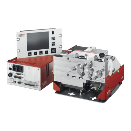
Product description Interface connection START STAND-BY INPUTS/OUTPUTS SERIAL PROFINET INPUTS/OUTPUTS SERIAL PROFIBUS DP-V1 Fig. 2: Human-machine interface Industrial control panel Standard remote control connector SD card Buzzer connector (at the customer's ex- pense) Electronic module Detector ON indicator LED USB connector (USB) Industrial control panel connector (see Ethernet connector (NETWORK) Maintenance instructions) (CONTROL... -
Page 17: Test Methods
Product description Fig. 2: Human-machine interface Electronic module/vacuum block 25-pin Standard sniffer probe connection D-Sub connector 24V presence indicator LED Smart sniffer probe connection Accessory or option (at the customer's expense) Accessory (at the customer's expense) If 37-pin I/O option (at the customer's expense) If Profinet option (at the customer's expense) If Profibus option (at the customer's expense) Test methods... -
Page 18: Installation
Installation Installation Securing the modules Dimensions of the 3 modules (see 11.3). The drawings for each module drawings are available on the operating instructions CD- ROM. WARNING Risk linked to integration in the equipment The product is detector which can be integrated into equipment. It must be integrated into other equipment. -
Page 19: Electronic Module
Installation NOTICE Detector ventilation If there is insufficient ventilation, overheating could cause damage to the components: Comply with the ambient operating temperature. Leave a free space of 10 cm around each side of the detection module. Fixing bracket ● Mounting with M8 CHc screws and Ø 8 mm washers Fig. - Page 20 Installation Fig. 5: Fitting of the mounting lugs ● A plate for mounting the electronic module in a ½ rack space is supplied with the de- tector (the plate drawing is available on the operating instructions CD-ROM). Fig. 6: Electronic module with ½ rack plate Precautions to take when you fix the control panel and electronic module in a 1 rack for- mat: Correct: the electronic module and industrial control panel must be attached separately in the cus-...
-
Page 21: Industrial Control Panel
Installation Feet 4 rubber feet are screwed on the electronic module. They allow the module to be posi- tioned on a table. It is possible to screw these 4 feet on the other sides of the module. Fig. 8: Feet mounting points Ventilation The electronic module is fitted with an internal fan associated with a protection filter on the outside. -
Page 22: Connecting The Part/Installation To Be Tested
Installation To remove/insert the SD card, use a thin non-metallic object. Attachment The drawing of another plate, allowing the electronic module to be mounted in a 1 rack format, is available on the operating instructions CD-ROM (manufacture of this plate at the customer’s expense). -
Page 23: Prerequisites For Optimising Measurement
Installation ASI 35 8+18 7+17 6+17 5+17 5+17 Fig. 10: ASI 35 detection module vacuum circuit Analyzer cell 17 DN 16 ISO-KF blanking flange Internal calibrated leak 18 DN 25 ISO-KF blanking flange Splitflow 50 turbomolecular detection pump Calibration valve... -
Page 24: Gross Leak Mode Port Connection
Gross Leak Mode port connection ● Installation instructions to be observed (see 5.2.3). ● Technical characteristics (see 11.2). ● Limited sensitivity. ● Very good analyser cell protection. ASI 35 8+18 7+17 6+17 Fig. 11: Gross Leak mode connection vacuum circuit... -
Page 25: High Sensitivity Mode Port Connection
Installation ASI 35 8+18 7+17 5+17 Fig. 12: Normal mode connection vacuum circuit DN 16 ISO-KF detector inlet port - Normal 14 Roughing valve mode 10 Customer's installation 15 Test valve 2 (Normal mode) 11 Pumped chamber or part 16 Primary pump (at the customer’s expense) 12 Pumping system ●... -
Page 26: Ports
● Technical characteristics (see 11.2). ● Connecting the customer's installation simultaneously on an inlet port for each mode allows the customer to work in the 3 test modes. ASI 35 7+17 Fig. 14: Gross Leak, Normal and High Sensitivity mode connection vacuum circuit... -
Page 27: Connection To The Mains Power Supply
Installation Connection to the mains power supply WARNING Risk of electromagnetic disturbance The product’s EMC behavior is guaranteed only if the relevant EMC standards are fol- lowed during installation. Use shielded cables and connections for the interfaces in interference-prone environ- ments. -
Page 28: Setting
Installation Fig. 15: Gauge connection Customer installation Chamber or part to be tested Gauge Pumping system Roughing valve (V PREV Test valve 1 (V TEST1 Test valve 2 (V TEST2 Test valve 3 (V TEST3 Primary pumping 10 Vacuum module 11 Electronic module 12 I/O 37-pin option 5.5.2... -
Page 29: Operating For The First Time
Installation Fig. 16: Relay activation 5.5.3 Atmospheric pressure/ Limit pressure adjustments Refer to instructions delivered with the gauge used. Operating for the first time Make sure the customer's primary pump is connected to the detector and powered up. Attach the electrical network to the connector using the power cable delivered with the detector. -
Page 30: Operation
Operation Operation Control panel Industrial control panel with ½ rack format is available as option or accessory. It is interfaced with the detector and is used to: – display information about the test – access the available functions – setting of the detector's parameters. For a screenshot, set a function key to [Screen Copy] (see 7.7.2). -
Page 31: Contrast - Brightness - Screen Saver
Operation Arrows for navigating within the menus Access to the error/warning window Value selected is customisable Keys for setting the values Moving to the next function/screen/parameter Return to the previous display Return to the previous display and confirm the changes made Return to the previous display without confirming the changes made Deleting the selected file Set point setting... -
Page 32: Application Screens
Operation 6.1.3 Application screens The content of the screens is given as an example. Depending on the leak detector and parameters, the display may be different. Fig. 18: Example of each screen 1 "Standard" screen (home) Information about the current test 2 "Graph"... -
Page 33: Standard" Screen
Operation 6.1.4 "Standard" screen Information about the test: display most often shown during a test. Digital display of the leak rate (green ≤ reject set point < red) Bargraph display of the leak rate (adjustable scale) Detector status and Detection mode Access error information Mute function indicator Air inlet function indicator (except ASI 30/35) -
Page 34: Graph" Screen
Operation 6.1.6 "Graph" screen Monitoring and recording the leak rate and/or the inlet pressure. 1 Deleting/Viewing/Recording a plot 2 Plot of the tracer gas leak rate (in red) 3 Scale of the tracer gas leak rate (in red) 4 Time scale 5 Inlet pressure scale (in blue) 6 Inlet pressure plot (in blue) 7 Displaying/Hiding the Measurement window (see 6.1.8) - Page 35 Operation 6.1.9 Function keys The function keys are used to activate/stop a function or to set set points (see 7.7.2). Thanks to the function keys, it is possible to give the operator access to a limited number of functions. Prerequisites to use The leak detector is set to perform a hard vacuum test in the most sensitive test mode according to the initial settings (see 7.2.1).
- Page 36 Operation Set the reject set point if necessary (see 7.3.4). Start a test by pressing The various test stages are displayed. When the detector has reached the most sensitive test mode, wait for the measure- ment to stabilise: the measurement displayed corresponds to the measured leak rate. Stop the test by pressing The test can also be started using a remote control (accessory): see Remote con- trol Operating instructions.
- Page 37 All the detector's parameters are downloaded except the following, which must be set by the operator: – language – serial link (except ASM 310) – time and date – temperature unit (except ASI 35) – pressure unit. Calibration 6.7.1 Purpose Calibration helps ensure that the leak detector is correctly adjusted to detect the tracer gas selected and display the correct leak rate.
- Page 38 Operation Check the following parameters (correct if necessary): ● test method = hard vacuum (see Test Menu) ● type of calibrated leak = internal (see Spectro Menu) ● calibration = operator (see Advanced Menu) Check the leak settings (corrected leak rate to take temperature and time into account if necessary) (see Spectro Menu in the operating instructions).
- Page 39 Operation If the detector is equipped with internal Calibration, you are advised to perform a machine calibration (see 6.7.5). If the detector is not equipped with internal Calibration, you are advised to per- form an autocorrection (see 6.7.6). Machine calibration is advised if the leak detector is connected to an installation equipped with its own pumping system.
- Page 40 Operation ● If ’Sniffing test’, connect the sniffer probe to the detector: connect it to an external calibrated leak (see 6.7.4) or place it in a container with a known concentration. Press to start a test. Press the [Correction] function key. ●...
- Page 41 Operation Fig. 22: Adaptor installation Calibration on concen- Calibration on concentration can only be carried out in sniffing test mode, with the detec- tration tor in Stand-by or test mode. Concentration = container at atmospheric pressure filled with a gas mixture for which the tracer gas content is known.
- Page 42 Advanced settings Advanced settings "Graph" screen Access the "Graph" screen by pressing 7.1.1 Description Monitoring and recording the leak rate and/or the inlet pressure. Fig. 23: "Graph" screen 1 Deleting/Viewing/Recording a plot 2 Plot of the tracer gas leak rate (in red) 3 Scale of the tracer gas leak rate (in red) 4 Time scale 5 Inlet pressure scale (in blue)
- Page 43 Advanced settings ● automatic scale 2 decades: scale from 1·10 to 1·10 Pa·m (1·10 to 1·10 mbar·l/s) ● automatic scale 4 decades: scale from 1·10 to 1·10 Pa·m (1·10 to 1·10 mbar·l/s) Recording Press [Recording]. Duration Recording duration Capacity Total recording time according to recording duration Duration Maximum capacity File size...
- Page 44 Advanced settings 7.1.4 Graph clearing Current window Display the "Graph" screen (see 7.1.1). Press [Clear] (1) and validate the message. Clearing the current window does not delete the current recording or recordings already made. Recording Display the "Graph" screen (see 7.1.1). Press [View Rec.] (1).
- Page 45 Advanced settings Fig. 27: Return to the original graph Measurement Exact measurement of a point only available on a recording. Select the point to measure (2). Fig. 28: Example of the recording of a point 1 Modifying the leak rate and inlet pressure scales 2 Point selected Press [Measure]: the exact measurement of the selected point is displayed.
- Page 46 Advanced settings 7.1.6 Saving a recording This function is used to save the most recent recording on a SD card to be played back/ analysed later on a PC. Saving is not automatic. It is possible to save a screenshot of the recording (.bmp) or to generate a file (.txt) with all the measurements taken.
- Page 47 Advanced settings 7.2.1 Tree diagram of the "Settings" menus The following table shows the detector's initial settings. When the detector is off, values and parameters are saved for the next use. The operator can save and download different leak detector configurations (see 7.8.13). SET POINTS Selection Choice - Setting...
- Page 48 Advanced settings SPECTRO Selection Choice - Setting Initial settings limit Tracer Gas Helium 4 / Helium 4 Helium 3 / Hydrogen Filament Selected 1 / 2 Filament Off / On Filament Status 0 - 100 % 100 % Calibrated leak Tracer Gas Helium 4 / Helium 4...
- Page 49 Advanced settings MAINTENANCE Selection Choice - Setting Initial settings limit Events History Empty Calibration History Empty Last maintenance Maintenance work 1 Date Nbr hours Inspected by Maintenance work 2 Date Nbr hours Inspected by Maintenance work 3 Date Nbr hours Inspected by CONFIGURATION Selection...
- Page 50 Advanced settings CONFIGURATION Selection Choice - Setting Initial settings limit Screen Settings Brightness High / Low High Contrast 0 - 100 Panel off None / None 15 min / 30 min / 1 h / 2 h / 4 hours Paging Function Without RC 500 WL remote control detected - None...
- Page 51 Advanced settings ADVANCED Selection Choice - Setting Initial settings limit Leak Detection Start-up timer 0 - 1 h 1 mn 30 s Detector pressure Gauge TPR / PCR / TPR / PCR gauge LINEAR Position Standard Standard Full scale (mbar) (if Linear) 0.1 - 50000 1000 External gauge...
- Page 52 Advanced settings ADVANCED Selection Choice - Setting Initial settings limit Input/Output Serial Link 1 Type Serial Serial (I/O 15 pins if Profibus Parameters Mode Basic / Advanced / Profinet) Spreadsheet / Advanced / Data export / RC 500 WL / RC 500 / External module / HLT 5XX /...
- Page 53 Advanced settings ADVANCED Selection Choice - Setting Initial settings limit Input/Output Serial Link 2 Type Not used / (I/O 37 pins if option) USB / Network Parameters Mode Basic / Advanced Spreadsheet / Advanced / Data export Handshake None / None XON / XOFF I/O connector...
- Page 54 Advanced settings ADVANCED Selection Choice - Setting Initial settings limit Input/Output I/O connector Digital Transis- 9 - 28 Allocation See Manual I/O 37 Detector Ready tor Output pins (I/O 37 pins if option) Activation NO / NC 8 - 27 Allocation See Manual I/O 37 Reject point pins...
- Page 55 Advanced settings – an audio headphone or loudspeaker must be connected (maximum power: 0.5 W) to the 15/37-pin connector outputs (see 15- or 37-pin I/O board operating instruc- tions). – or a buzzer must be connected to the control panel (see 5.1.3). Audio headphone, loudspeaker or buzzer at the customer's expense.
- Page 56 Advanced settings 7.3.4 Hard Vacuum reject point The hard vacuum reject point defines the acceptance set point for parts that are "accept- ed/rejected" in a hard vacuum test: – Measured leak rate ≤ reject set point: part accepted – Measured leak rate > reject set point: part rejected From the "Settings"...
- Page 57 Advanced settings From the "Settings" screen, press [Set Points] [Additional Pressure Set Point]. Pressure Set Adjust the set point value. Point # “Test” Menu From the "Settings" screen, press [Test]. 7.4.1 Test methods There are 2 possible test methods (see 4.4): ●...
- Page 58 Advanced settings Fig. 34: "Correction" screen using a function key Depending on the concentration of tracer gas used for detecting leaks, the leak rate displayed changes. E.g. the leak rate displayed with a calibrated leak of 1·10 mbar·l/s (1·10 Pa·m /s) (with 100 % He) connected to the detector's inlet.
- Page 59 Advanced settings From the "Settings" screen, press [Test] [Cycle End]. Measurement Setting required if ’automatic’ is set. time Set the measurement duration. When the duration expires, test mode is exited and the measured leak rate is dis- played. Function to be used to automate a small production. 7.4.5 Memo function At the test stop, this function freezes the "Standard"...
- Page 60 Advanced settings 7.5.1 Tracer gas The tracer gas is the gas searched for during a test. 3 gases are available: He and H From the "Settings" screen, press [Spectro]. Tracer gas Select the tracer gas used. The reject set point is memorized for each configurable tracer gas. Calibration The leak detector should be calibrated with a calibrated leak of the same type as the trac- er gas used.
- Page 61 Advanced settings From the "Settings" screen, press [Spectro][Calibrated leak]. Type Define the type of calibrated leak used for calibration. • internal = calibration from the leak detector internal calibrated leak ( He leak only). • external = calibration from an external calibrated leak ( He or H leak).
- Page 62 Set the value for the counter. When the set value is reached, an information message is displayed. Reset Counter Press [Counter reset] to reset the counter. Secondary pump 1: MDP 5011 (ASI 30) - SplitFlow 50 (ASI 35) 7.6.3 Detector Information Fig. 38: Detector Information...
- Page 63 Advanced settings 7.6.5 Event history Event history records the last 30 events. Beyond 30, the oldest recorded event will be replaced by the most recent, and so on. From the "Settings" screen, press [Maintenance] [Event History]. Exporting the history in .csv format to the SD card RS code for the event Date - Time of the event Description of the event...
- Page 64 Advanced settings 7.6.7 Last maintenance This function displays the last three maintenance operations performed on the detector and recorded by the technician having made the intervention. Use the scroll bar to display the last 3 recorded interventions. From the "Settings" screen, press [Maintenance]. [Last maintenance]. Date Date of the maintenance intervention Nbr hours...
- Page 65 Advanced settings Thanks to the function keys, it is possible to give the operator access to a limited number of functions and to use a password to lock unauthorised functions on the "Settings" menu. They are sufficient to manage the detector. To allow the operator to use only the [Start/Stand-by] key, do not allocate a function to the function keys and lock the "Settings"...
- Page 66 Advanced settings 7.7.3 Application screens From the "Settings" screen, press [Config.] [Application Windows]. By pressing repeatedly on the key , the various screens available appear (see 6.1.3). The operator can hide one or more screen or switch the order in which they appear. The "Standard"...
- Page 67 Advanced settings Setting the "Standard" screen From the "Settings" screen, press [Config.] [Application screens] [Std. Screen setting]. Std-By value Display/Hide the leak rate display in Stand-by mode. Inlet Pressure Display/Hide the inlet pressure display. Cell pressure. Display/Hide the cell pressure display. From the "Settings"...
- Page 68 Advanced settings Fig. 48: Locked menus Change password From the "Settings" screen, press [Config.] [Access/Password]. Enter the password (’5555’ by default) and validate. Press [Change Password]. Enter the new password and validate. The password is saved in the control panel. If the password is forgotten, it can be found using the RS-232: see the RS-232 operating instructions.
- Page 69 Advanced settings Limits with Medium access ● Key invalid: no settings can be made without password. ● 2 function keys available: [Basic Param.] and [Info]. ● Function keys hidden. ● Inlet pressure and cell pressure hidden. ● Key valid. ● Measured leak rate and reject set point displayed only in test. Fig.
- Page 70 Advanced settings Enter the current password ('5555' by default) and validate. Press [User Level]. Change the access level: see below the limits for each level. Operator with Full access changing the access level. From the "Settings" screen, press [Config.] [Access/Password]. Enter the current password ('5555' by default) and validate.
- Page 71 Advanced settings Setting From the "Settings" screen, press [Advanced] [Leak Detection] [Detector pressure gauge]. Gauge No automatic recognition of the gauge upon connection. Select the type of external gauge. Full scale (mbar) Only for a linear gauge Set the operating range for the gauge: value indicated on the gauge. ●...
- Page 72 Advanced settings Possible gauges ● The gauge and the cable are at the customer’s expense. ● 2 cables available as accessories (see 10). Type of gauge detected by Gauge model the detector Linear gauges Capacitive Linear CMRxxx Piezo Linear APRxxx Logarithmic gauges Pirani TPR/PCR...
- Page 73 Advanced settings – The detector can be calibrated with an external calibrated leak. – By default, calibration is set to 'Operator' and 'External' leak is selected. ● Detector with Calibration – By default, calibration is set to 'Operator' and 'Internal' leak is selected. Calibration = 'operator’...
- Page 74 Advanced settings Preliminary conditions Perform leak detector autocalibration. Activate the correction factor (see 7.4.2) and set it. Activate the dynamic calibration. Set the target value. Allocate the logic inputs (see 37-pin I/O Operating instructions) or connect the RS- 232 link. Logic input RS-232 command Start/Stop dynamic calibration coefficient calculation...
- Page 75 Advanced settings Coef 1 + Coef 2 + etc. + Coef n coefficient = --------------------------------------- Stop the dynamic calibration coefficient calculation. NOTICE As long as the calculation of the calibration coefficient is not stopped, the coeffi- cient will be adjusted after each test. 7.8.8 Signal processing This function is used to modify signal processing to improve:...
- Page 76 Use of a wired remote control (model RC 500). HLT 5xx Protocol for compatibility with the HLT 5xx detector protocol. List of orders for the protocol compatible with ASM 340/ASI 35 (See RS-232 Operating in- structions). HLT 2xx Protocol for compatibility with the HLT 2xx.detector protocol.
- Page 77 Advanced settings 7.8.13 SD Card menu From the "Settings" screen, press [Advanced] [SD card]. Load Detector Load the saved parameters onto the SD card. Param. Save Detector Save the leak detector parameters to the SD card. Param. View * BMP View the saved ".bmp"...
- Page 78 Maintenance / replacement Maintenance / replacement NOTICE Disclaimer of liability Pfeiffer Vacuum accepts no liability for personal injury or material damage, losses or op- erating malfunctions due to improperly performed maintenance. The liability and war- ranty entitlement expires. Maintenance intervals and responsibilities The detector maintenance operations are described in the Maintenance instructions for the detector.
- Page 79 Fill out the "Service Request/Product Return" form and send it to your local Pfeiffer Vacuum Service contact. Include the confirmation on the service request from Pfeiffer Vacuum with your ship- ment. Fill out the declaration of contamination and include it in the shipment (mandatory!).
- Page 80 Accessories 10 Accessories Description Part number Standard Sniffer Probe See catalogue Pfeiffer Vacuum Sniffer probe extension (10 m) 090216 Smart Sniffer Probe (3 m) BG 449 207 -T Smart Sniffer Probe (5 m) BG 449 208 -T Smart Sniffer Probe (10 m)
- Page 81 Technical data and dimensions 11 Technical data and dimensions 11.1 General Databases of the leak detectors' technical characteristics Pfeiffer Vacuum: ● Technical characteristics according to: – AVS 2.3: Procedure for calibrating gas analyzers of the mass spectrometer type. – EN 1518: Non-destructive testing. Leak testing. Characterization of mass spec- trometer leak detectors.
- Page 82 Technical data and dimensions 11.3 Dimensions Detection module Electronic module 1 Removable feet (see 5.1.2) 2 Removable fixing lugs (not fixed, delivered with the detector) (see 5.1.2) Industrial control panel (option or accessory) 1 The cable is not delivered with the industrial control panel.
- Page 83 Appendix 12 Appendix 12.1 ASI 20 MD / ASI 30 / ASI 35 specific features ASI 20 MD ASI 30 ASI 35 Electronic module 1 module low voltage and 1 module high volt- 1 multi-voltage module Front side with 1 rack 19" format A plate used to mount the electronic module in a ½...
- Page 84 ● Restriction of the use of certain Hazardous Substances 2011/65/EU ● Waste of Electrical and Electronic Equipment 2012/19/EEC The technical file is drawn up by Mr Arnaud FAVRE, Pfeiffer Vacuum SAS, [simplified joint stock company], 98, avenue de Brogny · B.P. 2069, 74009 Annecy cedex.
- Page 85 VACUUM SOLUTIONS FROM A SINGLE SOURCE Pfeiffer Vacuum stands for innovative and custom vacuum solutions worldwide, technological perfection, competent advice and reliable service. COMPLETE RANGE OF PRODUCTS From a single component to complex systems: We are the only supplier of vacuum technology that provides a complete product portfolio.
Need help?
Do you have a question about the ASI 35 and is the answer not in the manual?
Questions and answers