
Related Manuals for Biddle DF2


Summary of Contents for Biddle DF2
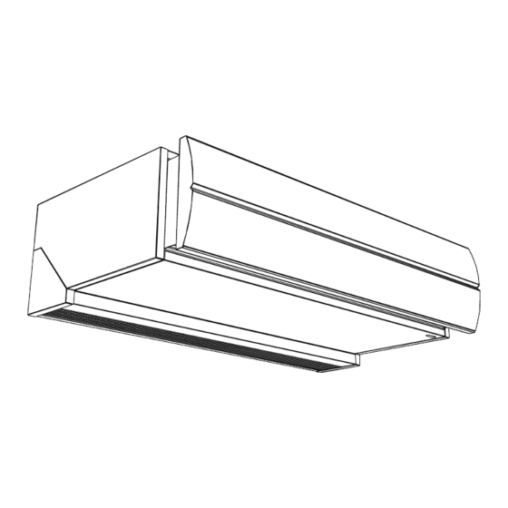
- Page 1 Installation, Operating And Maintenance Manual Comfort Air Curtain Model DF2 English Version 1.0 Original Manual...
-
Page 2: Table Of Contents
Switching the unit ON and OFF Controlling the fan speed Control temperature or heating Maintenance Cleaning the unit Scheduled maintenance Errors Safety instructions Resolving simple problems Remedying faults Service Safety instructions Access Fuses Resetting the high-limit thermostat Biddle control cable composition en-2... - Page 3 DF M ANUAL Dismantling Addresses Keywords Installation, Operating And Maintenance Manual version 1.0 (16-08-2023) en-3...
-
Page 4: Introduction
Introduction About this manual This manual describes the installation, operation and mainte- nance of the Model DoorFlow Comfort air curtain. The man- ual also provides instructions and information about servicing. How to read this manual 1.2.1 Designations used in the manual The following symbols are used in the manual: Note: Refers to an important section in the text. -
Page 5: About The Unit
DF M ANUAL NTRODUCTION 1.2.2 Symbols used on the unit and in the manual The following symbols indicate possible risks or hazards. The same symbols will also be found on the unit. YMBOL ESCRIPTION You have accessed a section of the unit containing compo- nents which carry a voltage. - Page 6 Warning: Applications other than those described above are deemed to be ‘usage other than for the intended purpose’. Biddle is not liable for damage or loss resulting from usage other than for the intended purpose. Usage for the intended purpose also entails observance of the instructions in this manual.
- Page 7 DF M ANUAL NTRODUCTION YPE CODE ELE ESIGNATION EANING MENT heating type hot water electrical ambient model free-hanging model cassette model recessed model 1.3.3 Type plate The type plate is located on the top of the unit. Designations on the type plate ESIGNATION EANING Type...
-
Page 8: Restrictions On Use
NTRODUCTION OMFORT URTAIN (and UKCA where appropriate) declaration is no longer valid if the unit has been modified or changed in any way. 1.3.6 Components and accessories For all models (optional): • control panel (can be used for multiple units) •... - Page 9 Where this is not possible and higher water temperatures are used Biddle recommend the unit’s casework should be tested to ensure that it doesn’t become too hot with the potential to cause burns. Children aged from 3 years and...
-
Page 10: Safety Instructions
NTRODUCTION OMFORT URTAIN Safety instructions 1.5.1 Safety in use Warning: Do not put any objects into the inlets and outlets. Warning: Do not obstruct the unit’s inlets or outlets. Warning: The upper surface of the unit becomes hot during operation. Caution: In exceptional situations, water may run out of the unit. - Page 11 DF M ANUAL NTRODUCTION 5. For water-heated models: isolate the water connections. Warning: The fins of the heat exchanger are sharp. Installation, Operating And Maintenance Manual version 1.0 (16-08-2023) en-11...
-
Page 12: Installation
Ensure that all components are present. Notify supplier of any missing parts immediately. General working method 2.3.1 Sequence of operations Biddle recommends working as follows when installing the unit: 1. Hang the unit up. 2. For models with water-heating (type W) : connect the unit to the central heating system. -
Page 13: Hanging The Unit Up
DF M ANUAL NSTALLATION 6. Switch the mains supply on and check that the unit is working properly. 7. Connect the unit to any building management systems (if required). General instructions Some parts of this section only apply to certain models. Where this is the case, it will be indicated. - Page 14 NSTALLATION OMFORT URTAIN • Note the following dimensions: The unit must be at least as wide as the door opening (dimension b). Position the unit as near to the doorway as possible. Position the unit as close to the top of the door as pos- sible.
- Page 15 DF M ANUAL NSTALLATION 2.4.2 Mounting the optional remote control 1. Identify a suitable place for the wall controller to be mounted. This should be away from direct sunlight in a place where tampering is not likely to affect the operation of the unit.
-
Page 16: Connecting The Unit To The Central Heating System
NSTALLATION OMFORT URTAIN Dimensions of hole and suspension for cassette model SIZE TYPE DIMENSIONS 100-C 1012 mm 150-C 1512 mm 200-C 2012 mm 250-C 2512 mm all DF 705 mm 100-C 937 mm 150-C 1437 mm 200-C 1937 mm 250-C 2437 mm all DF 641 mm... - Page 17 DF M ANUAL NSTALLATION 2.5.1 Special points Caution: The central heating system’s supply and return pipes must be attached to the correct corresponding connectors 1. On the unit, the directions are indicated with arrows. • Keep the connectors 1 in place by using pliers when con- necting the pipes.
-
Page 18: Connecting The Unit To The Mains Supply
NSTALLATION OMFORT URTAIN 1. Connect the unit and the two-way valve to the central heating system as shown in the diagram. 2. Connect the valve’s plug to the unit’s plug. 3. Open the valve manually using the handle (Position ‘MAN’). 4. - Page 19 DF M ANUAL NSTALLATION For electrically heated models: Warning: Do not turn unit ON/OFF at its power supply. Use the control panel. • Connect the unit to the mains using a power cable (not supplied). Maximum ratings are specified on the type plate. •...
-
Page 20: Installing The Control Panel And External Controls
NSTALLATION OMFORT URTAIN 2.6.3 Connecting the unit For water-heated models (type W) and models with- out heating (type A): 1. Insert the plug into the power socket only after installa- tion has been completed. For electrically heated models (type E): Warning: Only connect the unit if you are qualified to work on three-phase power systems. - Page 21 • A maximum of eight units may be connected to a single control panel. • Units are daisy chained using Biddle control cables and connectors • The total length of the control cables (from the control panel to the last unit connected) may not be any longer than 30 m.
- Page 22 NSTALLATION OMFORT URTAIN 2.7.2 Unit settings Warning: Disconnect the unit from the power supply before making any changes. Several dip switches are located on the unit’s control circuit board. You can use these to change the operation of the unit. FUNCTION POSITION ON POSITION OFF...
- Page 23 DF M ANUAL NSTALLATION 2.7.3 External control inputs The inputs are suitable for potential-free switches, which can be connected using a 2-core cable. Note: Leave approximately 20cm of slack in the cable above the unit to make serving the unit easier in the future.
- Page 24 NSTALLATION OMFORT URTAIN Working of the input DIP 4 FUNCTION CONTACT CLOSED CONTACT OPEN ON (ON) Door contact switch Door is closed: Door is open: • heating switches off • unit operates normally after 30 sec. (by remote control) • fans switch to low speed after 30 sec.
-
Page 25: Finishing The Unit
DF M ANUAL NSTALLATION contact is open (heating switched off) when the out- door temperature is higher than the set temperature on the thermostat. 5. DIP switch 4 on the control circuit board must be set to OFF(off) (see Unit settings). - Page 26 NSTALLATION OMFORT URTAIN 2.8.1 Edge finishing Only for cassette model (type C): 1. Make a hole in the ceiling for the unit. Dimensions of hole and suspension for cassette model SIZE TYPE DIMENSIONS 100-C 1012 mm 150-C 1512 mm 200-C 2012 mm 250-C 2512 mm...
-
Page 27: Power On And Check Operation
DF M ANUAL NSTALLATION SIZE TYPE DIMENSIONS 100-R 970 mm 150-R 1470 mm 200-R 1970 mm 250-R 2470 mm 2. Attach the two angle sections 1 to the unit along the dis- charge openings' edges using the screws supplied. 3. Extend the telescopic discharge grille 2 into the unit’s dis- charge opening until it reaches the required height. - Page 28 NSTALLATION OMFORT URTAIN If applicable: external controls. 3. Turn on the power supply and/or put the plug in the socket for all connected devices. 4. Start up the air curtain with the control panel. 5. Check that all connected appliances blow air across the entire width of each appliance.
-
Page 29: Operation
Operation Introduction This section describes the functions you should know for the day-to-day use of the unit. The control panel is provided with four touch-buttons. These keys allow the user to make the following settings: • Switching the unit ON and OFF: button ≡. •... -
Page 30: Control Temperature Or Heating
PERATION OMFORT URTAIN Control temperature or heating Automatic or manual control • Press briefly on button ≡ to switch the unit between auto- matic ( A) and manual mode ( M). Automatic temperature control This temperature is measured at the unit’s air inlet and may deviate slightly from actual room temperature. -
Page 31: Maintenance
Maintenance Cleaning the unit You can clean the exterior of the unit with a damp cloth and a domestic cleaning agent. Do not use any solvents. Caution: Make sure that no water runs into the unit. Scheduled maintenance It is recommended to have the following inspection and main- tenance activities performed annually by an installer or other technical expert. -
Page 32: Errors
Errors Safety instructions Danger: All work on the inside of the unit may only be carried out by personnel who are technically qualified to do so. Warning: Before you begin: read the safety instructions. See also: "Safety instructions" on page 9 Resolving simple problems If you suspect a malfunction, first try to resolve the problem using the table below. -
Page 33: Remedying Faults
DF M ANUAL RRORS ROBLEM ROBABLE CAUSE OLUTION The unit is not working and the The unit is switched off. Turn the unit on. control panel LEDs are off. The unit has no power supply. Check the mains supply: • is the plug in the socket? •... - Page 34 RRORS OMFORT URTAIN Fault rectification (for qualified technical staff only) PROBLEM POSSIBLE CAUSE SOLUTION The control panel works normally The power supply to the fans is cut 1. Check the fuses on the control but the unit does not respond. off.
- Page 35 DF M ANUAL RRORS PROBLEM POSSIBLE CAUSE SOLUTION Not all connected units are working The control panel is not communi- 1. Check that power is supplied to (or only partially). cating with one or more connected all connected units. units (or with one of the control 2.
- Page 36 RRORS OMFORT URTAIN PROBLEM POSSIBLE CAUSE SOLUTION The unit (or part of the unit) is For electrically heated units: 1. Check and reset the tempera- blowing cold air. The temperature cut-out has ture cut-out. The LEDs on the control panel are turned the unit (or part of the unit) 2.
-
Page 37: Service
Service Safety instructions Warning: Servicing activities may only be carried out by personnel who are technically qualified to do Warning: Before you begin: read the safety instructions. See also: "Safety instructions" on page 9 Access 6.2.1 Removing the front panel For free-hanging models only: 1. - Page 38 ERVICE OMFORT URTAIN 6.2.2 Opening the unit For free-hanging models (type F) and recessed mod- els with electrical heating (types E-R) and models without heating (types A-R) 1. Remove the front panel, if necessary. 2. Remove the inlet grille 4. For cassette models (type C) 1.
- Page 39 DF M ANUAL ERVICE For all models 1. Remove the screws along the edge of the inspection panel. 2. Pull the panel forward a little and remove it. Caution: The entire panel comes free once pulled forward – make sure it does not fall. 6.2.3 Removing the control circuit board With all units: 1.
-
Page 40: Fuses
ERVICE OMFORT URTAIN 2. Remove the control circuit board 2. 3. Disconnect all unit-connected connectors and grounded connections from the control circuit board. For electrically heated units: 1. Disconnect all connectors and earth contacts connecting the unit and control circuit board 1. 2. -
Page 41: Resetting The High-Limit Thermostat
The unit will then start as normally and the alarm symbol in the bottom left of the control panel will stop flashing. The sta- tus LED on the circuit board inside the unit flashes green. Biddle control cable composition The control cable for the control system is constructed as fol- lows: •... - Page 42 Dismantling The dismantling of the installation and the handling of the coolant, oil and other components must be carried out by a qualified fitter in accordance with the relevant local and national legislation and regulations. Pursuant to EU legislation, used electrical and electronic appli- ances must be collected for recycling.
- Page 43 Addresses If you have any comments or queries relating to this product, please do not hesitate to contact your Biddle branch. Biddle bv P.O. Box 15 9288 ZG Kootstertille The Netherlands Biddle bv Biddle Air Systems Ltd. P.O. Box 15 St.
- Page 44 DDRESSES OMFORT URTAIN T +31 (0)512 33 55 55 E info@biddle.nl Biddle Air Systems St. Mary’s Road, Nuneaton Warwickshire CV11 5AU United Kingdom T +44 (0)24 7638 4233 E sales@biddle-air.co.uk I www.biddle-air.co.uk en-44...
- Page 45 DF M ANUAL DDRESSES Biddle France 21 Allée des Vendanges 77183 Croissy Beaubourg France T +33 (0)1 64 11 15 55 E contact@biddle.fr I www.biddle.fr Biddle GmbH Emil-Hoffmann-Straße 55-59 50996 Cologne Germany Installation, Operating And Maintenance Manual version 1.0 (16-08-2023)
- Page 46 DDRESSES OMFORT URTAIN T +49 (0)2236 9690 0 E info@biddle.de I www.biddle.de en-46...
- Page 47 DF M ANUAL Keywords accessories ......8 installation ......12 addresses .
- Page 48 OMFORT URTAIN service ......37 suspension ..... 13, 15 symbols .
- Page 49 DF M ANUAL Installation, Operating And Maintenance Manual version 1.0 (16-08-2023) en-49...
- Page 50 It helps us to improve the documentation still further. For more information If you have any comments or queries relating to this product, please do not hesitate to contact Biddle. You will find the contact information for your Biddle branch in the Addresses chapter.
Need help?
Do you have a question about the DF2 and is the answer not in the manual?
Questions and answers