Table of Contents
Advertisement
Quick Links
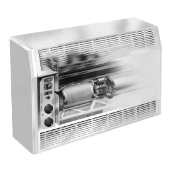
Forceflow 900
Series
Fan Convector
Installation Operating
& Maintenance
For specific unit mounting model, please refer to
the brochure or contact Biddle (024 7638 4233)
UNPACKING
Remove protective cardboard outer packaging
and any polystyrene padding.
You should have received your fan convector
in perfect condition. Please advise us within
24 hours of receipt if it is damaged in any
way whatsoever.
TOOLS REQUIRED
We suggest the following tools are used
during installation :
• posi-drive screwdriver
• flat-head electrical screwdriver
• 7mm and 10mm nut-driver/socket and ratchet,
with 75mm and 450mm extension pieces
INSTALLATION
1 Remove the access panel by unscrewing
the 2 x retaining screws, or unlocking the
2 x key operated locks, within the front of
the casing
2 Securely fix the unit to the wall or ceiling
using the four fixing holes on the rear
3 Check whether the water connections are
on the most appropriate side of the unit.
If not, change the 'handing' following the
instructions overleaf
4 Using proprietary fixings, connect the flow
and return pipework to the coil (it is usual
to have the water flow connection on the
air leaving side of the coil), bringing the
pipework in through the holes in the base
of the unit - connections are all sized
Female BSP
5 Test and vent the coil to expel any air from
the system
6 Feed the power supply cable, and any
other necessary wires (eg remote switch
box, remote thermostats etc), through the
casing utilising the cable gland supplied,
and use the plug supplied to blank off the
hole on the opposite end of the unit
7 Remove the black/yellow electrics box by
unscrewing the 2 x retaining M5 hex bolts
8 Locate the wiring diagram on the fan scroll
9 Carefully following the wiring diagram connect the power supply, and any other
necessary items (eg remote switch box, remote thermostats), to the terminal block
within the black/yellow electrics box
10 Check the electrical connections and supply power
11 Refix the electrics box
12 Set the neon on/off switch to the 'on' position
13 Set the speed control switch, typically, to the 'low' position
14 Set the summer/winter switch to the appropriate position (see note on back page)
15 Set the on/off thermostat to, typically, 20°C
16 Set the speed change thermostat to, typically, 16°C
17 Re-fix the access panel
MAINTENANCE
Before carrying out any maintenance work it is obviously important to isolate the unit
from the power supply, and to ensure it cannot be accidentally restored by
3
/
"
4
unauthorised personnel.
The standard cardboard frame panel filter is not designed to be cleaned, and should
be replaced at appropriate intervals, which will vary from site to site.
The coil and fans should be cleaned by vacuuming, again at appropriate intervals.
SPARES
Biddle will supply spares for the Forceflow 900 Series fan convector for at least 5
years from the date of manufacture of the unit.
When ordering spares please state the model and serial number from the silver
identification label inside the unit.
Advertisement
Table of Contents

Related Manuals for Biddle Forceflow 900 Series


Summary of Contents for Biddle Forceflow 900 Series
- Page 1 (eg remote switch box, remote thermostats etc), through the Biddle will supply spares for the Forceflow 900 Series fan convector for at least 5 casing utilising the cable gland supplied, years from the date of manufacture of the unit.
- Page 2 On/off (T1) thermostat – this is usually set to around 20°C. Once room temperature Biddle Air Systems Limited reaches this setting the fans automatically turn off. St. Mary’s Road, Nuneaton Speed change (T2) thermostat –...
- Page 3 Changing the Unit Handing Steps 1 - 9 1 Removing Access Panel 2 Removing Top Panel 3 Removing Filter 4 Removing Blanking Plates 5 Removing Coil 6 Removing Electrics Box 7 Removing Fan Deck 8 Removing Fan Brackets 9 Moving Fan Brackets...
- Page 4 Changing the Unit Handing Steps 10 - 18 10 Changing Coil Handing 11 Re-attaching Fan Deck 12 Changing Electrics Box Handing 13 Re-attaching Electrics Box 14 Re-attaching Coil 15 Re-attaching Blanking Plates Clip T4 thermostat on return bends of coil. Coil is attached to back plate using 4x M6 nuts.
Need help?
Do you have a question about the Forceflow 900 Series and is the answer not in the manual?
Questions and answers