Table of Contents
Advertisement
Quick Links
Advertisement
Table of Contents

Subscribe to Our Youtube Channel
Related Manuals for Brooks Marathon Express


Summary of Contents for Brooks Marathon Express
- Page 1 Marathon Express™ User Manual Part Number 605914 Rev. B...
- Page 2 Marathon Express Part Number: 605914 Rev. B Brooks Automation, Inc. Information provided within this document is subject to change without notice, and although believed to be accurate, Brooks Automation, Inc. assumes no responsibility for any errors, omissions, or inaccuracies. ABF™, AcuLigner™, Advan Tag™, Align™, AutoTeach™, ATR™, AXM™, Basic Blue™, BiSymmetrik™, CenterSmart™, Crate to Operate™, CrossingConnect™, DARTS™, E nerta™, e-RMA™, e-Spares™, e- Volution™, F alcon™, FastRegen™, FIXLOAD™, FrogLeg™, Independent Twin Linear Exchange™, InLigner™, Interface™, I soport™, ITLX™, Jet™, Jet Engine™, LEAP™, LowProfile™, M2 Nano™, PASIV™, PowerPak™, PerformanceBlue™, Plate Auditor™, PowerPak™, PowerTools™, PuroMaxx™, QuadraFly™, Radius™, Radient™, Radient Express™, Reliance™, Reliance ATR™, RetroEase™, SCARA™, SmartPM™, SPOTLevel™, Sprint™, Synetics™, The New Pathway to Productivity™, Time Optimized Trajectory™, Time Optimal Trajectory™, Time Optimized Path™, TopCooler™, TopLigner™, Ultimate Blue™, VAC-407™, VacuTran™, VersaPort™, and WaferEngine™ are trademarks of Brooks Automation, Inc. AcuTran®, A syst®, Crossing Automation®, Fusion®, GOLDLink®, Guardian®, H elix®, L eapfrog®, MagnaTran®, ...
- Page 3 Chelmsford, MA 01824 U.S.A. For Technical Support: Location Contact Number Website +1-800-447-5007 (Toll Free) North America +1-978-262-2900 (Local) +49 800 000 9347 (Toll Free Germany) Europe +49 364 176 9999 6 (Has Toll) +81 120-255-390 (Toll Free) Japan +81 45-330-9005 (Local) http://www.brooks.com/ China +86 21-5131-7066 +886 080-003-5556 (Toll Free) Taiwan +886 3-5525258 (Local) Korea 1800-5116 (Toll Free) +65 1-800-4-276657 (Toll Free) Singapore +65 6309 0701 (Local) Contact Technical Publications directly: Technical.Publications@brooks.com Accelerating Innovation Copyright © 2023, Brooks Automation, Inc.
- Page 4 Zhangjiang Hi-Tech Malaysia Brooks Automation Ltd. (Germany) GmbH Park P udong, Shanghai ...
- Page 5 Brooks Automation Part Number: 605914 Rev. B Revision History Revision Date Action Author EC146354 6/29/2023 Initial release. K. Forscher Added AC Power Distribution information to the EC146805 7/13/2023 K. Forscher Operational Interfaces and Operation chapters. Copyright © 2023, Brooks Automation, Inc.
-
Page 6: Table Of Contents
Mechanical Specifications Electrical Specifications Chamber Heating and Cooling Facilities Specifications Communications Specifications Center of Gravity and Floor Loading Site Requirements for Moving the Marathon Express Process Module Space Allocation Service and Exclusion Zones 2. Safety Regulatory Compliance and Declaration of Incorporation Explanation of Hazards and Alerts Safety Text Safety Icons Signal Words and Color Alert Example General Safety Considerations Illustration of Hazard Locations Safety and Identification Labels Illustration of Hazard Locations Interlocks Lockout/Tagout Mechanical Hazards Lid Lockout/Tagout Procedure Electrical Hazards Disconnect Devices Laser Hazards Thermal Hazards Vacuum Hazards Ergonomics Hazards Tip Hazard Environmental Information Noise Emission Vibration Copyright © 2023, Brooks Automation, Inc. - Page 7 Installation Procedure Procedure Category Required Tools and Equipment Remove Protective Packaging Removing Shipping Brackets Installing the Vacuum Cassette Elevators Installing the Marathon Express Mounting the Process Modules to the MX System Intermodule Connections Facilities Connections Electrical EMO Circuit Communications Connections Power-up Sequence 4. Subsystems System Overview Transport Chamber Transport Chamber Lid Assembly Lid Operation Frame Assembly Power Distribution AC Power Distribution Circuit Protection Vacuum Systems Pumping System Chamber Isolation Valves Venting System Vacuum Measurement System Gauges Vacuum System Control Pneumatic System Gas System Water System Transport Chamber Heating System Copyright © 2023, Brooks Automation, Inc.
- Page 8 Material Presence Sensors MagnaTran 7 or LEAP Vacuum Robot Control/Display Module Vacuum Load Locks 5. Operational Interfaces Heater Power Supply Remote AC Power Distribution Power Connections AC Power Distribution Cable 6. Operation Theory of Operation Station Coordinate System Marathon Express Frames of Reference Robot’s Frame of Reference Aligner’s Frame of Reference System Operation Overview Determining Material Locations Pick and Place Commands Material Presence Sensing Wafer Mapping Radial Motion Sensors Controls and Indicators AC Power Distribution Heater Power Supply Temperature Controller Ethernet to Serial Gateway Module Ethernet Switch Module Safety Interlocks Lid Open Emergency Off (EMO) Circuit Lid Lifter Operation Raising the Lid Lowering the Lid Control/Display Module (CDM) Operation Copyright © 2023, Brooks Automation, Inc.
- Page 9 Wafer Cooling System Pneumatic (Air Distribution) System Gas Facilities Operation Controls and Indicators TopCooler Operation TopLigner Vacuum Aligner Operation Vacuum System Operation Initial Conditions Chamber Bakeout Start-up Exchange Wafers in the Load Locks Shut down from high vacuum Vent Transport Chamber Vent Load Locks Venting the Chambers - Profiled Vent Start-up Normal Running 7. Command Reference 8. System Alignment Overview Procedure Category Required Tools and Test Equipment Alignment Strategy Alignment Overview Alignment Process Level the VCE Platforms Level the Process Modules and Dock to the Marathon Express Adjust the Robot’s End Effectors System Preparation Initializing the Vacuum Cassette Elevators Initializing the TopLigner Initializing the TopCooler Initiating the CDM Opening the Chamber Lid Copyright © 2023, Brooks Automation, Inc.
- Page 10 Adjust the Load Lock Platform Set the Load Lock T and R Coordinates Align the Load Lock’s SPS Teach the Robot the Integral Wafer Buffer Station Procedure Teach the Robot the Process Modules Procedure Teaching Pan ’B’ on a Dual End-Effector Arm Set Fine-Tuning the Station Assignment Using the Aligner as a True Position Reference Using Physical Location as a True Position Reference System Alignment Check-out Alignment Procedure 9. Maintenance and Repair Preventative Maintenance Parts Pad Cleaning Procedure Maintenance Procedure Cleaning Procedure Maintenance Procedure TopCooler Cool Chuck Cleaning Maintenance Procedure O-Ring Removal/Replacement/Cleaning Maintenance Procedure Verifying Flatness of Robot’s End Effector Measurement Procedure Adjusting the Robot’s End Effector(s) Adjustment Procedure Repair Philosophy Repair Procedures Wafer Change-Over Procedure Maintenance Procedure Removing/Replacing Viewports Lid Replacement Copyright © 2023, Brooks Automation, Inc.
- Page 11 Brooks Automation Part Number: 605914 Rev. B Lid Lifter Replacement Vacuum Robot, Arm, or End Effector Replacement Pad Removal/Replacement Heater Cartridge Replacement TopCooler Poppet Open/Close Sensor Adjustment TopLigner Support Pin Replacement Isolation Valve Replacement 10. Troubleshooting Initial Troubleshooting Interlocks Material Transport TopLigner Vacuum Aligner Pressure/Indicator Switch Vacuum System 11. Field Replaceable Units Marathon Express 12. Appendices Appendix A: Contact Brooks Automation Technical Support Appendix B: Factory Default Settings Default Robot Settings Default VCE 6 Drive Settings Default TopLigner Vacuum Aligner Settings Appendix C: Station Identification Appendix D: Document Abbreviations Appendix E: Consumables Appendix F: Packing and Shipping Instructions Packing Procedure Appendix G: Material Safety Information Copyright © 2023, Brooks Automation, Inc.
-
Page 12: Introduction
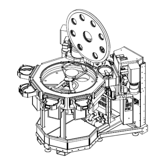
1. Introduction Marathon Express System Overview Part Number: 605914 Rev. B 1. Introduction This Introduction provides a brief overview of the Brooks Automation Marathon Express™ Cluster Tool Integration Platform highlighting its features, components, operation, and specifications. Additionally, the chapter organization and a description of each chapter’s contents is presented, and notation conventions are explained. This Marathon Express is intended for use by industrial customers and should be serviced only by Brooks or Brooks trained representatives. The service manuals and related materials are provided in English at no charge and are intended for use by experienced technicians. It is the responsibility of the user to obtain and assure the accuracy of any needed translations of manuals. If you require assistance please contact Brooks service department. Contact information can be found at www.brooks.com. System Overview The Brooks Automation Marathon Express (MX) Cluster Tool Integration Platform transfers 100 mm to 200 mm wafers or 100 mm to 150 mm square substrates from a Vacuum Cassette Elevator Load Lock into a Vacuum Back End for access to multiple Process Modules for multi-step processing without leaving the vacuum environment. The MX system provides SEMI-standard compatible process module and material carrier interface systems, with a full set of options, to meet factory interface requirements. The Brooks Automation MX system is designed for use in a vacuum transport cluster tool system. The full Marathon Express system includes the cluster tool platform that accommodates up to 6 Process Modules, two vacuum cassette elevators, and a vacuum robot. Figure 1-1 shows a Marathon Express Cluster Tool with all Brooks Automation components. Copyright © 2023, Brooks Automation, Inc. -
Page 13: Options
Brooks Automation 1. Introduction Part Number: 605914 Rev. B System Overview Figure 1-1: Brooks Automation Marathon Express The SEMI S2 and CE regulatory compliant Marathon Express Cluster Tool Integration Platform offers integral support for all system structures. The integrated frame architecture of the MX system supports standard OEM SEMI roll up style process modules with standard interfacing to frame and facet and MESC bolt on style process chambers. Options TopCooler (wafer cool module) VX Aligner (vacuum aligner) Complete slot valve/process module/robot hardware interlocking depending on System Integration Level Subsystems The Marathon Express is made up of several functional subsystems designed for ease of use, maintenance, and repair. These subsystems are modular in design to allow ease of maintenance and to minimize Mean Time To Repair (MTTR). The individual modules that make up the MX system are described briefly below and in detail in "Subsystems". Marathon Express™ Vacuum Transport System The Brooks Automation Marathon Express Vacuum Back End is a multifaceted Cluster Tool Integration Platform utilizing proven Brooks components such as the VCE vacuum cassette elevator and MagnaTran LEAP vacuum robot. Copyright © 2023, Brooks Automation, Inc. - Page 14 VCE 6 Vacuum Cassette Elevator The Brooks Automation VCE allows SEMI standard H-bar wafer cassettes to be introduced into, and removed from, the high-vacuum environment of the Transport Module without disturbing that vacuum environment. The VCE consists of a wafer cassette elevating mechanism housed in an aluminum vacuum load lock chamber. The elevator raises or lowers a cassette so that individual slots are aligned with the system Material Transport Plane for wafer transport by the vacuum robot. See the VCE User Manual for more information on the VCE. See the robot manual for more information on the robot. Vacuum Aligners TThe vacuum aligners accept randomly-oriented wafers and rotates them while scanning for fiducial location and eccentricity. Using the eccentricity information provided the robot can then pick up the wafer using an offset to center the wafer on the end effector. Wafer Cool Station The Brooks Automation TopCooler is designed to cool wafers in SEMI-standard 100 mm through 200 mm sizes prior to further processing or reinsertion into a cassette. The cooling cycle involves discharging a fixed quantity of gas into the closed cool chamber, which provides conductive heat transfer between the gas and a chill plate to cool the wafer. Controls The Marathon Express is available with several different control configurations. These configuration are described briefly below and in detail in "Electrical System" on page 97. Configuration The configuration of the Marathon Express is determined by the user and is based on the Basic Configuration needed and the System Integration Level required. Basic Configuration The Basic Configuration of the Marathon Express is determined by thewafer size and the number of Process Modules (PMs) accommodated. System Integration Level The System Integration Level is determined by the user’s requirements for system integration and controls and is available in Levels as described below. This manual provides complete coverage for the hardware used in all integration levels of the Marathon Express and the software used through the Level 2.5 integrated systems. Copyright © 2023, Brooks Automation, Inc.
-
Page 15: Supplementary And Related Documentation
Level 2.5 - Marathon Express with Electrical Integration This level of integration provides complete Electrical Integration, including Controls Wiring and System Power. This system includes all components, integration, and testing for a complete Controls solution. Level 2.5 provides a complete component set including all cabling and complete Power Distribution as detailed below. All Level 2 items Connector panel with internal wiring and power distribution Supplementary and Related Documentation This user manual provides documentation for operation and maintenance of the Brooks Automation Marathon Express Cluster Tool Integration Platform. While this document covers specific information and adjustments for the Marathon Express, there may be information in other manuals which affect the settings or operating mode of the MX system and the attached components. The Marathon Express is set to system specifications and acceptance tested at Brooks Automation. Before adjusting or changing settings on a Marathon Express, consult the following documentation: Brooks Automation robot manuals Brooks Automation VCE U ser Manual OEM Components Manuals (supplied with this manual) Process Module User Manual Process Module Controller User Manual Transport Controller User Manual Copyright © 2023, Brooks Automation, Inc. -
Page 16: Manual Notation
Supplementary and Related Docu- Part Number: 605914 Rev. B mentation NOTE: All documents cited should be the latest revision. This manual is intended to provide information about a wide variety of Marathon Express configurations and options. It may contain references to items not installed on a specific system. The commands for controlling the robots and other components used in the Marathon Express are defined in their user manuals. This user manual may refer the reader to these manuals for additional information. This manual contains, as addendums and attachments, customized documents for a specific build of the Marathon Express. These documents are provided to allow service personnel to identify specific parts within the system and aid in maintenance and troubleshooting. This manual and all addendums and attachments are not controlled. Changes may have been made or additional documents or drawings added to the system documentation at any time. To identify the current revisions or to obtain a current set of drawings and documents, contact Brooks Automation Customer Support. Manual Notation This manual uses a standard notation system to provide consistent descriptions of all items and functions associated with all Brooks Automation devices. These standards include; hardware notation, software notation, and descriptive warnings. These notation standards identify tasks to be performed by the user during a service, installation, or operation procedure, or as a specific input to the Marathon Express. In applications where “should” or “shall” is used, conformance to this application is required. Where “may”, “suggested”, or “preferred” is used, conformance is not required. Copyright © 2023, Brooks Automation, Inc. -
Page 17: Specifications
NOTE: These dimensions are for standard MX system Range of Motion configurations, dimensions can vary for customized configurations Maximum Noise Level 55 dB (A) 900 mm at VCE platform (SEMI standard) Transport Plane 1100 mm (43.31 in) per SEMI E21 at Process Module side (3.78 mm (0.15 in) above slot centerline) 100 mm 25 mm Material Sizes (wafers) 150 mm 200 mm with or without notched fiducial per SEMI M1 100 mm square Material Sizes (substrates) 125 mm square 150 mm square 400g maximum with BiSymmetrik arms Material Weight 200g maximum with Leapfrog arms 6 mm maximum with BiSymmetrik arms Material Thickness 3 mm maximum with Leapfrog arms Material Transparency 0 to 96% MX 800: Approximately 117.7 liters (7,184 in3) Vacuum Chamber Volume (typical values MX 700: Approximately 117.1 liters (7,150 in3) shown, can vary based on configuration): MX 600: Approximately 69.0 liters (4,212 in3) VCE 6: Approximately 50.0 liters (3,051 in3) (each) Copyright © 2023, Brooks Automation, Inc. -
Page 18: Environmental Specifications
Alignment time: 4.8 sec (wafer) 9 - 13.8 sec (square substrate) Thermal Transfer Gas: Argon, Nitrogen (factory) optional Wafer Cooler Module Gas Delivery Pressure: 20 psi max Gas Consumption: 2 cc/cycle at regulator pressure Integral Wafer Buffer Station Capacity: 4 wafers at 5.5 mm (0.22 in) pitch Capacity: 4 wafers at 6.0 mm (0.236 in) pitch Buffer Station Volume: Approximately 4.5 liters (276 in Mounting: Facet mount with slot valve and atmospheric door Small Volume Lock Volume: Approximately 12.0 liters (732 in Environmental Specifications ISO 14644-1 Class ISO 6 or better cleanroom ambient. Table 1-2: Environmental Specifications Specification Value Operating: 20° C to 30° C (68° F to 86° F) Temperature Shipping: -25° C to 55° C (-13° F to 131° F), up to 65° C (149° F) for 24 hrs. max Storage: -25° C to 55° C (-13° F to 131° F), up to 65° C (149° F) for 24 hrs. max Humidity 30% to 55% (relative, non-condensing) Standard lighting provided in the cleanroom environment where the Marathon Express is Lighting installed is sufficient for proper operation. Maintenance may require a user-supplied service light (i.e., flashlight). Copyright © 2023, Brooks Automation, Inc. -
Page 19: Mechanical Specifications
Stainless Steel, Cold Rolled Steel, Baked Powder Coated Epoxy, 7740 Pyrex®, 7056 (Atmosphere) Glass, Viton®, Lexan® 6061 T6 Aluminum, 5080R Aluminum, 316 Stainless Steel, AM350 Stainless Steel, Sintered Exposed Materials Nickel, Electroless Nickel Plate, 7740 Pyrex, 7056 Glass, BK7 Glass, Teflon®, Viton, (Vacuum) Kalrez®, Tinned Copper Wire, Quartz (TopCooler option) 100 mm, 125 mm, 150 mm, and 200 mm Cassette Type SEMI standard cassettes 25 or 26 wafer cassette configurations At VCE interface panel As specified by user At Marathon Express Vacuum Transport System ISO 160 Port for High Vacuum Pump ISO 200 Port for High Vacuum Pump Vacuum Ports KF 50 Port for Venting KF 40 Port for Rough Pump KF 25 Port for Material Sensor (x facet number) KF 25 Port for Vacuum Gauging (x 2) KF 16 Port for Vacuum Gauging (x 2) 1/4 inch VCR fitting at Nitrogen Facilities Connection Nitrogen Port To support venting capacity, a minimum of a 3/8 inch O.D. line is required with a reducer to connect to the 1/4 inch VCR fitting. Argon Port 1/4 inch VCR fitting at TopCooler Facilities Connection Pneumatic Port 10 mm Quick Connect Water 1/2 inch OD tubing, Swagelok interface Copyright © 2023, Brooks Automation, Inc. -
Page 20: Electrical Specifications
Adjustable feet to meet WTP Leveling Provision -0.4/+1.0 inch range Rolling Provision 3 casters, removable Lifting Provision Built-in fork tubes, one-side access Hold-down Pro- User supplied and installed brackets visions Electrical Specifications Overvoltage Category Table 1-4 describes electrical overvoltage categories. Brooks Automation has designed the Marathon Express as an Overvoltage Category II device. Table 1-4: Overvoltage Category Category Description Signal level (special equipment or parts of equipment, telecommunications, etc.) with smaller tran- Category I sient overvoltages than Overvoltage Category II. Local level (appliances, portable equipment, etc.) with smaller transient overvoltages than Over- Category II voltage Category III. Distribution level (fixed installation, building wiring, etc.) with smaller transient overvoltages than Category III Overvoltage Category IV. Category IV Primary supply level (overhead lines, cable systems, etc.). Copyright © 2023, Brooks Automation, Inc. -
Page 21: Chamber Heating And Cooling
120° C to 40° C in 2 hours (with water cooling option) (for base system as supplied by Cool-down Time Brooks Automation only, does not include any user attached modules) Facilities Specifications Table 1-6: Facilities Specifications Specification Value Typical configurations require the following supply of clean, dry (unfiltered), oil free air: Pneumatic 90 psig ±10 psig at 50 slm nominal, 200 slm maximum Typical configurations require the following supply of clean, dry nitrogen: Nitrogen <1 ppm contamination 40 psig ±5 psig at 100 slm nominal, 300 slm maximum Configurations using a facet mounted TopCooler may require the following supply of clean, dry argon: Argon <1 ppm contamination 20 psig -5/+0 psig at 10 sccm Typical configurations require the following differential vacuum supply (input to vacuum Vacuum, Backing aligner seals) 635 mm Hg at 50 cc/sec (25 in Hg at 3.05 ci/sec) Pumping speed, 900 lpm (32 cfm) minimum Vacuum, Rough Ultimate pressure, < 23 mTorr Pumping speed, 900 lpm (32 cfm) minimum Vacuum, Foreline Ultimate pressure, < 23 mTorr Copyright © 2023, Brooks Automation, Inc. - Page 22 UL489/IEC60947-2 compliant branch circuit breaker (circuit breaker supplied with Gen 5 EN system ACPD is 5,000 AIC). Electrical System Europe, Korea, Israel: 220 - 240V AC @ 50/60 Hz, single phase (phase to neutral), 8 A, based on configuration and operating mode. Inrush current < 38 A max for 1/2 to 1 cycle Overvoltage Category II The system must be installed on the load side of a user-supplied 10,000 AIC rated, UL489/IEC60947-2 compliant branch circuit breaker (circuit breaker supplied with Gen 5 EN system ACPD is 5,000 AIC). Three phase star (Y) connection: 50/60 Hz (Europe, Korea, Israel) 220 VAC @ 9.45 A per phase, total power 5.7 kVA 230 VAC @ 9.88 A per phase, total power 6.2 kVA 240 VAC @ 10.31 A per phase, total power 6.8 kVA Heater Power Supply incorporates a 10,000 AIC rated, UL489/IEC60947-2 compliant, branch curcuit breaker. Electrical Heater Delta connection: 50/60 Hz (Japan, USA) 200 VAC @ 15.58 A per phase, total power 5.7 kVA 208 VAC @ 16.85 A per phase, total power 6.2 kVA Heater Power Supply incorporates a 10,000 AIC rated, UL489/IEC60947-2 compliant, branch curcuit breaker. Copyright © 2023, Brooks Automation, Inc.
- Page 23 Specifications Specification Value Facilities chilled water must be supplied for cool modules and some pumps. Supply Pressure: 50 psig nominal, 70 psig maximum 30 psig minimum delta p between inlet and outlet 40 psig if equipped with turbo pumps (or manufacturers listed cooling requirements) 20 psi min is required to avoid boiling chamber cooling water during the system cartridge heater 120° C bake out Flow Rate: 15 l/m (4 gpm) Filtration: 200 um (0.5 mm Filter pre-installed) Temperature: 15° C ± 5° C (59° F ± 9° F) Water Acidity: 6.0 to 8.0 Ph Conductivity: 2000 μmhos/cm Dissolved Solids: < 75 ppm as calcium carbonate Corrosion Inhibitor: 300 - 600 ppm nitrite borate, 450 - 900 ppm sodium nitrite Organics, Intermittent Chlorination or Biocide application as required Open Systems: based on visual inspection (Do Not use algicides containing ethyl alcohol as it may degrade any seals it contacts) Organics, Closed Systems: Standard filter test count < 100 Exhaust Sufficient to support return from air lines and exhaust from vacuum pumps Water Return Sufficient to handle water flow. Nominal 20 psi, 70 psi max. Copyright © 2023, Brooks Automation, Inc.
-
Page 24: Communications Specifications
1. Introduction Marathon Express Specifications Part Number: 605914 Rev. B Figure 1-2: Marathon Express Space Requirements Table 1-7: Space Specifications Model Width Depth Height Width 1416.1 mm (55.75 1462.3 mm (57.57 1442.5 mm (56.79 MX 600 900.0 kg (1984 lb) 1416.1 mm (55.75 1442.7 mm (56.80 1442.5 mm (56.79 1014.0 kg (2236 MX 700 1431.8 mm (56.37 1479.3 mm (58.24 1444.0 mm (56.85 1451.5 kg (3200 ... -
Page 25: Center Of Gravity And Floor Loading
Brooks Automation 1. Introduction Part Number: 605914 Rev. B Specifications Center of Gravity and Floor Loading Center Of Gravity and Floor Loading information for the Marathon Express varies based on the configuration of the Transport Chamber and the options installed on the system. For the Center of Gravity and Floor Loading of the specific system refer to the Mechanical Layout Drawing supplied with this manual. Overturning Moment: 800 ft.lbs. applied at any PM facet PM Weight Supported: 100 kg (220.5 lb) maximum per PM Site Requirements for Moving the Marathon Express Various locations within the site where the Marathon Express will be installed must meet the following minimum requirements to ensure proper handling of the MX system: Door Openings: The Marathon Express has been designed to fit through standard door openings. People: A minimum of four people are required for moving the Mara thon Express within the facility. Floor: The Marathon Express system has been designed to roll easily across smooth interior floors only. The floor where the Marathon Express will be installed must be capable of supporting the weight of the MX system as shown in Table 1-7. The weight information provided is maximum weight, including VCEs, ... - Page 26 Marathon Express Specifications Part Number: 605914 Rev. B Figure 1-3: Example of Service and Exclusion Zones - Horizontal (See Interface Drawing) Figure 1-4: Example of Service and Exclusion Zones - Vertical (See Interface Drawing) Copyright © 2023, Brooks Automation, Inc.
-
Page 27: Safety
2. Safety Part Number: 605914 Rev. B 2. Safety Read the Safety Chapter Failure to review the Safety chapter and follow the safety warnings can result in death or serious injury. All personnel involved with the operation or maintenance of this product must read and understand the information in this safety chapter. Follow all applicable safety codes of the facility as well as national and international safety codes. Know the facility safety procedures, safety equipment, and contact information. Read and understand each procedure before performing it. It is the responsibility of each person working on this product to know the applicable regulatory safety codes as well as the facility safety procedures, safety equipment, and contact information. This chapter describes safety guidelines for the Brooks Automation Marathon Express. All personnel involved in the operation or maintenance of the Marathon Express system should be familiar with the safety precautions outlined in this chapter. The Brooks Automation Technical Support Group notifies users of record if additional safety-related upgrades or new hazards associated with the Marathon Express are identified. Copyright © 2023, Brooks Automation, Inc. -
Page 28: Regulatory Compliance And Declaration Of Incorporation
2. Safety Marathon Express Regulatory Compliance and Declaration of Part Number: 605914 Rev. B Incorporation Regulatory Compliance and Declaration of Incorporation The Marathon Express meets the applicable requirements of the European Union’s Machinery Directive 2006/42/EC as a partially completed machine. In accordance with the Directive, Brooks Automation has issued a Declaration of Incorporation and the Marathon Express does not have a CE mark affixed. The Marathon Express meets the applicable requirements of SEMI Guidelines. In addition to this section, other sections may include regulatory information. Copyright © 2023, Brooks Automation, Inc. -
Page 29: Explanation Of Hazards And Alerts
Danger signal word is white on a red background with an iconic exclamation point inside a yellow triangle with black border. Warning indicates a hazardous situation which, if not avoided, could result in death or serious injury. Warning signal word is black on an orange background with an iconic exclamation point inside a yellow triangle with black border. Caution indicates a hazardous situation or unsafe practice which, if not avoided, may result in minor or moderate personal injury. Caution signal word is black on a yellow background with an iconic exclamation point inside a yellow triangle with black border. Indicates a situation or unsafe practice which, if not avoided, may result in equipment damage. Notice signal word is white on blue background with no icon. Copyright © 2023, Brooks Automation, Inc. -
Page 30: Alert Example
2. Safety Marathon Express Explanation of Hazards and Alerts Part Number: 605914 Rev. B Alert Example The following is an example of a Warning hazard alert. Figure 2-1: Components of a Safety Alert Number Description How to Avoid the Hazard Source of Hazard and Severity General Alert Icon Signal Word Type of Hazard Hazard Symbol(s) Copyright © 2023, Brooks Automation, Inc. -
Page 31: General Safety Considerations
Emergency Off (EMO) This device is not equipped with an EMO disconnect device. Using this product without an Emergency Off (EMO) circuit may cause death or personal injury. The integrator and user are responsible for installation of the EMO disconnect device that complies with the mandated safety codes. Personnel servicing this product are responsible for disconnecting power as specified by the facility Lockout/Tagout procedures. Unauthorized Service Personal injury or damage to equipment may result if this product is operated or serviced by unauthorized personnel. Only qualified personnel are allowed to transport, assemble, operate, or maintain the Product. Properly qualified personnel are those who have received certified training and have the proper qualifications for their jobs. Training and Unauthorized Service Personal injury or damage to equipment may result if this product is operated or serviced by untrained or unauthorized personnel. Only qualified personnel who have received certified training and have the proper qualifications for their jobs are allowed to transport, assemble, operate, or maintain the product. Copyright © 2023, Brooks Automation, Inc. - Page 32 Wear protective eyewear when setting up or testing the system. Seismic Restraint The use of this product in an earthquake prone environment may cause equipment damage or personal injury. The user is responsible for determining whether the product is used in an earthquake prone environment and installing the appropriate seismic restraints in accordance with local regulations. Inappropriate Use Use of this product in a manner or for purposes other than for what it is intended may cause equipment damage or personal injury. Only use the product for its intended application. Do not modify this product beyond its original design. Always operate this product with the covers in place. Damaged Components The use of this product when components or cables appear to be damaged may cause equipment malfunction or personal injury. Do not use this product if components or cables appear to be damaged. Place the product in a location where it will not get damaged. Route cables and tubing so that they do not become damaged and do not present a personal safety hazard. Copyright © 2023, Brooks Automation, Inc.
-
Page 33: Illustration Of Hazard Locations
Brooks Automation 2. Safety Part Number: 605914 Rev. B Illustration of Hazard Locations It is the responsibility of each person working on this product to know the applicable regulatory safety codes as well as the facility safety procedures, safety equipment, and contact information. Please follow all facility and local wiring regulations before operating or servicing the product. Illustration of Hazard Locations Figure 2-2: Location of Hazardous Points Copyright © 2023, Brooks Automation, Inc. -
Page 34: Safety And Identification Labels
Table 2-1: Safety Labels placed on Product Caution Label - Heavy Object P/N: 70025562 Qty: Varies by configuration Location: On the top of the Chamber Lid Hazard Type: Heavy Object Possible injuries: Muscle strain or back injury How to avoid the hazard: Use proper lifting techniques when moving Warning Label - Moving parts P/N: 104162 Qty: Varies by configuration Location: On the sides of the Lid Lifter Hazard Type: Moving Parts Present Possible injuries: Serious injury to hands or fingers. How to avoid the hazard: Keep hands away from moving parts, disconnect and lockout power before servicing Caution Label - Hot Surfaces P/N: 144444 Qty: Varies by configuration Location: On Chamber Hazard Type: Hot Surfaces (Heater option only) Possible injuries: Burn How to avoid the hazard: Ensure all surfaces are cool before touching Copyright © 2023, Brooks Automation, Inc. - Page 35 Brooks Automation 2. Safety Part Number: 605914 Rev. B Safety and Identification Labels Warning Label - Impact hazard P/N: 130432 Qty: 1 Location: On the Lid Lifter Hazard Type:Impact Hazard Possible injuries: Serious injury or death How to avoid the hazard: Secure lid and follow lockout/tagout procedures before servicing Product Information Label P/N: 209930 Qty: 1 Location: On the Chamber and Frame Seismic Tie Down Point Label P/N: 130165 Qty: 3 Location: On the Frame Copyright © 2023, Brooks Automation, Inc.
-
Page 36: Illustration Of Hazard Locations
Safety and Identification Labels Part Number: 605914 Rev. B Illustration of Hazard Locations Figure 2-3: Label Locations on the MX System Table 2-2: Labels Used on the ACPDU Warning Label - Shock Hazard P/N: 130166 Qty: 1 Location: On the front of the AC Power Dis- tribution Unit Hazard Type: Hazardous voltage Possible injuries: Electric shock or burn How to avoid the hazard: Do not service while the ACPDU is energized Copyright © 2023, Brooks Automation, Inc. - Page 37 Safety and Identification Labels Warning Label - Power Requirements P/N: 119221 Qty: 1 Location: On the top of the AC Power Dis- tribution Unit Hazard Type: Hazardous voltage Possible injuries: Electric shock or burn How to avoid the hazard: Do not connect incor- rect power to ACPDU Label - Protective Earth Ground P/N: 106413 Qty: 1 Location: On the bottom of the AC Power Dis- tribution Unit next to the Ground Terminal Label - Do Not Use P/N: 70060555 Qty: A/R Location: On all unused AC Outlets on the ACPDU Product Information Label P/N: 002-5271-01 Qty: 2 Location: On the side of the AC Power Dis- tribution Unit Label - Field Replaceable Unit P/N: 130165 Qty: 1 Location: On the top of the AC Power Dis- tribution Unit Copyright © 2023, Brooks Automation, Inc.
- Page 38 Part Number: 605914 Rev. B Figure 2-4: Label Locations on the ACPDU Table 2-3: Labels Used on the Safety Hub Warning Label - Hazardous Voltage P/N: 70020026 Qty: 1 Location: On the top of the Safety Node Hazard Type: Hazardous voltage Possible injuries: Electric shock or burn How to avoid the hazard: Do not service while the Load Lock Node is energized Caution Label - Heavy Object P/N: 70025562 Qty: 1 Location: On the top of the Safety Node Hazard Type: Heavy Object Possible injuries: Muscle strain or back injury How to avoid the hazard: Use proper lifting techniques when moving Copyright © 2023, Brooks Automation, Inc.
- Page 39 Product Information Label P/N: 002-5271-01 Qty: 2 Location: On the rear of the Safety Node Label - Field Replaceable Unit P/N: 130165 Qty: 1 Location: On the top of the Safety Node Figure 2-5: Label Locations on the Safety Hub Table 2-4: Labels Used on the Robot Power Supply Warning Label - Hazardous Voltage P/N: 70022616 Qty: 1 Location: On the top of the Robot Power Sup- Hazard Type: Hazardous voltage Possible injuries: Electric shock or burn How to avoid the hazard: Do not service while the Robot Power Supply is energized Copyright © 2023, Brooks Automation, Inc.
-
Page 40: Interlocks
Marathon Express Interlocks Part Number: 605914 Rev. B Label - Field Replaceable Unit P/N: 130165 Qty: 1 Location: On the side of the Robot Power Sup- Figure 2-6: Label Locations on the Robot Power Supply Interlocks Safety interlocking capabilities exist for user safety and operational interlocks exist to protect the Marathon Express and the material moving through it. Refer to"Safety Interlocks" on page 121 for detailed operation. Refer to the controls manual for more information on safety interlocks. Safety Interlocks Overriding the safety interlocks could cause personal injury or death. Always use the safety interlocks. The following Safety Interlocks may exist on the Marathon Express: Lid Open - refer to "Raising the Lid" on page 123. Copyright © 2023, Brooks Automation, Inc. -
Page 41: Lockout/Tagout
Brooks Automation 2. Safety Part Number: 605914 Rev. B Interlocks Lockout/Tagout Per standard industry practices, lockout/tagout procedures must be followed when service or maintenance is performed on the Marathon Express system to prevent personal injury or equipment damage. Local or company procedures must also be followed; but where no procedures exist, follow the guidelines below. If a service lock or tag is installed, DO NOT remove the tag or engage the circuit breaker without proper authorization. Lockout / Tagout Working with energized equipment may cause sudden movement or electrical shock and may result in death or serious injury. All power to the Marathon Express must be disconnected per the facilities Lockout/Tagout procedure before servicing. All energy must be removed from the equipment per the facility’s Lockout/Tagout procedure before servicing. If local procedures are not available, follow the procedure for Lockout/Tagout in OSHA Standard 29CFR 1910.147. Copyright © 2023, Brooks Automation, Inc. -
Page 42: Mechanical Hazards
Automatic Movement / Crush hazard Whenever power is applied to the Marathon Express, the possibility exists of automatic movement that can cause serious injury or death. These components include: Robot Aligner Cool Module Poppet Load Lock Module(s) (AutoDoor, Arm, Platform) Atmospheric Doors Vacuum Slot Valves Isolation Valves Pumps Moving mechanisms do not have obstruction sensors and can cause serious personal injury or death. Do not operate the Marathon Express without the protective covers in place and all safety interlocks enabled. Do not operate the robot without the protective covers in place. Do not operate the Vacuum Slot Valves or Atmospheric Doors when the chamber lid is open. Copyright © 2023, Brooks Automation, Inc. -
Page 43: Lid Lockout/Tagout Procedure
Brooks Automation 2. Safety Part Number: 605914 Rev. B Mechanical Hazards Lid Lockout/Tagout Procedure Whenever the lid for the Transport Chamber is open the lockout/tagout device must installed to ensure it cannot be closed. Crush Hazard / Pinch Point The chamber lid can weigh up to 49.2 kg (108.4 lb). Personal injury could result in the squeezing or compression of head or arms when performing any service inside of the chamber during the lid is raised. Precautions should be taken when performing any service inside of the chamber when a lid is raised. Do not lean inside, or place hands or arms into the chamber unless the lid is in the full upright position. Personnel should not place their head or arms into the chamber without verifying plunger in lid lifter is fully engaged in open position in case of lifter failure. The only two acceptable positions for the lid are fully lowered, or fully raised (90°). Copyright © 2023, Brooks Automation, Inc. - Page 44 Mechanical Hazards Part Number: 605914 Rev. B Step Action Once the lid is in the fully open (90°) position insert the Lid Stop Block Foot between the lid and the chamber and centered against the Lid Lifter as shown in Figure 2-7 (adjust the position of the lid to greater than 90° if required). Figure 2-7: Installing Lid Lockout/Tagout Device Insert the Lid Stop Block against the lid between the arms of the Lid Lifter and slide it down until it engages the Lid Stop Block Foot as shown in Figure 2-7. Ensure that the Block is fully seated (adjust the position of the lid if necessary). Install a lock through the hole provided on the Lid Stop Block. Attach a tag to the lock describing the reason for the lockout/tagout. The tag on the lock must have the following information: Date of maintenance/service action Names of the persons performing the service procedure Short description of the service/maintenance action Signatures of the service supervisor and production supervisor Once the service procedure is complete remove the lock, the Lid Stop Block, and the Lid Stop Block Foot. As soon as the lockout/tagout device is removed, close and secure the lid. Copyright © 2023, Brooks Automation, Inc.
-
Page 45: Electrical Hazards
Maximum power consumption for the Marathon Express during normal operation is 200 - 240 VAC at 8 Amps and for the Marathon Express Heating System during bake-out operations is 200 - 240 VAC at 17 Amps. Improper handling of the power source or connecting devices may induce electrical shock or burn resulting in serious injury or death or cause an equipment fire. All power to Marathon Express must be disconnected per the facility’s lockout/tagout procedure before servicing to prevent the risk of electrical shock. Approximately 1000 watts (240 volts @ 4.2 A) is present at each heating element Approximately 108 VAC is present at the connection to any Hot Cathode Ion Gauges during operation. Always provide the Marathon Express system with the proper electrical code compliant connections. Working with energized equipment may cause electrical shock and may result in death or serious injury. All energy must be removed from the equipment per the facility’s Lockout/Tagout procedure before servicing. Follow the Lockout/Tagout procedures specified by the local facility. If local procedures are not available, follow the procedure for Lockout/Tagout in OSHA Standard 29CFR 1910.147. Refer the units specifications for the actual system power requirements and use appropriate precautions. Copyright © 2023, Brooks Automation, Inc. -
Page 46: Disconnect Devices
2. Safety Marathon Express Laser Hazards Part Number: 605914 Rev. B Disconnect Devices The integrator and end user are responsible for the Marathon Express system’s main disconnect device, ensuring that it is readily accessible and complies with the correct electric codes. The main user installed disconnect device must meet, or exceed, the minimum AIC rating specified by SEMI S2. Personnel servicing the Marathon Express system and any equipment connected to it are responsible for the status of the system’s main disconnect device as specified by the facilities’ lockout/ tagout procedure. Before disconnecting main power to the Marathon Express, ensure all circuit breakers on the Marathon Express system and any related equipment are in the OFF position. Damage to internal components may result if circuit breakers are left in the ON position. Laser Hazards The Brooks Automation Marathon Express uses low power laser light for mapping of wafers and to ensure all wafers are properly seated in the cassette in the VCE. These lasers produce low power invisible infrared light. They are Class II laser diodes. These lasers are Class I as implemented because they are not visible during normal operation. The proper precautions for operating and servicing lasers must be observed. Any precautions specified within the facility where the Marathon Express is being used must also be observed. Copyright © 2023, Brooks Automation, Inc. -
Page 47: Thermal Hazards
Brooks Automation 2. Safety Part Number: 605914 Rev. B Thermal Hazards Figure 2-8: Laser Locations Laser Radiation Laser radiation may cause serious eye injury. Know the power and hazard level of all lasers. Avoid exposure to laser hazards. Do not look directly at or into the laser beam (no matter what Class of laser). Follow any posted laser warnings or labels. Do not attempt to service, repair, or remove the protective housing of the laser device. Thermal Hazards Heating elements may exist on the Marathon Express vacuum transport chamber. Be aware of hot surfaces on the transport chamber during servicing and operation. Brooks recommends placing barriers around the Marathon Express system while bake-out is in process to ensure facility personnel do not come into contact with any hot surfaces. Copyright © 2023, Brooks Automation, Inc. -
Page 48: Vacuum Hazards
Part Number: 605914 Rev. B Extreme Temperature Surfaces heated during system bake-out can reach temperatures of 121° C (250° F), which could cause burns when in contact with skin. Once system heating has been started, all personnel must keep away from the system to avoid possible burn injury due to high temperatures. Allow time for the Marathon Express to cool before servicing or operating and before performing maintenance involving volatile chemicals. Vacuum Hazards The Brooks Automation Marathon Express is designed for use as an atmospheric vacuum equipment transport system. Vacuum pumps are used within the vacuum side of the Marathon Express system to provide a high vacuum environment. These vacuum pumps may be exposed to hazardous chemicals left on the material after processing. All vacuum supplied to the Marathon Express must be disconnected as outlined in the facility’s lockout/tagout procedures before servicing, or injury may result from the automatic operation of the equipment. If no such procedures exist, follow the guidelines provided in "Laser Hazards" on page Whenever any vacuum pump exhaust is vented, the facility’s environmental procedures must be followed regarding the venting of gases. Implosion Hazard Implosion may result from equipment damage, which could result in personal injury or death. Opening an unequalized vacuum slot valve or atmospheric door may result in severe damage to the equipment or Marathon Express in process or cause personal injury. It is essential that a complete inspection of the equipment be performed prior to use. Copyright © 2023, Brooks Automation, Inc. - Page 49 Brooks Automation 2. Safety Part Number: 605914 Rev. B Vacuum Hazards The standard vacuum safety measures for the application in which the Marathon Express is being used should be applied. Explosion Hazard The vacuum back end of the Brooks Automation Marathon Express is designed specifically for vacuum. Internal pressures should never exceed normal atmospheric pressure, as damage to the system or personal injury due to unexpected popping of the Pressure Relief Valve could result. It is essential that a complete inspection of the equipment be performed prior to use. Copyright © 2023, Brooks Automation, Inc.
-
Page 50: Ergonomics Hazards
Marathon Express Ergonomics Hazards Part Number: 605914 Rev. B Ergonomics Hazards Heavy Object The Marathon Express can weigh as much as 1451.5 kg (3200 lb). The Vacuum Cassette Elevator modules of the Marathon Express weigh at least 111 kg (245 lb) without the vacuum pump attached. Failure to take the proper precautions before moving any of these items could result in personal injury. Do not attempt to lift these Marathon Express and VCE modules without a forklift or a hoist. Tip Hazard Tip Hazard The Vacuum Casette Elevator may tip and fall when they are not attached to the Marathon Express which may cause serious injury or death. Do not attempt to move the Vacuum Casette Elevator without the use of a fork lift or a hoist. Moving it without a hoist could cause a tip hazard. Move on smooth floors only. The Slot Valves and Atmospheric Doors may drift to an indeterminate position if pneumatic pressure is lost. Copyright © 2023, Brooks Automation, Inc. -
Page 51: Environmental Information
Environmental Information Noise Emission The Brooks Automation Marathon Express provides no direct noise hazard during operation. When operating normally the Maximum Sound Pressure is NC55 (does not include pumps) and causes no hazardous conditions. Vibration The Brooks Automation Marathon Express provides no direct vibration hazard during operation. Any vibrations produced during normal operation are minimal and cause no hazardous conditions. Refrigerant Gasses Refrigerant Gas A qualified refrigeration technician is required to remove the refrigerant from this product. When working with refrigerant gases, flow all facility and local regulatory and environmental procedures regarding the storage, handling, and disposal of the gases. Refer to Safety Data Sheets, SDS, for the refrigerant. Recycling and Hazardous Materials The Brooks Automation Marathon Express contains, or uses for maintenance, the following items that may require special handling for disposal or recycling. Lithium Batteries A Lithium Battery is located on the Processor Board within the robot to maintain data when power is removed. A Lithium Battery is located on the Aligner Controller Board to maintain data when power is removed. A Lithium Battery is located on the optional T5X Processor Board to maintain data when power is removed. Copyright © 2023, Brooks Automation, Inc. - Page 52 Marathon Express Environmental Information Part Number: 605914 Rev. B Lithium Battery Disposal A lithium battery is located on the controller, Processor Board, and optional T5X Processor Board. If any of the these is being removed or replaced, it must be handled following all Federal, State, Local, and Facility’s procedures for the disposal of hazardous material. Lead Acid Battery A Lead-Acid Battery is located on the optional MAG 7 PowerPak to provide power for robot shut- down when system power is removed. If this battery is being removed or replaced it must be handled in the following manner: Lead Acid Battery Disposal A Lead-Acid battery is located on the optional MAG 7 PowerPak. If it is being removed or replaced, it must be handled following all Federal, State, Local, and Facility’s procedures for the disposal of hazardous material. IPA Wipes Used During Maintenance IPA Wipes are used in maintenance. Approximately 20 wipes required per cleaning, each containing approximately 3 mL of 10% IPA / 90% DI Water solution (6 mL IPA total). Follow all facility and government regulations regarding recycling and disposal when discarding Marathon Express components that have been replaced. Copyright © 2023, Brooks Automation, Inc.
-
Page 53: Material Safety Information
Part Number: 605914 Rev. B Material Safety Information Material Safety Information Hazardous materials may be present during the operation or maintenance of the Marathon Express. Table 2-5 identifies the materials that are contained or shipped with the MX system. Read and understand the Material Safety Data Sheet (MSDS) for each material. These sheets provide crucial information pertaining to the hazardous materials used in the Marathon Express system. The facility where the Marathon Express is to be used is responsible for the maintenance and distribution of each MSDS. Ensure that there is a copy in each workplace for all hazardous materials involved in the operation and maintenance of the Marathon Express system. Other gases, cleaners, and lubricants may be recommended for use with the Marathon Express. Obtain the MSDS for these materials from the supplier. Table 2-5: Hazardous Material Used in the Marathon Express Material Description Location in MX System Krytox® LVP White, waxy grease Lubrication within vacuum chambers, if required Copyright © 2023, Brooks Automation, Inc. -
Page 54: Installation
Site Requirements Part Number: 605914 Rev. B 3. Installation The Brooks Automation Marathon Express has been designed for quick and easy mounting to the user’s Process Modules. This chapter provides complete installation procedures for the Brooks Automation Marathon Express including: unpacking, assembly, initial setup, and initial check-out. Site Requirements Before the Brooks Automation Marathon Express installed, the site where the MX system will be located must be properly prepared. This preparation includes ensuring that the proper facilities, including electrical and communications connections, are available and are properly prepared for connection to the Marathon Express. Floor Space and Loading The site for the Marathon Express must meet the minimum space requirements specified in "Mechanical Specifications" on page 19 and Figure 1-3 and "Example of Service and Exclusion Zones - Vertical ( See Interface Drawing)" on page 26 to ensure proper clearance for installation, operation, and servicing of the MX system. Note that the dimensions given are for the MX system only. It is the user’s responsibility to ensure adequate space around the Process Modules for operation and service based on their needs. All drawings within this manual are generic and may not reflect specific builds of the Marathon Express. To obtain a complete and current set of drawings and documents contact Brooks. See Contact Us for more information. Copyright © 2023, Brooks Automation, Inc. -
Page 55: Environmental
Unpacking and Inspection The Brooks Automation Marathon Express is shipped in separate packages which are individually sealed to maintain cleanroom conformance. Unpack each crate carefully following the steps provided in "Unpacking Instructions"; inspect and verify the contents against the checklist provided on the front page of the AT. Report any damage immediately to the shipper and to Brooks Automation. One set of shipping documents will be attached to the outside of the main shipping crate for easy access. An additional set of the same documents will be attached to the equipment inside the shipping crate. NOTE: The number and contents of the shipping crates will depend on the items purchased. Refer to the AT for the exact contents. Table 3-1, below, is provided for reference only. Table 3-1: Packing Checklist Reference Package Typical Contents Marathon Chamber mounted on frame with wheels with installed options that may include: the robot, Express VCE l oad locks, custom end effector, aligner , etc. Copyright © 2023, Brooks Automation, Inc. - Page 56 Electronics Controller Computer Pump controllers, etc. Copy of ATP (Certificate of Performance Testing) Connector for power cable Installation System cables Mounting Hardware User Manuals When the Marathon Express is being prepared for shipping, the outer bag is cleaned and a foil bag is placed around each module of the MX system. The foil bag is then sealed and evacuated and the system is bolted to the crate bottom before the crate is closed and bolted together. Tip indicators, shock indicators, and moisture indicators are attached to each crate. Heavy Object The Marathon Express can weigh as much as 1451.5 kg (3200 lb). The Vacuum Cassette Elevator modules of the Marathon Express weigh at least 111 kg (245 lb) without the vacuum pump attached. Failure to take the proper precautions before moving any of these items could result in personal injury. Do not attempt to lift these Marathon Express and VCE modules without a forklift or a hoist. Copyright © 2023, Brooks Automation, Inc.
- Page 57 Tip Hazard Tip hazard exists when moving the Marathon Express. Ensure that all the force exerted on the Marathon Express modules when moving them is below the center of the gravity. Failure to take the proper precautions before moving any module, especially while moving it out of the shipping crate, could result in personal injury. Do not attempt to move the Marathon Express without the use of a fork lift or a hoist. Personal Protective Equipment Failure to take proper precautions when installing the Marathon Express may cause injury to the eye. Use safety glasses when installing or maintaining the Marathon Express. When rolling the Marathon Express o n its casters, place hands on the dummy process modules or on the process module blankoffs. Gauges and sensors are located in other areas of the MX system and could be damaged if pushed against. NOTE: Save the shipping crates for possible future use. If any of the modules of the Marathon Express are returned to Brooks for service or shipped to another location, the original shipping crates must be used. If the original crates have become lost or damaged, contact Brooks Automation for replacements. Refer to Appendix F: "Packing and Shipping Instructions" on page 224. The Brooks Automation Marathon Express was assembled and bagged in plastic in a cleanroom environment. To ensure the cleanliness of the MX system, unbag it only in a cleanroom depack environment. Copyright © 2023, Brooks Automation, Inc.
-
Page 58: Procedure Category
Part Number: 605914 Rev. B Procedure Category Type 1 Procedure: Equipment is fully de-energized. Required Tools and Equipment Fork truck or appropriate lift with bumper stops Open end wrenches, adjustable or size 19 mm, 3/4 in, and 1 1/8 in Metric hex wrenches Unpacking Instructions Step Action Upon receiving the crate, inspect the indicators for disturbance. Also, visually verify crate is not dam- aged. Inform freight carrier and Brooks Automation of any inspection discrepancy. Remove the cover of each shipping crate. Inspect and verify contents. The Marathon Express Acceptance Test (ATP) is included in the shipment and is a permanent record of the system as it was manufactured by Brooks Automation. In addition to providing information about serial number, model number, and robot station assignments, it also provides critical data. Make copies of the form and keep a copy close to the system. Should maintenance be required, data from the ATP may be needed. Remove the crate walls of the Transport Chamber. Unbolt the caster brackets from the pallet floor (3 places). NOTE: Save the shipping crate for possible future use. If the Marathon Express is returned to Brooks for service or shipped to another location, the original shipping crate and brackets must be used. Copyright © 2023, Brooks Automation, Inc. - Page 59 Part Number: 605914 Rev. B Unpacking and Inspection Step Action Using the fork lift, pick the Transport Chamber up only enough to clear the shipping skid. The fork lift channels are located below the VCE as shown in Figure 3-1. NOTE: The Marathon Express system must be lifted from the Load Lock side only. Bumper stops must be present on the fork lift to prevent the lift from contacting the frame. Figure 3-1: Fork Lift Channel Locations Slide out the shipping skid and lower the MX system jacking casters as shown in Figure 3-1 by turning the threaded rods clockwise. Gradually transfer the weight of the system from the fork-lift channels to the casters. Remove the fork lift. NOTE: The individual modules of the Marathon Express are top heavy and it may tip and fall which may cause serious injury or death. Do not attempt to move the Marathon Express without the use of a forklift or a hoist. Move on smooth floors only. Cut open and remove the foil bag the MX system is shipped in and roll the system into the Depack area. NOTE: Inspect the travel route of the Marathon Express system to ensure that it is level and clear of all debris and obstacles. Cover dips, thresholds, or any uneven floor transitions with plates. Move the contents of all other crates into the Depack area. Copyright © 2023, Brooks Automation, Inc.
-
Page 60: Installation Procedure
NOTE: Recycle all packaging materials. Carefully inspect the Marathon Express for signs of damage that may have occurred during shipping. Roll the system into the cleanroom and position it at its final location. NOTE: When pushing the Marathon Express on its casters, place hands on the dummy process modules or on the process module blankoffs. Gauges and sensors are located in other areas of the Marathon Express and could be damaged if pushed against. Remove all inner bags and any additional wrapping. Carefully inspect the MX system and all additional items for signs of damage that may have occurred during shipping. Inform the freight carrier and Brooks Automation of any inspection discrepancy. Procedures for re-packaging the Marathon Express are provided in Appendix F: " Packing and Shipping Instructions" on page 224. Installation Procedure The Marathon Express is typically supplied in one of several standard configurations and arrives as a set of modules ready to install. Heavy Object The Marathon Express weighs at least 900.0 kg (1984 lb) and can weigh as much as 1451.5 kg (3200 lb). The Vacuum Cassette Elevator modules of the Marathon Express weigh at least 111 kg (245 lb) without the vacuum pump attached. Failure to take the proper precautions before moving any of these items could result in personal injury. Do not attempt to lift these Marathon Express and VCE modules without a forklift or a hoist. Copyright © 2023, Brooks Automation, Inc. -
Page 61: Procedure Category
Do not attempt to move the VCE without the use of a fork lift or a hoist. Move on smooth floors only. Personal Protective Equipment Failure to take proper precautions when installing the Marathon Express may cause injury to the eye. Safety glasses and steel toe shoes should be worn at all times when installing the Marathon Express. Procedure Category Type 1 Procedure: Equipment is fully de-energized. Required Tools and Equipment The following tools and materials are required during the installation of the Marathon Express: Metric Hex Wrenches Standard Hex Wrenches Scale (ruler) I-beam Level Bubble Level 1/2 inch Bolt (or Threaded Rod), Qty 3, for MX system tie-down Copyright © 2023, Brooks Automation, Inc. -
Page 62: Remove Protective Packaging
Remove Protective Packaging The modules of the Marathon Express are shipped with their internal components (robot, aligner, etc.) covered in protective packaging. This packaging must be removed before installation can be started. Marathon Express Module Remove protective wrapping from any loose cable ends or connectors. VCE Module(s) Remove protective wrapping from any loose cable ends or connectors. Rack Mountable Equipment Remove protective wrapping from any loose cable ends or connectors. Removing Shipping Brackets The modules of the Marathon Express are shipped with shipping brackets attached to them, which protect their moving parts and provide ease of movement of the modules. These shipping brackets must be removed before the MX system may be installed or used. NOTE: Save the shipping brackets for possible future use. If any of the modules of the Marathon Express are returned to Brooks for service or shipped to another location, the original shipping brackets must be used. Refer to Appendix F: " Packing and Shipping Instructions" on page 224. Marathon Express Vacuum Back End The robot arms are secured in place for protection during shipment. These shipping brackets must be removed before attempting to operate the robot. Step Action Remove all mounting bolts securing the lid to the chamber. Raise the lid from the top of the vacuum chamber by turning the wheel on the lid lifter. Refer to the "Lid Lockout/Tagout Procedure" on page 43. Copyright © 2023, Brooks Automation, Inc. -
Page 63: Installing The Vacuum Cassette Elevators
Action Unscrew the arm shipping brackets. Remove the brackets and save for future use. If the Marathon Express Vacuum Back End is shipped, the brackets must be replaced before shipping. Lower the lid and secure all mounting bolts. VCE Module(s) The door and the cassette platform of each VCE are secured in place for protection during shipment. These shipping brackets must be removed before attempting to operate the VCEs. Refer to the VCE User Manual for detailed instructions on removing the shipping brackets. Step Action Remove the brackets securing the door to the frame of the VCE. Remove the bracket securing the cassette elevator platform to the back wall of the VCE chamber. Installing the Vacuum Cassette Elevators The VCE 6 Load Locks are typically mounted at the factory and not removed for shipping. Installing the Marathon Express The Marathon Express must be positioned within the facility to ensure proper handoff between the facility wafer carriers and the Vacuum Cassette Elevators. Once the MX system is positioned it must be leveled and the Material Transport Plane must be adjusted to the proper height. After these preliminary adjustments are complete the MX system may be bolted to the floor using the tie-down points provided. Leveling the Marathon Express and Setting the Material Transport Plane Adjustable feet are provided on the frame of the Marathon Express. These feet are used to support the Marathon Express Vacuum Back End and VCEs, to set the Material Transport Plane (MTP), and to compensate for an uneven floor. Copyright © 2023, Brooks Automation, Inc. - Page 64 3. Installation Marathon Express Installation Procedure Part Number: 605914 Rev. B Do not raise the non-supporting feet more than 1 mm from the floor to ensure that the system is not allowed to “twist” as this could damage any components connected to the system and could cause a potentially unsafe operating environment. Step Action Lower the leveling feet, shown in Figure 3-2, until the feet are fully supporting the module’s weight. Figure 3-2: Lowering the Leveling Feet Raise the wheels and remove the casters. Retain the casters for future use. NOTE: The casters must be saved for future use in moving the Marathon Express. Copyright © 2023, Brooks Automation, Inc.
- Page 65 Brooks Automation 3. Installation Part Number: 605914 Rev. B Installation Procedure Step Action The Material Transport Plane (MTP) can be established at the SEMI MESC height of 1100 mm (43.31 in) per SEMI E21 by setting the distance from the scribe mark on the side of the chamber to the floor at 1100 mm as shown in Figure 3-3. Alternately, set the center of a material transfer slot to the floor at 1090.5 mm, which will set the MTP at 1100.0 mm. Figure 3-3: Setting the Material Transport Plane Level the MX system using an I-beam level placed along the chamber by adjusting each foot as necessary. NOTE: When adjusting the height of the transport chamber or leveling the chamber, ensure that it is not allowed to “twist”. This could damage the chamber or frame. Verify the WTP height from the floor to the center of each vacuum facet alignment pin. Copyright © 2023, Brooks Automation, Inc.
-
Page 66: Mounting The Process Modules To The Mx System
Part Number: 605914 Rev. B Installing the Tie-down Brackets Seismic brackets must be provided to secure the Marathon Express to the floor to eliminate movement and for earthquake protection. The caster brackets must be removed from the system and the system secured with angle brackets (not supplied) using the tapped holes in the side of the frame as shown in Figure 3-4. NOTE: Seismic hold-down for facilities requiring earthquake protection are the responsibility of the user. Figure 3-4: Seismic Bracket Mounting Step Action Locate the Seismic Brackets at the points the casters were attached to the frame as shown in Figure 3- Position the brackets so that the seismic mounting holes are against the floor. Replace the four bolts and washers to secure the bracket to the frame. Install one M12 or equivalent size bolt (not supplied) through the bracket and into the floor. Verify the WTP height from the floor to the center of each vacuum facet alignment pin. Mounting the Process Modules to the MX System Any components that will be mounted to the Marathon Express Transport Chamber are assumed to conform with SEMI MESC standards. Copyright © 2023, Brooks Automation, Inc. -
Page 67: Intermodule Connections
NOTE: It may be convenient to mount these components after initial installation and testing. Step Action Remove the blankoffs from the vacuum facets of the Marathon Express Vacuum Back End. Adjust the Process Module so that its Material Transport Plane is at 1100 mm (refer to the Process Module’s User Manual). Ensure that the Process Module remains level while making any adjustments to the height. Mate the Process Module to the vacuum facet of the Marathon Express by inserting the pins on the Process Module into the holes on the Vacuum Slot Valve of the facet. NOTE: It may be necessary to re-adjust the height of the module(s) to align them to the Transport Chamber. If a height re-adjustment is required, take care to ensure that the module remains level. Once the Process Module is mated, clamp the flanges of the Process Module and the Slot Valve together using the ISO clamps provided. Intermodule Connections The standard configuration of the Marathon Express does not require any connections be made between the Marathon Express Vacuum Transport System and the VCE modules during installation. Most cables in the Marathon Express are shipped from the factory already connected to the tool. However, individual subsystems such as any rack mountable components must be connected during installation. See Figure 1-1 on page 13 for all Brooks components in the MX system. Wiring, vacuum, and vent system diagrams for the specific system configuration are supplied with this manual. Refer to these diagrams while installing the system to verify correct connections. The configuration of the Marathon Express will determine which components may be included with the system. Use the following instructions as a reference for step order only. Some connections may have been installed at the factory, in this case only verification of the connection is required. Rack Mountable Brooks Automation Component Connections Ensure all connections are routed such that they will not be damaged and that they do not present a hazard to personnel. Copyright © 2023, Brooks Automation, Inc. - Page 68 DIG 1 OUTPUTS FROM 0 TO 15 to I/O Distribution Hub J8 DIG 1 OUTPUTS FROM 16 TO 31 to I/O Distribution Hub J19 DIG 2 OUTPUTS (Optional) to I/O Distribution Hub J10 Network connection to Serial Communications Module J1 NOTE: If any of the above options are not installed, the protective caps should be placed over the exposed connector. From the DC Power Supply to the Main DC Harness P.DC.LF located in the lower facilities. From the Heater Power Supply (Optional), Main Heater cable P.HP from Heater Power Supply to Main Heater Harness J.HH.LF Rack Mountable Vacuum Communication Connections Step Action From Water Pump Controller to Transport Chamber Water Pump REMOTE From Cryo Pump Controller to Transport Chamber Cryopump From Turbo Pump Controller to Turbo Pump B-Lock From Turbo Pump Controller to Turbo Pump A-Lock From Turbo Pump Controller to Turbo Pump Transport Chamber From optional Turbo Pump Controller to second Turbo Pump Transport Chamber NOTE: Do not connect facilities power at this time. Facilities power will be connected after all other connections have been made. Copyright © 2023, Brooks Automation, Inc.
-
Page 69: Facilities Connections
Load Lock Node P11 to I/O Distribution Hub J17 for A-Lock, J12 for B-Lock Load Lock Node J12 to Pneumatic Manifold P1 Connect pneumatic lines from Load Lock: Refer to the Pneumatic, Vacuum, and Vent Diagrams supplied with this manual for color and termination of all lines. Process Module Connections Step Action From the Process Modules to (J5) Facet Node PM interface. NOTE: If a process module WILL NOT be connected to a Facet Node, a jumper connector labeled PDP (supplied with the system) at the J5 connector must be installed. Facilities Connections The standard configuration of the Marathon Express requires compressed air, nitrogen (vent gas), vacuum, exhaust, electrical power, communications connections, and optionally cooling water, water return, and argon (cool gas). Refer to the "Facilities Specifications" on page 21 for detailed descriptions of the required user-supplied facilities. All Marathon Express Cluster Tool Integration Platforms come with the required connectors to facilitate interfacing the system, along with connectors for the vacuum sources. The MX system is supplied with Facilities and Interface Panels located as shown in Figure 3-5, and Figure 3-6. All the connectors on the facilities interfaces are labeled for easy identification. Copyright © 2023, Brooks Automation, Inc. - Page 70 Marathon Express Installation Procedure Part Number: 605914 Rev. B Lockout / Tagout Working with energized equipment may cause sudden movement or electrical shock and may result in death or serious injury. All energy must be removed from the equipment per the facility’s Lockout/Tagout procedure before servicing. If local procedures are not available, follow the procedure for Lockout/Tagout in OSHA Standard 29CFR 1910.147. Personal Protective Equipment This product contains heavy objects that may cause personal injury. Use safety shoes and head protection when installing or maintaining the product. Wear protective eyewear when setting up or testing the system. Copyright © 2023, Brooks Automation, Inc.
- Page 71 Brooks Automation 3. Installation Part Number: 605914 Rev. B Installation Procedure Figure 3-5: Marathon Express Interface Locations Copyright © 2023, Brooks Automation, Inc.
- Page 72 3. Installation Marathon Express Installation Procedure Part Number: 605914 Rev. B Figure 3-6: Marathon Express Interface Locations (continued) Copyright © 2023, Brooks Automation, Inc.
- Page 73 Brooks Automation 3. Installation Part Number: 605914 Rev. B Installation Procedure Figure 3-7: Marathon Express Interface Locations Copyright © 2023, Brooks Automation, Inc.
-
Page 74: Electrical
3. Installation Marathon Express Installation Procedure Part Number: 605914 Rev. B Figure 3-8: Marathon Express Interface Locations (continued) Electrical Electrical power is connected to the Marathon Express for operation of the robot, elevators, sensors, and other subsystems. A 200 - 240 VAC electrical connection is provided on the Marathon Express for AC power from the facility. Refer to "Facilities Specifications" on page 21 for electrical requirements. Ensure that the electrical connection is for the appropriate voltage. Electrical Shock Turn on the electrical supply before connecting the facilities to the Marathon Express can cause personal injury or death. Do not turn on the electrical supply from the facility until all connections to the Marathon Express and all installation procedures have been completed. Copyright © 2023, Brooks Automation, Inc. -
Page 75: Emo Circuit
3. Installation Part Number: 605914 Rev. B Installation Procedure EMO Circuit Step Action The EMO circuit is the responsibility of the user. An optional EMO button may be supplied with the sys- tem for the user’s convenience. Once the EMO circuit is wired and tested, remove the Warning label from the optional EMO button. Pneumatic Air is connected to the Marathon Express for operation of the Vacuum Cassette Elevators, Slot Valves, Atmospheric Doors, and optional TopCooler. Quick connect air ports are provided on the Marathon Express system’s Pneumatic Facilities Panel. Refer to "Facilities Specifications" on page 21 for pneumatic requirements. Ensure that the pneumatic connection is for the appropriate pressure. Do not turn on the pneumatic supply until all connections to the Marathon Express a nd all installation procedures have been completed. Figure 3-9: Pneumatic and Water Connections Copyright © 2023, Brooks Automation, Inc. - Page 76 3. Installation Marathon Express Installation Procedure Part Number: 605914 Rev. B Step Action Connect the compressed air line from the facility to the 10 mm quick connect air connection on the Marathon Express system’s Pneumatic Facilities Panel. Nitrogen Nitrogen is connected to the Marathon Express for venting the Vacuum Cassette Elevators and the Marathon Express Vacuum Back End and, depending on the configuration, nitrogen may be used as the thermal transfer gas in the TopCooler. A 1/4 inch VCR connection is provided on the MX system on the Gas Facilities Panel. Refer to "Facilities Specifications" on page 21 for nitrogen gas requirements. Ensure that the nitrogen connection is for the appropriate pressure. Do not turn on the nitrogen supply until all connections to the Marathon Express and all installation procedures have been completed. Figure 3-10: Gas and Vacuum Connections Step Action Connect the nitrogen line from the facility to the nitrogen connection on the MX system as shown in Fig- ure 3-5 on page 71. Copyright © 2023, Brooks Automation, Inc.
- Page 77 Part Number: 605914 Rev. B Installation Procedure Argon Argon may be connected to the Marathon Express in the optional TopCooler. A 1/4 inch VCR connection may be provided on the MX system on the Gas Facilities Panel, or it may be provided on the TopCooler. Refer to "Facilities Specifications" on page 21 for argon gas requirements. Ensure that the argon connection is for the appropriate pressure. Do not turn on the argon supply until all connections to the Marathon Express and all installation procedures have been completed. Step Action Connect the argon line from the facility to the argon connection on the MX system’s TopCooler as shown in Figure 3-6. Vacuum An appropriate user supplied vacuum system must be connected to the Marathon Express Vacuum Back End to provide the desired pump-down times for the vacuum chambers. Refer to "Facilities Specifications" on page 21 for vacuum requirements and Figure 3-5. Depending upon the configuration of the Marathon Express, differential vacuum may need to be supplied to various seals including the TopLigner vacuum aligner and the Vacuum Cassette Elevators for proper operation of these units. If differential vacuum is required it is taken directly off of the roughing vacuum line, no user connection is required. Do not turn on the vacuum connection until all connections to the Marathon Express and all installation pro- cedures have been completed. Step Action Connect the facility’s rough-vacuum system to the Marathon Express. Copyright © 2023, Brooks Automation, Inc.
-
Page 78: Communications Connections
Part Number: 605914 Rev. B Exhaust A line to receive exhaust from operation of the Marathon Express is connected to the Vacuum Cassette Elevators and Marathon Express Vacuum Back End. One 8 mm quick connect exhaust port is provided on the Marathon Express system’s Pneumatic Facilities Panel. Refer to "Facilities Specifications" on page 21 for exhaust requirements. Step Action Connect the exhaust line from the facility to the 10 mm quick connect EXH connection on the Marathon Express system’s Pneumatic Manifold. Water and Drain Depending upon the configuration of the Marathon Express, water may need to be supplied to the MX system for cooling of components attached to the chamber, such as pumps, or for the cooling of the vacuum chamber. Refer to "Facilities Specifications" on page 21 for water and drain requirements. Ensure that the water connection is for the appropriate pressure and temperature and is maintained to avoid corrosion. Do not turn on the water connection until all connections to the Marathon Express and all installation procedures have been completed. These connections are only required if the system requires cooling water for the Transport Chamber or modules attached to the system. Step Action Run a 1/2 inch O.D. Teflon line from the facility water supply to the WATER connection on the Mara- thon Express system’s Facilities Interface Panel. Run a 1/2 inch O.D. Teflon line from the facility water drain to the RETURN connection on the Mara- thon Express system’s Facilities Interface Panel. Communications Connections The modules within the Marathon Express typically use RS-232, RS-422, RS-485, Discrete I/O, Ethernet, and DeviceNet for communications with the host controllerr. Some modules, such as the Copyright © 2023, Brooks Automation, Inc. -
Page 79: Power-Up Sequence
Cool Module Poppet Load Lock Module(s) (AutoDoor, Arm, Platform) Atmospheric Doors Vacuum Slot Valves Isolation Valves Pumps Moving mechanisms do not have obstruction sensors and can cause serious personal injury or death. Do not operate the Marathon Express without the protective covers in place and all safety interlocks enabled. Do not operate the robot without the protective covers in place. Do not operate the Vacuum Slot Valves or Atmospheric Doors when the chamber lid is open. Step Action Check to ensure that all of the installation procedures previously described in this chapter have been completed. Operational Safety and Interlock Checks: Ensure that the VCE’s doors are closed. Ensure that the Marathon Express vacuum chamber and load lock lids are closed and secured. If an E-Stop button is being used with the system, ensure that the E-Stop Jumper Plug has been removed from the Safety Hub and the E-Stop Button has been plugged in. Copyright © 2023, Brooks Automation, Inc. - Page 80 Perform chamber leak test if required. Facility Checks: Ensure that all facilities are capable of meeting, or exceeding, the requirements as described in the "Facilities Specifications" on page 21. Ensure that the power, communications, air, exhaust, nitrogen, vacuum, optional water, and any other connections have been completed. Check all cables. Verify that the connectors are fully seated and screws/ locks are secured to ensure good continuity. Verify all internal cables are routed in a safe place and away from any internal movement. Verify all external cables are routed in a safe place and away from any travel areas. Inspect all cables and tubing for restricting bend radii or excessive tension. Pre-operation Checks: Ensure that there are no obstructions in the travel path of the robot and its end effectors within Marathon Express. NOTE: Some of the internal components of the Marathon Express may present travel obstructions to robot end effectors in certain cases. It is the user’s responsibility to control the robot such that the robot, and any material in transport, do not come into contact with these components. Connect the Marathon Express to the facility’s electrical services. NOTE: HIGH VOLTAGE: 200 - 240 VAC at 15 Amps. The AC circuit must be properly protected. If supplied, connect the Marathon Express system’s heater power supply to the facility’s electrical services. NOTE: HIGH VOLTAGE: 200 - 240 VAC at 15 Amps. The AC circuit must be properly protected. Turn on vacuum, air, nitrogen, argon if used, and water supply if used. Turn on the AC power from the facility to the Marathon Express. Copyright © 2023, Brooks Automation, Inc.
- Page 81 Figure 3-11: AC Power Distribution Unit Perform a Ground Continuity check from the surfaces of the MX system and all rack mountable equip- ment to a known good ground. The modules will power up when the Main Breaker on the ACPD is turned on and the following sounds and indicators should be observed, refer to for an overview of the indicators that should be on. Audible sounds: fans in robot drive If the initialization sequence executes without error, then the Brooks Automation Marathon Express has been properly installed, all the components are communicating successfully, and the system is ready for operation. NOTE: The Host Controller initiates all motion control to the Marathon Express. If bits are high at start-up, motion will take place. It is the user’s responsibility to initiate a safe start-up of the Marathon Express system. NOTE: If start-up was successful, the Marathon Express is ready to accept commands. If, however, the start-up sequence was unsuccessful, refer to "Initial Troubleshooting" on page 203. Return Marathon Express system to operation or teach the MX system as required. The Brooks Automation Marathon Express system must be aligned with the system that it will be operating in to prevent misplacement of the material being moved through the system or collision of the robot with other parts of the system. Note that even a small misalignment can interfere with proper MX system operation and may cause material breakage or MX system damage. The user must perform a complete alignment as part of installing the MX system. Refer to "System Alignment" for the alignment procedures. Copyright © 2023, Brooks Automation, Inc.
- Page 82 3. Installation Marathon Express Power-up Sequence Part Number: 605914 Rev. B Do not attempt to operate the Marathon Express until it has been properly aligned. The alignment procedure in this manual must be completed prior to commanding motion. Copyright © 2023, Brooks Automation, Inc.
-
Page 83: Subsystems
Part Number: 605914 Rev. B System Overview 4. Subsystems This chapter provides an overview of all major subsystems within the Brooks Automation Marathon Express Cluster Tool Integration Platform. This system has been designed as a set of major field replaceable modules. These field replaceable modules and other components of the MX system are described in this section. System Overview The Marathon Express (MX) provides a controlled, ultra-clean environment for material transfer between the factory and the process equipment. The MX system is composed of Brooks Automation components and additional subsystems creating a complete system. An overview of the entire system identifying each subsystem. Each subsystem is discussed in this chapter, many of these subsystems are available as FRUs. The symmetry and architectural design of the Marathon Express focuses on commonality of parts and accessibility to all serviceable items. The subsystems are modular in design and designed for ease of use, maintenance, and repair minimizing Mean Time To Repair (MTTR). Depending on system configuration (refer to "Configuration" on page 14), some components discussed in this section may not be present on a particular system. NOTE: This manual is intended to provide information about a wide variety of Marathon Express systems and may contain references to items not installed on a specific system. The Marathon Express system consists of an aluminum vacuum chamber with integrated Load Locks, material-handling robot, material sensors for each station, and environmental controls. The MX system is designed to transfer material among standard SEMI MESC compatible material- handling or processing modules in an ultra clean vacuum environment. These modules include all Brooks-supplied modules and all user-supplied Process Modules. The vacuum environment within the Cluster Tool is maintained by a controller in conjunction with the Cassette Module(s) and the user’s Process Modules connected to the chamber. Material transfer between these modules occurs across a single horizontal plane called the Wafer Transport Plane (WTP). The robot end effector and all access ports in the chamber walls are Copyright © 2023, Brooks Automation, Inc. -
Page 84: Transport Chamber
4. Subsystems Marathon Express Transport Chamber Part Number: 605914 Rev. B aligned to the WTP. This configuration permits attachment of material-handling or processing modules to each facet of the chamber. Transport Chamber Transport Chamber Lid Assembly The Marathon Express lid is located on the top of the transport chamber, sealing the chamber and providing access into the chamber for service. The lid assembly consists of the lid and lid lifter. The lid meets all SEMI S2 and EU safety standards. Figure 4-1: Marathon Express Lid and Lid Lifter Lid Operation The lid is provided with a manually operated, gear-driven lifter to allow easy opening and closing. The Lifter provides a 90° opening angle in the vertical plane. See "Lid Lifter Operation" on page 123 for usage information. Copyright © 2023, Brooks Automation, Inc. -
Page 85: Frame Assembly
Crush Hazard / Pinch Point The chamber lid can weigh up to 49.2 kg (108.4 lb). Personal injury could result in the squeezing or compression of head or arms when performing any service inside of the chamber during the lid is raised. Personnel should not place their head or arms into the chamber without providing an additional brace to the lid in case of lifter failure. Refer to the "Lid Lockout/Tagout Procedure" on page 43. Personnel should not place their head or arms into the chamber without verifying plunger in lid lifter is fully engaged in open position in case of lifter failure. The only two acceptable positions for the lid are fully lowered, or fully raised (90°). Frame Assembly The Marathon Express frame is used to support the Vacuum Transport Chamber, the Vacuum Cassette Elevator modules, peripheral modules (up to 100 kg (220 lb) per module), various vacuum system components (e.g., pumps, gauges, and valves) and the facilities interfaces associated with the MX system. The frame meets SEMI standard E21 requirements. The height of the frame is such that the height of the chamber’s WTP above the facility floor when mounted on the frame conforms to the SEMI MESC cluster tool specification (1100 mm (43.31 in)). The minimum overturning moment is 800 lb-ft applied to any Process Module facet. The Marathon Express frame is provided with 3 removable casters for rolling the chamber and frame to its destination. Built-in fork tubes allow moving the frame with a fork lift. The system design allows access to the fork tubes for positioning. The frame is also equipped with adjustable feet allowing adjusting and leveling of the Vacuum Transport Chamber. Seismic hold-down for facilities requiring earthquake protection are the responsibility of the user. See "Installing the Tie-down Brackets" on page 66. Service access is provided between the Vacuum Cassette Elevators, under the chamber behind the VCEs, and between the Process Modules, refer to Figure 1-3 on page 26 and Figure 1-4 on page 26. Copyright © 2023, Brooks Automation, Inc. -
Page 86: Power Distribution
Power Distribution Part Number: 605914 Rev. B Power Distribution Power from the main facility connection is distributed to the various modules of the Marathon Express. This provides a single point of connection to minimize wiring. Refer to System Block Diagram and controls manual for more information. AC Power Distribution The frame mounted AC Power Distribution Unit (ACPDU) provides a single point of connection to the MX system. The AC Power Distribution Unit supplies AC power to the robot, the VCE load lock, the aligner, and any additional Brooks installed devices. All devices provide their own conversion from AC power to DC power. NOTE: The ACPDU is not intended to supply power to user installed modules. Figure 4-2: AC Power Distribution Unit The AC Power Distribution Unit is connected to the facility’s 200 - 240 VAC service and filters and distributes it to the various Marathon Express subsystems through multiple branches. One 20 Amp and two sets of four 10 Amp max utility connections are provided for connection of all Brooks supplied modules on the MX system. All unused outlets are covered by a “DO NOT USE” label, and are not available for user access. Refer to the System Block Diagram supplied with this manual, and "AC Power Distribution" on page 115 for controls and indicator. Copyright © 2023, Brooks Automation, Inc. -
Page 87: Circuit Protection
The main power line is protected through a 20 Amp multipolar magnetic circuit breaker. The breaker is a current-limiting device which disconnects the Marathon Express from the utility in the case of a fault (short circuit). Vacuum Systems The modular design of the Marathon Express allows for configuration changes to support different vacuum system packages. To the extent possible, the individual vacuum system packages feature the same components to reduce the number of required spare parts and to simplify maintenance and repair. The Marathon Express systems are supplied with vacuum system packages to provide environmental control for the Transport Chamber, the Load Locks, and any other peripheral items, as requested. Vacuum system packages are designed to minimize the introduction of contaminants into the chambers during evacuation and vent cycles by using profiled pump downs and profiled vent ups where required. The complete MX system provides integrated management of all vacuum system packages supplied with the system. Each vacuum system package has five elements: a pumping system, a vacuum measurement system, chamber isolation valves, a venting system, and a vacuum control system. Each of these systems is described below. Refer to the System Block Diagram and Vacuum and Vent Diagrams supplied with this manual. Pumping System The pumping system is designed to bring modules from atmospheric pressure to high vacuum with minimum introduction of contaminants and turbulence. Each module to be evacuated generally incorporates a main pump, a backing pump, a pump vent valve, and a pump controller. Roughing vacuum is required and can be provided by a Brooks Automation supplied backing pump or from a user-provided source. Main Pump Main pumps, which are normally turbo molecular (turbo) pumps or cryogenic (cryo) pumps, are used to evacuate the Transport Chamber and Load Lock chambers. Main pumps are selected on the basis of the following features: High reliability with minimum vibration and contamination Capability to pump from atmosphere to pressures below 10-8 Torr Copyright © 2023, Brooks Automation, Inc. - Page 88 High Vacuum System The modular design of the vacuum system accommodates several different brands of pumps for high vacuum systems. The plumbing manifold is terminated at a single KF-40 connection. The Marathon Express design will accommodate several different SEMI-compatible isolation valves (SMC, VAT, HPS). Backing Pump High vacuum pumps require backing vacuum pumps to operate properly. The Marathon Express systems normally require a user-supplied dry diaphragm or scroll pump to provide the backing vacuum. This is a pump with dry working chambers, i.e., the gases being pumped from the pump chamber do not come into contact with any lubricant. Backing pumps are placed where convenient by the user. Pump Vent Valve The pumping system includes valves to permit automatic venting and braking of each turbo molecular pump when it is to be stopped during evacuation and vent cycles. These valves, each connected directly to the vent port of its respective pump, are controlled by the host controller. Cryogenic pumps are equipped with a regeneration kit, which contains vent and rough vacuum valves. Pump Controller Individual pump controllers supervise the operation of each main pump. Each pump controller accepts and executes pumping system on/off commands from the host controller. Some main pumps (typically cryo pumps) require remote control, which typically comes from the user’s cluster tool controller (CTC). Other main pumps (some turbo pumps) lack integral pump controllers. Their individual controllers are rack mountable. Roughing Pump The Marathon Express systems use a single mechanical dry pump in conjunction with staging valves to support two rough pumping processes. A two-stage, slow/fast roughing process is used on the Load Lock, and a single-stage fast rough process is used in the Transport Chamber. When high vacuum pumps are installed on the system, the same dry pump may sometimes be used as a backing pump. Rough Vacuum System (High Speed Rough/Base Configuration) The high performance two-stage rough vacuum system achieves a fast rough (Load Locks and Transport Chamber) at 2 minutes/100 mTorr. The rough plumbing manifold for the Load Locks is Copyright © 2023, Brooks Automation, Inc.
-
Page 89: Chamber Isolation Valves
Chamber Isolation Valves Isolation valves are used to isolate the chambers of the system from vacuum system components or other chambers. All control and monitoring of the isolation valves is done through the I/O communications link with the host controller. For an overview of the isolation valve cabling and control, refer to the System Block Diagram and Vacuum and Vent Diagrams supplied with this manual. Vacuum Isolation Valves The Load Locks and Transport Chamber vacuum systems include a valve located between the Load Lock chamber or the Transport Chamber and their respective main pump. This valve is used to isolate the chamber from the module’s vacuum system during chamber vent cycles and when the vacuum system is not operating. Transfer Isolation Valves The Marathon Express is supplied with Transfer Isolation Valves (Slot Valves) located between the Transport Chamber, the Load Locks, and the Process Modules. These valves are used to isolate the Transport Chamber from the Load Lock chambers during vent cycles (load and unload operations) and to isolate the Transport Chamber from the environmentally controlled Process Modules during material processing. Slot valves permit the chamber to remain at vacuum while hostile environmental conditions occur within Process Modules during material processing. Slot Valves are controlled by the host controller. External vacuum slot valves are located between the Process Modules and the Vacuum Transport Chamber. This isolates the process gases with the Process Module to prevent contamination of the environment within the Vacuum Transport Chamber. These slot valves are mounted to the Vacuum Transport Chamber with the seat side against the chamber. The seat side has a seal and is indicated by the pointing of the triangle stamped on the flange. External vacuum slot valves are located between the Load Locks and the Vacuum Transport Chamber. This allows the Vacuum Transport Chamber to maintain a vacuum while the Load Lock is vented for material transfer. External atmospheric doors are located between the Small Volume Load Lock and the user’s EFEM. This allows access to the Load Lock when it is vented for material transfer. Venting System The Marathon Express uses two stage venting through a filter and a diffuser. The Transport Chamber uses a fixed orifice vent valve, which is either open or closed, as material should not be Copyright © 2023, Brooks Automation, Inc. -
Page 90: Vacuum Measurement System
To minimize particulate redistribution during the Load Lock chamber vent cycle, both the two-stage fixed orifice and the variable flow venting subsystems employ a controlled flow of nitrogen to vent the evacuated chamber. Vent System The Marathon Express high volume vent system provides less than one minute vent cycling. Construction is of electropolished stainless steel tubing with welded fittings and no bends. A digital pressure gauge is provided to monitor vent gas pressure. Vacuum Measurement System The vacuum measurement system permits the host controller to monitor and control pressure in each environmentally controlled chamber during evacuation and venting cycles. For each evacuated chamber, the system consists of a vacuum measurement controller, one or two low- vacuum gauge heads and a high-vacuum gauge head. Vacuum Measurement Controller The vacuum measurement system includes Vacuum Measurement Controllers located in the smart gauges that interpret signals from the gauge heads and communicate with the host controller. Gauges High vacuum systems using turbo pumps or cryo pumps require gauges to monitor the vacuum pressure from atmosphere down to 5x10⁻⁸ Torr region. Two types of vacuum gauges are used on the MX system: MicroIon and Mini-Convectron. Vacuum System Control Vacuum System control resides with the host controller. During venting and evacuation cycles, each Vacuum Measurement Controller monitors pressure levels in its respective chamber to assure proper timing of vent and evacuate operations. Pneumatic System Compressed air is used to power various valves within the Marathon Express system’s vacuum systems. The Pneumatic System also provides control and routing of compressed air for control of Copyright © 2023, Brooks Automation, Inc. -
Page 91: Gas System
Brooks Automation 4. Subsystems Part Number: 605914 Rev. B Gas System all pneumatically operated subsystems. Located in the frame below the MagnaTran 7 or LEAP robot, the Pneumatic Facilities Interface is easily accessible for service. See System Block Diagram and the controls manual for more information. Gas System The Marathon Express frame assembly includes a gas facilities interface. This provides a centralized connection for the Cluster Tool to nitrogen and argon supplied by the facility. Located on the frame, below the chamber near the Load Locks, the Facilities Interface is easily accessible for service. The Gas Facilities Panel uses one Digital Pressure Switch for monitoring the flow and indicating the pressure of the facility supplied nitrogen and another Digital Pressure Switch for monitoring the flow and indicating the pressure of the facility supplied argon. Figure 4-3: Gas Distribution Panel Refer to the System Block Diagram and Vacuum and Vent Diagrams supplied with this manual. Copyright © 2023, Brooks Automation, Inc. -
Page 92: Water System
Part Number: 605914 Rev. B Water System The Marathon Express frame assembly includes an optional water facilities interface. This provides a connection for the Cluster Tool to water supplied by the facility for cooling of the chamber, pumps, and any other system components that require cooling water, such as the TopCooler. Located in the frame below the r obot, the Water Facilities Interface is easily accessible for service. The water cooling system requires a closed loop cooling source capable of supplying chilled water as specified in "Facilities Specifications" on page 21. The minimum pressure of 20 psi is required to ensure that the water inside the Transport Chamber does not boil when the chamber is heated to 120° C. The supply pressure must be 30 psi greater than return pressure to achieve required flow rate during chamber cool down after bakeout. Figure 4-4: Water Facilities Connection Panel Refer to the System Block Diagram and Water Diagram supplied with this manual. Transport Chamber Heating System An optional single zone vacuum chamber heating system may be provided with the Marathon Express. Heating the Transport Chamber removes free water molecules attached to the chamber walls allowing a lower base vacuum to be obtained. Thermal Blankets are provided to minimize heat loss providing a faster bakeout cycle. The Electric Heating System consists of a Heater Power Supply, Heater Cartridge assemblies mounted in the Transport Chamber, a Temperature Controller, a Thermal Switch, and a Copyright © 2023, Brooks Automation, Inc. -
Page 93: Heater Power Supply
Part Number: 605914 Rev. B Transport Chamber Heating System Thermocouple. This system heats the Transport Chamber while monitoring the temperature of the chamber. Extreme Temperature Surfaces heated during system bake-out can reach temperatures of 121° C (250° F), which could cause burns when in contact with skin. Allow time for the system to cool before servicing or operating. Heater Power Supply The Heater Power Supply, shown in Figure 4-5, is rack mountable. The power supply provides power distribution to the Heater Cartridge assemblies, the Temperature Controller, the Thermal Switch, and the Thermocouple. The Heater Power Supply contains power control, switching, and over temperature cutout circuits; maximum Bakeout temperature is fixed by a safety thermo-switch on the chamber. The Heater Power Supply, designed by Brooks Automation, uses a Watlow Temperature Controller to regulate the Transport Chamber temperature. The 24V controller controls operation of the heater system via communications from the host controller. The Temperature Controller is mounted in the Lower Facilities Bay on the MX system’s frame. Figure 4-5: Heater Power Supply Copyright © 2023, Brooks Automation, Inc. -
Page 94: Heaters
Transport Chamber monitors the TC temperature and a Thermal Switch provides over-temperature protection. Figure 4-6: Cartridge Heater Assembly Table 4-1: Cartridge Heater Styles System Heater Type Location of Use Quantity 1220 W @ 240 VAC Japan, USA MX 600 900 W @ 240 VAC Europe 1220 W @ 240 VAC Japan, USA MX 700 900 W @ 240 VAC Europe 1000 W @ 240 VAC Japan, USA MX 800 750 W @ 240 VAC Europe Copyright © 2023, Brooks Automation, Inc. -
Page 95: Temperature Controller
Brooks Automation 4. Subsystems Part Number: 605914 Rev. B Transport Chamber Heating System Figure 4-7: Cartridge Heater Styles Temperature Controller The Temperature Controller, shown in Figure 4-8, provides a single-channel dual display controller for use with DeviceNet that offers many advanced functions. There is one universal sensor input, a second auxiliary input, and two outputs. The controller provides 6.5 Hz sampling, variable time base burst firing outputs, NEMA 4X front panel and 0.1% calibration accuracy. Copyright © 2023, Brooks Automation, Inc. -
Page 96: Thermal Blankets
Transport Chamber Cooling System Part Number: 605914 Rev. B Figure 4-8: Temperature Controller - Gen 5 See "Heating System" on page 125, "Temperature Controller" on page 128, and the Heater Subsystem drawings and System Block Diagram supplied with this manual. Thermal Blankets To ensure rapid heating with minimal heat loss, and to provide some thermal protection to service personnel, Thermal Blankets are created that provide a custom fit around the top and sides of the MX system’s chamber, lid, and lid lifter. These blankets must be in place before a bake-out process is begun. The blankets may be left in place during normal operation of the MX system as they are designed such that they will not interfere with normal operation. Transport Chamber Cooling System For MX systems that have the optional Chamber Heating System installed an optional Chamber Cooling System may be installed on the MX Transport Chamber to assist in recovery from bakeout. The design of the water channels within the chamber allows water flow in either direction allowing the user to determine the preferred connection points for water flowing in and water drain. Cooling water is circulated through channels drilled into the Transport Chamber to provide a rapid cool- down after bakeout. See Figure 4-9 for the routing of the water path for systems using the Electric Heating option. Copyright © 2023, Brooks Automation, Inc. -
Page 97: Electrical System
Brooks Automation 4. Subsystems Part Number: 605914 Rev. B Electrical System Figure 4-9: Chamber Cooling System For MX systems that have the optional TopCooler wafer cooler installed cooling water is routed to the Cool Tray to provide wafer cooling. Refer to the VX TopCooler User Manual. For MX systems that require cooling for modules such as pumps the cooling water is routed from the water facilities panel to the modules requiring cooling. The water cooling system requires a closed loop cooling source capable of supplying chilled water at a minimum pressure of 20 psi. This minimum pressure is required to ensure that the water inside the Transport Chamber does not boil when the chamber is heated to 120° C during bakeout by the Electric Heating system. The supply pressure must be 30 psi greater than return pressure to achieve the required flow rate during chamber cool down after bakeout. The Marathon Express water cooling system utilizes the same equipment in all MX systems with the only difference being the different cooling loads associated with the various cooling options. Electrical System Refer to the System Block Diagram supplied with this manual for the specific system. Copyright © 2023, Brooks Automation, Inc. -
Page 98: Devicenet
4. Subsystems Marathon Express DeviceNet Part Number: 605914 Rev. B DeviceNet Refer to the System Block Diagram and the controls manual for more information. TopCooler Refer to the VX TopCooler User Manual for more information. TopLigner Vacuum Aligner Refer to the aligner manual for more information. Integral Wafer Buffer Station The optional Integral Wafer Buffer Station is located inside the transport chamber between the load lock ports. This station is completely passive containing four closely spaced slots for wafer storage. The robot’s Z-axis motion is sufficient to access the individual wafers. In normal operation, the wafer buffer station is used to store clean wafers for modules that require periodic clean cycles between production wafers. The host controller tracks the placement history of the wafers within the Wafer Buffer Station. The material sensors at each facet will detect if the wafer has been picked up from the wafer buffer station when placing to a process module or load lock. Copyright © 2023, Brooks Automation, Inc. -
Page 99: Material Presence Sensors
4. Subsystems Part Number: 605914 Rev. B Material Presence Sensors Figure 4-10: Integral Wafer Buffer Station Material Presence Sensors To safeguard against material-handling mishaps, the Marathon Express Transport Chamber contains optical material sensors at each station. Refer to the System Block Diagram, controls manual, and appropriate robot user manual for setup. The robot senses the material on-the-fly during PICK, PLACE, GOTO, and XFER operations. MagnaTran 7 or LEAP Vacuum Robot Refer to the appropriate robot user manual for more information. Control/Display Module Refer to the appropriate robot user manual for more information. When the Teach Pendant is not plugged in it must be removed from the area where the Marathon Express system is located to avoid the attempted use of the E-Stop during an emergency. Copyright © 2023, Brooks Automation, Inc. -
Page 100: Vacuum Load Locks
Marathon Express Vacuum Load Locks Part Number: 605914 Rev. B Potential Robot Movement The product has the potential for automatic motion that may cause death or serious injury. Avoid working inside the movement path or under extended components. Use physical barriers to prevent injury when working in the movement path. Vacuum Load Locks The Marathon Express system supports two vacuum load locks. These load locks may be either a Small Volume Lock (SVL) holding two wafers or a Vacuum Cassette Elevator (VCE) which, when installed with a slot-valve, functions as a load lock allowing cassettes to be changed without disturbing the environment within the chamber. On the MX system, all plumbing for the load lock vacuum system is integrated into the plumbing on the chamber frame. The Brooks Automation Small Volume Lock (SVL) is a SEMI-compatible interface designed for automated loading of material waiting horizontal transfer. The SVL provides an interface between the atmospheric environment of the manufacturing facility, typically an EFEM, and the vacuum environment of the cluster tool. The SVL provides two transfer shelves allowing cycling of processed and unprocessed material through the lock at the same time without disturbing the vacuum environment of the cluster tool. Load locks are provided with their own vacuum systems including pumps and monitoring. The chamber lid can be removed for access to the material shelves for servicing. Copyright © 2023, Brooks Automation, Inc. -
Page 101: Vce
Brooks Automation 4. Subsystems Part Number: 605914 Rev. B Vacuum Load Locks Figure 4-11: Small Volume Lock The Brooks Automation Vacuum Cassette Elevators (VCEs) are SEMI-compatible interfaces designed for manual or automated loading of substrate carriers waiting horizontal wafer transfer. These elevators provide cassette indexing to place wafers at the Wafer Transport Plane. The VCE provides an interface between the atmospheric environment of the manufacturing facility and the vacuum environment of the cluster tool. The VCEs may be provided with their own vacuum systems including pumps and monitoring to allow them to function fully as Vacuum Cassette Modules. The VCE Load Lock is a CE/S2 compliant load lock designed to handle SEMI standard cassettes of 25 or 26 wafers up to 200 mm. The VCE is fabricated from aluminum and weighs 111 kg (245 lb). It is designed to be a low cost, corrosion resistant, and serviceable component. For more information, refer to the VCE User Manual. Copyright © 2023, Brooks Automation, Inc. -
Page 102: 5. Operational Interfaces
5. Operational Interfaces These interfaces provide power to the MX system and communications from the Marathon Express system to the host controller to allow it to monitor and control all components. Refer to the appropriate manuals, S ystem Block Diagram, and Vacuum and Vent Diagrams supplied with this manual. Heater Power Supply Remote The optional Heater Control Power Supply is capable of two modes of operation: Standard, where it will operate only from its Front Panel, and Remote, where basic controls and indicators for the power supply are available from a remote location. Refer to Table 5-1 for the connector pinout and Figure 5-1 for connection diagrams. Note that pins not identified with a signal name are to be left unconnected. The Remote Control circuit is the responsibility of the user. Table 5-1: Heater Remote Control Connector Pinout Signal +24VDC User Interlock Remote On 1 Remote On 2 Remote Off 1 Remote Off 2 Copyright © 2023, Brooks Automation, Inc. - Page 103 Brooks Automation 5. Operational Interfaces Part Number: 605914 Rev. B Heater Power Supply Remote Signal On Sense Relay 24VDC Return Ready Relay Figure 5-1: Heater Remote Control Connector Wiring Refer to the System Block Diagram and Vacuum and Vent Diagrams supplied with this manual and to "Remote Operation" on page 128 for operation. Copyright © 2023, Brooks Automation, Inc.
-
Page 104: Ac Power Distribution
NOTE: The ACPDU is not intended to supply power to user installed modules. Figure 5-2: AC Power Distribution Unit - Connections Table 5-2: AC Power Distribution Unit - Connections Label Description Connector Type RECPT 1 200 - 240 VAC @ 20 A, In NEMA L15-30P Earth Ground Earth Ground Stud, M5 RECPT 2 200 - 240 VAC @ 20 A, Outlet NEMA L6-20R 200 - 240 VAC, 4 Total 10 A (max) J1.1, J1.2, J1.3, J1.4 J2.1, J2.2, J2.3, J2.4 Female IEC 320 Outlets (2X) Copyright © 2023, Brooks Automation, Inc. -
Page 105: Power Connections
Part Number: 605914 Rev. B Power Connections Power Connections The Marathon Express requires 200 - 240 VAC at 15 Amps (max) 50-60 Hz single phase (phase-to- phase or phase-to-neutral) for standard operation. The electric chamber heating option requires 200 - 240 VAC at 15 Amps (max) 50-60 Hz (phase-to-phase or phase-to-neutral). The actual power being drawn will depend upon operations being performed, however all power wiring must be capable of carrying the full load, refer to "Facilities Specifications" on page 21. See the Controls Manual and System Block Diagram for more information. NOTE: The facility is responsible for the main disconnect device between the Marathon Express and the facility’s power source, ensuring it complies with the correct electric codes. Service to the MX system should have the appropriate fuse or circuit breaker rating. The main user-installed disconnect device must be rated at 10,000 AIC minimum. All current requirements shown are maximum values, the actual current drawn will depend upon the use of the Marathon Express. The proper distribution of power is determined by the user. Brooks Automation recommends circuit breakers, ground-fault protection, contactors, and/or EMO circuitry for equipment and personal safety. The facility is responsible for the main disconnect device between the Marathon Express and the facility’s power source, ensuring it complies with the correct electric codes. Service to the MX system should have the appropriate fuse or circuit breaker rating. All current requirements shown are maximum values, the actual current drawn will depend upon the use of the Marathon Express 400. Refer to the "Facilities Specifications" on page 21 for power requirements. NOTE: Before connecting or disconnecting main power to the Marathon Express, ensure all circuit breakers on the MX system and any related equipment are in the OFF position. Damage to internal components may result if circuit breakers are left in the ON position. Copyright © 2023, Brooks Automation, Inc. -
Page 106: Ac Power Distribution Cable
2 Phase 3 Phase L2/N L2/N Table 5-4: AC Power Distribution Unit Connectors Connector Located on AC Power Connector Bagged for Facilities Power Distribution Unit Cable Hubbell 2425 Hubbell 2423 Flanged inlet connector Connector body 250 VAC, 20A, 3 Phase, male 250 VAC, 20A, 3 Phase, male Brooks P/N 211-0063-16 Brooks P/N 211-0068-14 Copyright © 2023, Brooks Automation, Inc. -
Page 107: Operation
Part Number: 605914 Rev. B Theory of Operation 6. Operation This chapter provides complete operation instructions for the Brooks Automation Marathon Express. The operation of the Marathon Express is covered for both normal conditions and emergency conditions. NOTE: This chapter provides operation instructions for the Marathon Express platform only. For operation instructions related to the components of the system, refer to the appropriate user manuals. Theory of Operation The Marathon Express is designed to transport material among standard SEMI MESC compatible material-handling or processing modules in an ultra clean, vacuum environment with minimal contamination of the material. Transport of the material is accomplished using the Brooks Automation vacuum cassette elevator and vacuum robot. This chapter is intended to give users of the Marathon Express systems information on how to operate the MX system. It is not intended to be a complete reference for developing the associated software and hardware necessary for MX system operation. The details of operation are configured by the user for their specific application. Material is introduced into the Marathon Express through the VCE Vacuum Cassette Elevators. These modules allow up to 25 substrates to be loaded at one time into the vacuum environment using SEMI standard wafer carriers, ready for single wafer processing through the Marathon Express. Once a wafer carrier is placed into the VCE, the VCE is closed and pumped down to the vacuum set point. The VCE then maps the wafers in the carrier and provides the information to the host controller. This ensures picking of properly placed wafers only. The slot valve is opened and the robot takes one wafer from the VCE, places it on the Rotate Chuck of the Vacuum Aligner, and the slot valve is closed. The wafer is aligned and the fiducial is positioned. The MagnaTran 7 robot picks the wafer from the aligner using the host controller specified offset to center the wafer on the end effector and places it into a Process Module. Copyright © 2023, Brooks Automation, Inc. -
Page 108: Station Coordinate System
While the wafer processing is running additional wafers are processed as described above. This cycle continues until all wafers are processed. Refer to "System Operation Overview" on page 111 for detailed information. Configuring the system to place processed wafers into a different VCE from the unprocessed wafers allows uninterrupted processing. By replacing the empty unprocessed wafer carrier with a full carrier as soon as the carrier is emptied and by replacing the full processed wafer carrier with an empty carrier as soon as it is filled the system will be able to continue processing without any idle time. Station Coordinate System The robot software uses a station coordinate system for identifying specific locations within the Marathon Express as shown in Figure 6-1. Each station is identified by its Theta position, its Radial position (amount of arm extension), and its Z position (vertical distance from Home). Station numbers are assigned to represent each module connected to the Marathon Express and each material transfer point within the MX system. All station number assignments are dependent upon the specific system configuration. By identifying the stations in this manner, it is only necessary to provide the robot with the station number instead of the complete coordinate set each time a command is issued to the robot. Multiple station numbers may be given to a single physical location. Brooks Automation will configure the stations on the Marathon Express as shown unless different station assignments are specifically requested. All references to setting stations in this manual will reflect the standard Brooks MX station assignments shown in Figure 6-1. NOTE: The stations referenced here are for a standard configuration. Actual station assignments may vary based on the system configuration. If the station numbers were assigned at the factory, changing the station numbers may cause interlocks to be ignored. Changing the station numbers requires reconfiguration of all station options. All numbering of stations within the Transport Chamber for the r obot is done in a clockwise direction starting with the Load Lock on the left when looking at the Marathon Express system from the top, Copyright © 2023, Brooks Automation, Inc. - Page 109 Brooks Automation 6. Operation Part Number: 605914 Rev. B Station Coordinate System see Figure 6-1. Any intermodule stations are numbered on a second clockwise circuit of the Transport Chamber. The R (radial extension), T (rotational), and Z (vertical) values for each station should be recorded for each type of material that will be used with the system. Note that these values will be different for different size material and for different systems. When the Z-axis is being used, there are a number of user definable parameters that must be provided for proper operation. The Base Transfer Offset (BTO) provides the distance from the robot’s Home position to the systems Wafer Transfer Plane (WTP). The Lower parameter provides the distance from the WTP that the robot must move down to deposit material, which also defines the height that the robot must enter a module to pick up material. Figure 6-1: Station Assignment Examples The Slot parameter is used to define the number of slots in a station (the default is one) and to specify the slot the robot’s operation will be performed on (if none is specified the default is Copyright © 2023, Brooks Automation, Inc.
-
Page 110: Marathon Express Frames Of Reference
6. Operation Marathon Express Marathon Express Frames of Reference Part Number: 605914 Rev. B assumed). The Pitch parameter is used to define the distance between slots. When using the Slot and Pitch parameters, the total number of slots may not exceed the vertical distance that the robot is capable of traveling. NOTE: Any or all of these values can differ from station to station. Refer to the appropriate robot user manual for more information. Marathon Express Frames of Reference Before setting stations or using the Marathon Express Cluster Tool Integration Platform, it is important to understand the Frames of Reference used within the system. Material is transported to specific locations, or stations, within the system by the robot. Each location is defined by its T and R polar coordinates and its Z position within the system’s Frame of Reference. Station definition is the process of defining each of these locations, which are then stored in the robot’s memory for future reference by the robot. It is important to note that the system’s frame of reference is defined by the robot as described below and that each station is defined by the R, T, Z, and other station values programmed into the robot. Figure 6-2: Frames of Reference Copyright © 2023, Brooks Automation, Inc. -
Page 111: Robot's Frame Of Reference
NOTE: The system’s 0° axis is defined by the robot’s 0° position, which is typically the robot’s rotational Home position. The third axis in the robot’s Frame of Reference is the vertical, or Z, axis. The zero position for the Z- axis is defined by the robot’s vertical Home position. Aligner’s Frame of Reference Another frame of reference that is used within the Marathon Express Vacuum Transport System is the aligner’s Frame of Reference. The aligner is installed on all systems requiring precision material placement. When a wafer is placed into the aligner, the aligner reports both the magnitude and the direction of the wafers eccentricity. These values are expressed as polar coordinates based on the aligner’s internal frame of reference. The aligner’s Frame of Reference has its origin at the aligner’s center of rotation with its 0° axis defined as the line between the center of the aligner and the center of the CCD array, as shown in Figure 6-2. Looking at the top view of the aligner, the aligner will report a rotational, or T (theta), position value to indicate the direction of the wafer’s eccentricity, which increases from 0° in a clockwise direction. The aligner’s radial, or R, axis is measured from the center-line of the aligner radially outward in millimeters and is used to describe the amount of the wafer’s eccentricity. The aligner’s Frame of Reference can be adjusted to bring it into line with the robot as shown in Figure 6-2 by using the CCDPOS command. The T and R eccentricity values obtained by the aligner are sent to the system controller, which then commands the robot to execute a “Delta Pick” of the wafer. The delta pick performed by the robot is based on the wafer eccentricity values obtained by the aligner, which the system controller then uses to calculate a new R and T position for the aligner. The newly calculated R and T values for the aligner are only used once (during the “Pick” of the wafer), which results in the wafer being centered on the robot’s end effector. System Operation Overview The material transfer operation of the Marathon Express consists of the communication between the VCE load locks, the robot, and the vacuum aligner in the Marathon Express system and the host controller. The detailed operation of these components is described in their respective user Copyright © 2023, Brooks Automation, Inc. - Page 112 Step Action Load material to be processed into the system. a. A wafer carrier is placed in one of the VCE Load Locks. b. The host controller initiates a pump down of the Load Lock. c. Once the VCE is at the vacuum set point the host controller initiates a mapping of the wafers in the carrier and retrieves the wafer map when it is completed. Pick wafer from carrier and align. a. The host controller opens the slot valve to the Load Lock. b. The host controller instructs the MagnaTran 7 or LEAP robot to remove a wafer from the VCE and place it on the TopLigner within the MX system. c. The host controller closes the slot valve to the Load Lock. Align wafer and place into the Process Module. a. The host controller opens the slot valve to the Load Lock. b. The host controller instructs the MagnaTran 7 or LEAP robot to remove a wafer from the VCE and place it on the TopLigner and VX Aligner within the MX system. c. The host controller closes the slot valve to the Load Lock. d. The host controller opens the slot valves to the first and second Process Modules. e. The host controller instructs the MagnaTran 7 or LEAP robot to transfer the wafer in the first Process Module to the second Process Module. f. The host controller closes the slot valves to the first and second Process Modules. Copyright © 2023, Brooks Automation, Inc.
- Page 113 The aligner measures the eccentricity if required and communicates the position of the wafer to the host controller. (The host controller may instruct the MagnaTran 7 robot to center the wafer on the end effector if necessary during the pick. b. The host controller opens the slot valve to the first Process Module. c. The host controller instructs the MagnaTran 7 robot to place the centered and oriented wafer into the first Process Module. d. The host controller closes the slot valve to the first Process Module. e. The host controller opens the slot valve to the second Process Module. f. The host controller instructs the MagnaTran 7 robot to transfer the wafer from the Process Module to the TopCooler. g. The host controller closes the TopCooler Poppet and starts a cool cycle. h. The host controller closes the slot valve to the Process Module. Pick next wafer from carrier and align. Transfer wafer to next processing stage. a. The host controller opens the slot valve to the Load Lock. b. The host controller instructs the MagnaTran 7 robot to remove a wafer from the VCE and place it on the TopLigner within the MX system. c. The host controller closes the slot valve to the Load Lock. d. The host controller opens the slot valves to the first and second Process Modules. e. The host controller instructs the MagnaTran 7 robot to transfer the wafer in the first Process Module to the second Process Module. f. The host controller closes the slot valves to the first and second Process Modules. Copyright © 2023, Brooks Automation, Inc.
-
Page 114: Determining Material Locations
h. The host controller closes the slot valve to the Load Lock. i. The host controller opens the slot valve to the second Process Module. j. The host controller instructs the MagnaTran 7 robot to transfer the wafer from the Process Module to the TopCooler. k. The host controller closes the TopCooler Poppet and starts a cool cycle. l. The host controller closes the slot valve to the Process Module. The cycle (Step 6 and Step 7) repeats until all wafers in the carrier have been processed. Once all of the wafers within the wafer carrier have been processed, the wafer carrier is removed and replaced with the next carrier to be processed. a. The host controller initiates a vent of the Load Lock. b. The wafer carrier is removed from the VCE Load Lock. The process (Step 1 through Step 9) repeats for each wafer carrier. Determining Material Locations There are several ways to determine material presence within the Marathon Express as described below. Pick and Place Commands The robot will assume it has material on the end effector(s) after power-up. The robot will assume it has material after a PICK command at a station without sensors. The robot will assume it does not have material after a PLACE command at a station without sensors. For stations with sensors the robot will check the station sensor to verify that the PICK/PLACE was successful. Use the RQ LOAD command to request the robot’s assumption. To reset the load flag, use the SET LOAD command. The robot’s knowledge of material presence is used to regulate the speed of the robot. Copyright © 2023, Brooks Automation, Inc. -
Page 115: Material Presence Sensing
The VCEs have an Optical Wafer Mapper used to map cassettes and report the presence of wafers in particular slots. To map a cassette, ensure the VCE door is closed and the chamber is pumped down to the operating vacuum, then enter A, MP to map the cassette and R, MI to request the map information. Radial Motion Sensors There are material sensors in the Marathon Express Vacuum Back End’s chamber, positioned according to the respective robot user manual as an R_MT (Radial Motion) material sensor. The vacuum robot can be commanded to do a CHECK LOAD to determine material presence. This command causes the robot to move the material such that the edge of the material present on the end effector would trigger the sensor. The r obot automatically checks the R_MT sensor before and after a Pick or a Place. If the material present state does not match the expected state the robot will generate an error. Controls and Indicators This section provides a description of the Marathon Express controls and indicators. Controls for all MX system options are listed, however if an option is not installed, those controls and indicators are not present. Marathon Express controls include manually operated switches, interlocks, and push buttons. Marathon Express indicators include all lamps, LEDs, and gauges. See related component manuals and controls manual for more information. AC Power Distribution AC power within the Marathon Express is distributed throughout the tool from the AC Power Distribution Unit (ACPDU), which also provides circuit protection. Figure 6-3 shows the location of the controls and indicators on the ACPDU. Figure 6-3 shows the functions associated with each of them. NOTE: The ACPDU is not intended to supply power to user installed modules. Copyright © 2023, Brooks Automation, Inc. -
Page 116: Heater Power Supply
Figure 6-3: AC Power Distribution Unit - Controls and Indicators Table 6-1: AC Power Distribution Unit - Controls and Indicators Name Type Function Main Circuit Breaker Circuit Breaker, 20 A ON: Power on OFF: Power off Output Circuit Breaker 1 Circuit Breaker, 10 A ON: Power on OFF: Power off Output Circuit Breaker 2 Circuit Breaker, 10 A ON: Power on OFF: Power off Heater Power Supply The Marathon Express uses a Heater Power Supply to power the chamber heaters. Table 6-2 shows the location of the controls and indicators on the Heater Power Supply. Table 6-2 shows the function associated with each of them. Copyright © 2023, Brooks Automation, Inc. - Page 117 Figure 6-4: Heater Power Supply - Controls and Indicators Table 6-2: Heater Power Supply - Controls and Indicators Name Description Function Front READY Green lamp Indicates heater is ready to accept commands Momentary Push-button START Switch with Green Closes main contactor Initiates heat cycle Lamp Momentary Push-button STOP Opens main contactor Heating operation stops Switch Copyright © 2023, Brooks Automation, Inc.
-
Page 118: Temperature Controller
Circuit Breaker 2-Pole, Protects internal DC Power Supply Control thermal, 10 A with ON: Power on Green Lamp OFF: Power off Circuit Breaker (GFI1) Provides Ground Fault protection 3-Pole, GFI, 30 mA with ON: Power on Test Button OFF: Power off Main Circuit Breaker Protects AC circuit at Main Contactor Circuit Breaker (CB10) ON: Power on 3-Pole, 20 A, C-Curve OFF: Power off Protects the 24VDC circuit Circuit Breaker thermal, ON: Power on 3 A OFF: Power off Temperature Controller The Marathon Express uses a Temperature Controller for controlling the power to the chamber heaters during bakeout.Figure 6-5 shows the location of the controls and indicators on the Temperature Controller.Table 6-3 shows the function associated with each of them. Figure 6-5: Temperature Controller Copyright © 2023, Brooks Automation, Inc. -
Page 119: Ethernet To Serial Gateway Module
Lower Display LED Display Displays set point value or configuration parameters Momentary Push-but- Advance Key Advances lower display through configuration parameters ton Switch Momentary Push-but- Home Key Resets display to actual process values, resets alarms and errors ton Switch Momentary Push-but- Increases the value in the Upper Display, increases the set point Up Key ton Switch value in the Lower Display Momentary Push-but- Decreases the value in the Upper Display, decreases the set point Down Key ton Switch value in the Lower Display ON = Manual Mode Mode Indicators Lamp OFF = Auto Mode Ethernet to Serial Gateway Module The Ethernet to Serial Gateway provides an RS-232 communications interface through the Ethernet.Table 6-4 shows the location of the indicators on the Ethernet to Serial Gateway Module. Table 6-4 shows the function associated with each of them. Copyright © 2023, Brooks Automation, Inc. -
Page 120: Ethernet Switch Module
Table 6-4: Ethernet to Serial Gateway Module - Controls and Indicators Name Type Function LNK ACT Red Lamp Indicates working EtherNet connection Connection speed 100 MB Red Lamp ON: 100 Mbps OFF: 10 Mbps Red Lamp Indicates full duplex mode Serial communications receive Green Lamp Normal condition: Flickering Serial communications transmit Green Lamp Normal condition: Flickering Ethernet Switch Module The Ethernet Switch provides a single point of connection for Ethernet communication. Table 6-5 shows the location of the indicators on the Ethernet Switch Module. Table 6-5 shows the function associated with each of them. Copyright © 2023, Brooks Automation, Inc. -
Page 121: Safety Interlocks
Table 6-5: Ethernet Switch Module - Controls and Indicators Name Type Function Power Power Green Lamp Normal condition: ON Connection Speed 10/100M (8X) Green Lamp ON: 100 Mbps OFF: 10 Mbps Link Status/Activity ON: Port connected Off: Link/Act (9X) Green Lamp Port not connected Blink: Port active Duplex Mode/Collisions ON: Full duplex FDX/Col (8X) Green Lamp Off: Half duplex Blink: Data transfer packet collisions VLAN Slide Switch Turns on/off VLAN option - refer to Switch User Manual for details. Safety Interlocks The Marathon Express is provided with safety interlocks to ensure the safety of the operators and service personnel. The location and function of each of these interlocks is identified below. Copyright © 2023, Brooks Automation, Inc. -
Page 122: Lid Open
Isolation Valves Pumps Moving mechanisms do not have obstruction sensors and can cause serious personal injury or death. Do not operate the Marathon Express without the protective covers in place and all safety interlocks enabled. Do not operate the robot without the protective covers in place. Do not operate the Vacuum Slot Valves or Atmospheric Doors when the chamber lid is open. Lid Open The Lid Open and Door Open Interlocks use a coded magnetic switch to detect the presence of the transport chamber lid and the VCE door in the closed position. The Lid Open Interlock may be bypassed by using a service key with a matching coded magnet. The key is designed to prevent the lid from being closed while it is installed. Ensure the service key is removed and the lid is properly closed before returning the MX system to operation. NOTE: Attempting to pump down the transport chamber or VCE while open with the service key installed may damage the pumps or other vacuum components. Emergency Off (EMO) Circuit Typically, a user supplied EMO button will be configured such that pressing it will remove all power from the Marathon Express and all attached components. Once the emergency is resolved, which can include determining the reason for the emergency and checking the station involved during the emergency, power can be restored to the MX system and all attached components. With power restored the robot and all attached components should be re-initialized, then processing can be restarted. Copyright © 2023, Brooks Automation, Inc. -
Page 123: Lid Lifter Operation
6. Operation Part Number: 605914 Rev. B Lid Lifter Operation Lid Lifter Operation The lid may be raised to clean the inside of the chamber and the robot or to remove the robot, the robot arms, or the robot end effector(s). The lid is provided with a manually operated, gear-driven lifter to allow easy opening and closing. The Lid Lifter is accessed through the service areas shown in "Service and Exclusion Zones" on page 25. The Lid Lifter provides a 90° opening angle in the vertical plane. NOTE: Do not attempt to operate the lid lifter if the chamber is under vacuum, the captive hardware is tight, or the O-ring seal has not been released. Damage to the lifter will occur. Raising the Lid The lid is secured to the chamber by captive screws. Typical locations and quantities are shown in Figure 6-8. The actual locations and quantities may vary. Figure 6-8: Lid and Lifter Operation Copyright © 2023, Brooks Automation, Inc. -
Page 124: Lowering The Lid
Part Number: 605914 Rev. B Step Action Vent the chamber to atmosphere. Loosen each captive screw (5 places). See Figure 6-8 for screw positions. Tighten the three nylon tip setscrews to break the o-ring seal. NOTE: The nylon tipped setscrews are used to break the o-ring seal after baking the chamber. To raise the lid, turn the crank handle on top of the Lifter in a counter-clockwise direction. Using the handle, turn the hand wheel in the direction of the arrow on the label. Continue turning until the lid is in a 90° position (approximately 75 turns). If turning the crank in the proper direction does not cause the lid to raise, stop immediately and recheck that the system is not in vacuum, the seal has been released, and the captive screws are completely loosened. Lowering the Lid Step Action Before closing the lid, inspect the o-ring for any sign of damage. Replace the o-ring if necessary. Turn the handle on the hand wheel in the opposite direction of the arrow to lower the lid. Loosen the three nylon tip setscrews to allow the lid to rest on the o-ring seal. NOTE: The nylon tipped setscrews must be loose to obtain vacuum. Tighten each captive screw (5 places). See Figure 6-8 for screw positions. NOTE: DO NOT TIGHTEN the screws after the chamber is at vacuum. Copyright © 2023, Brooks Automation, Inc. -
Page 125: Control/Display Module (Cdm) Operation
Control/Display Module (CDM) Operation Control/Display Module (CDM) Operation Refer to the appropriate robot user manual for more information. DC Power Supply Refer to the appropriate robot user manual for more information. Heating System The Marathon Express offers an Electric Heating System option for systems that require chamber heating. The Electric Heating System is built into the MX system chamber with the Heater Power Supply and Controller dedicated to that system. The heating system is used in the rapid heating of the chamber after service. The Marathon Express heater system option offers two modes of heating operation: Bakeout and Continuous. Refer to "Bakeout Heating"and "Continuous Heating" in this section for detailed information. The heater system may be controlled by the host controller through the Facet Node Breakout box at Process Module 2 using general purpose RS-232/RS- 422 input MISC INPUTS J6. Extreme Temperature Surfaces heated during system bake-out can reach temperatures of 121 °C (250 °F), which could causes burns when in contact with skin. Once system heating has been started, all personnel must keep away from the system to avoid possible burn injury due to high temperatures. Allow time for the Marathon Express to cool before servicing or operating. Do NOT operate the robot, vacuum aligner, or any other components in the Marathon Express System during bakeout. Copyright © 2023, Brooks Automation, Inc. -
Page 126: Power Supply
6. Operation Marathon Express Heating System Part Number: 605914 Rev. B Minimum ramp time for heating or cooling is 3 hours. Heating or cooling the Transport Module faster may cause the chamber to distort. Power Supply The Heater Power Supply is rack mountable and requires user-supplied power. The Heater Power Supply is available in two AC input versions: 200-208V or 220-240V. Refer to "Facilities Specifications" on page 21 for detailed power requirements. Copyright © 2023, Brooks Automation, Inc. -
Page 127: Operation
Brooks Automation 6. Operation Part Number: 605914 Rev. B Heating System Figure 6-9: Heater Power Supply Controls Operation The Heater system may be manually controlled from the front panel of the Heater Power Supply with the temperature monitored visually on the Temperature Controller. The Temperature Controller can also communicate with the host controller to provide monitoring of temperature control parameters, set points, etc. In this way, the host controller can turn off the heaters by changing the temperature set point below the current value thereby causing the over temp alarm to shut the power off. Copyright © 2023, Brooks Automation, Inc. -
Page 128: Standard Operation
Ensure that the supplied jumper plug is installed in the REMOTE connector on the rear of the power supply. Remote Operation A Remote Control Interface and Cable must be created and connected to the REMOTE connector on the rear of the power supply with the appropriate remote switches and indicators. Mount the remote control interface where required. The power supply can now be turned on or off and monitored from either the remote location or from the front panel of the power supply. Table 6-6: Heater Power Supply Remote Operation Conditions Function Condition Manual Stop Always works Manual Start Works only when the Remote Off circuit (pins 1 & 6) is closed. For more information on operating the heater system, refer to "Temperature Controller" and the Heater Controller Wiring Diagram, System Block Diagram, and Vacuum and Vent Diagrams supplied with this manual. Temperature Controller The Temperature Controller monitors the set-points programmed into it, monitors the temperature of the Transport Chamber during the heating operation, and commands the Heater Power Supply to control power to Cartridge Heaters during the heating operation. The Temperature Controller (Watlow Series SD6, shown in Figure 6-10) is located in the Lower Facilities of the Transport Chamber frame. The Temperature Controller is a dual display controller. There is one universal sensor input, a second auxiliary input, and two outputs. The controller provides 6.5 Hz sampling, variable time base burst firing outputs, NEMA 4X front panel and 0.1% Copyright © 2023, Brooks Automation, Inc. -
Page 129: Watlow Temperature Controller Overview
Part Number: 605914 Rev. B Heating System calibration accuracy. Refer to the Watlow Temperature Controllers User Manual supplied with this manual. Figure 6-10: Watlow Temperature Controller - Gen 5 Watlow Temperature Controller Overview The controls and displays on the front panel of the Watlow Temperature Controllers are used to program the correct communication settings and configuration parameters required for proper operation. Refer to or Figure 6-10 to identify the controls and indicators. Home Page The HOME PAGE is the Watlow Controller default page, displaying both the actual temperature reading (Upper Display) and the programmed temperature set-point (Lower Display). Operation Page The OPERATION PAGE contains five menus that allow the user to program various Alarm set- points, PID parameters and Output set-points. Heating Modes The Marathon Express heater system option offers two modes of heating operation: Bakeout and Continuous. Copyright © 2023, Brooks Automation, Inc. -
Page 130: Heating Control
Part Number: 605914 Rev. B The single zone temperature at the thermocouple may be monitored and averaged by the host controller. If the set point temperature is not reached in a specified amount of time, an alarm should be posted to indicate the operation has timed out. Bakeout Heating Bakeout Heating mode is used after service has been performed on the Transport Chamber. Heating is performed during pumpdown. This mode is used to achieve a low base pressure by liberating water vapor from the chamber surfaces. During Bakeout Heating the temperature of the Transport Chamber is raised to a given, very high temperature for a fixed amount of time; then the heat is turned off. During Bakeout, the Transport Chamber must be at vacuum. The maximum bakeout temperature is 120° C (248° F). No material handling or processing is permitted during bakeout (robot must not move). Continuous Heating Continuous Heating mode is used to prevent deposition of chamber gases on cold chamber surfaces. Heating is performed continuously. Whenever the tool is operating the temperature of the Transport Chamber is raised to a high temperature. The tool operates normally during this time, including transferring material to and from cassettes. The maximum continuous heating temperature is 50° C (122° F). Chamber Cooling The chamber cooling is by the absence of heat combined with the cooling of the MX Vacuum Back End chamber with forced water. The use of non-corrosive water at 15° C ±5° C is recommended for cooling. There is no specific cooling feature associated with the heater itself. See "Water Cooling Systems" on page 132. Heating Control Control of the heater is through the user’s host controller. Start a Heating Process For a bakeout heating process, the heating should be stopped after the userdetermined heating duration. The chamber temperature is then cooled to the cool temperature set point specified by the user (typically 25° C (77° F)) before returning the MX system into service. NOTE: The chamber should not be vented during a bakeout process. Copyright © 2023, Brooks Automation, Inc. - Page 131 Extreme Temperature Surfaces heated during system bake-out can reach temperatures of 121 °C (250 °F), which could causes burns when in contact with skin. Once system heating has been started, all personnel must keep away from the system to avoid possible burn injury due to high temperatures. Allow time for the Marathon Express to cool before servicing or operating. Do NOT operate the robot, vacuum aligner, or any other components in the Marathon Express System during bakeout. Step Action Remove all material from the top surface of the system (including the robot’s CDM, tools, and paper or plastic parts. Vent the system. Remove all material from the VCEs, Transport Chamber, etc. Remove the TopCooler cosmetic cover and fastener. Ensure that the top and side surfaces of Transport Chamber including the Lid and Lid Lifter assemblies are covered with the custom fit reusable thermal insulation blankets. Turn on the Heater Power Supply by switching the Main Circuit Breaker (Control) to on. Verify the READY light on the front panel is lit. Pump down all chambers (VCEs, Transport Chamber, etc.) to high vacuum. Prepare the TopCooler: a. Pump down the TopCooler by opening the TopCooler Rough Valve. b. After pump down is complete, close the TopCooler Rough Valve. c. Open the TopCooler Poppet Valve. The poppet will stay open for the duration of the bake-out cycle. This condition is necessary to prevent the Cool Chuck o-ring from sticking to the poppet surface. Copyright © 2023, Brooks Automation, Inc.
-
Page 132: Water Cooling Systems
Marathon Express Water Cooling Systems Part Number: 605914 Rev. B Step Action Set the Bakeout temperature. Brooks Automation recommends 120° C (248° F) for the temperature set point. Determine the bake time. Brooks Automation recommends 80 hours after initial build, installation, or after service periods when the Transport Chamber is opened to atmosphere for greater than 1 hour. Start the bakeout cycle. Abort a Heating Process The abort process is user configured. It should only be considered complete when the temperature reaches the cool temperature set point. Water Cooling Systems There may be up to three water cooling systems within the Marathon Express, based on the configuration of the system. One water cooling system is used in the rapid cool-down process of the chamber after chamber heating. Another cooling system is used for the pumps and any other system components that require water cooling. Another cooling system provides cooling of hot wafers before they are returned to the load locks for storage in a cassette. Figure 6-11: Water Distribution Panel Copyright © 2023, Brooks Automation, Inc. -
Page 133: Chamber Cooling System
Chamber Cooling System This cooling system is used in the rapid cool-down process of the chamber and lid after chamber heating. Water cooling is also used for the pumps and is run through the same water cooling system as shown in Figure 6-12. If the Electric Heater option is used, the cooling flow to the Transport Chamber (TC) is controlled with a separate pneumatically controlled isolation valve. This valve will be open during normal operations to prevent stagnation and minimize corrosion within the cooling channel. Flow to the TC will stop only during the heating portion of the chamber bakeout cycle. Pump Cooling System A Flow Switch is mounted on the system cooling outlet in the turbo pump cooling loop to assure that cooling loss does not occur because of poor fluid flow within the MX system’s cooling system. The trip point is set by the manufacturer to detect loss of cooling flow to critical heat loads. The Flow Switch will provide a warning to the operator. This cooling loop also contains two manual isolation valves for maintenance. Wafer Cooling System Wafer cooling is available as an option using the TopCooler. Wafers must be cooled if the temperature of the wafer is hot enough to melt the plastic cassettes in the Load Locks. In normal operation, unprocessed wafers are placed on the Poppet Shelf, he wafer is then lowered onto the wafer supports on the Cool Platen. During the vent cycle nitrogen, or other gas, conducts heat from the wafer to the platen. Refer to "TopCooler Operation" on page 135 for detailed information. Figure 6-12: Water Cooling Diagram - Chamber, Pumps, TopCooler Copyright © 2023, Brooks Automation, Inc. -
Page 134: Pneumatic (Air Distribution) System
Marathon Express Pneumatic (Air Distribution) System Part Number: 605914 Rev. B Refer to the System Block Diagram, Vacuum and Vent Diagrams, a nd Water Diagram supplied with this manual. Pneumatic (Air Distribution) System The MX system requires compressed air for operation of pneumatic valves and air cylinders. The pneumatic valves within the bank are controlled electronically from the system controller. The air pressure is monitored by the Digital Pressure Switch located on the Main Pneumatic Supply panel. Figure 6-13: Air Distribution Panel Gas Facilities Operation The Gas Facilities Panel is located under the I/O Distribution Hub underneath the chamber. Access to the panel is provided behind the VCEs. The Gas Facilities Panel provides a single point interface for facility supplied gases (nitrogen, argon). Copyright © 2023, Brooks Automation, Inc. -
Page 135: Controls And Indicators
Brooks Automation 6. Operation Part Number: 605914 Rev. B TopCooler Operation Figure 6-14: Gas Facilities Panel Operation Controls and Indicators The Gas Facilities Panel uses two Digital Pressure Switches for monitoring the flow and indicating the pressure of the facility’s supplied gases. Control of gas flow, on or off, is through the Veriflo knob; CLOSE shuts off the gas supply to the Marathon Express system and OPEN allows flow. Refer to the System Block Diagram and Vacuum and Vent Diagrams supplied with this manual. TopCooler Operation Refer to the TopCooler User Manual for more information. TopLigner Vacuum Aligner Operation Refer to the aligner manual for more information. Copyright © 2023, Brooks Automation, Inc. -
Page 136: Vacuum System Operation
b. Open slow rough. c. At crossover (80 Torr) open fast rough and shut slow rough. d. When turbo is at full speed, open turbo isolation and energize the high vacuum gauge. e. Repeat for second Load Lock. f. Rough cryopump and begin cool down. g. When cool down is complete, open cryopump isolation valve and energize high vacuum gauge. h. After chamber bakeout is complete, secure Cartridge Heaters and initiate cooling water flow to chamber. Start-up a. Begin cool down of cryopanel. b. When cryopanel is at operating temperature and chamber pressure is <1 x 10⁻⁷, system is ready for processing. Exchange Wafers in the Load Locks a. Vent the Load Lock. a. Close Load Lock slot valve. b. Close turbo pump isolation valve. c. De-energize the high vacuum gauge. Copyright © 2023, Brooks Automation, Inc. -
Page 137: Shut Down From High Vacuum
e. Shut down cryo panel (cryo pump regeneration must occur when chamber is under vacuum, if cryo pump is not going to be regenerated, use rough vacuum). Vent Transport Chamber a. Open fast vent valve b. Close vent when chamber pressure switch indicates pressure is equal to outside pressure Vent Load Locks a. Shut turbo pump foreline valve. b. Secure turbo pump. c. De-energize high vacuum gauge. d. Initiate profiled vent. e. When pressure >80 Torr, open fast vent valve. f. Close vent when chamber pressure switch indicates pressure is equal to outside pressure. Venting the Chambers - Profiled Vent The following example of a vent sequence applies to Load Lock and Transport Chambers having fast vent and profile vent valves. The profile vent valve uses time to determine crossover point to fast vent. Both valves are open at crossover. An atmospheric switch determines when atmosphere has been reached. Copyright © 2023, Brooks Automation, Inc. -
Page 138: Start-Up
a. If nitrogen is not present: raise exception, post alarm. b. Open Fast vent valve. c. Close profiled vent valve. d. Vent chamber to atmosphere. e. If switch not at atmosphere and time has expired: raise exception, post alarm. g. If nitrogen is not present: raise exception, post alarm. h. Close Fast vent valve. Start-up The Marathon Express Cluster Tool is started by applying power and plant facilities as previously specified. Once this is done, the Marathon Express is ready to operate and will accept commands over the communications line. NOTE: All switch settings, communications connections, power connections, and facilities connections should be made before power is applied. This section describes the recommended procedure for powering up the Brooks Automation Marathon Express Cluster Tool Integration Platform under normal circumstances. Step Action Verify that all of the installation procedures previously outlined have been completed. Ensure that all switch settings are set according to the instructions. Turn on the circuit breakers. The status lights should come on as indicated in "Power-up Sequence" on page 79. If the initialization sequence executes without error, then all the components are referenced, the Cas- sette Modules are at slot #0, the host controller has not detected any substrates on the end effector(s), and all the components are communicating successfully. Normal operation of the Brooks Automation Marathon Express is controlled by the user’s host controller. Normal operation would typically proceed as follows: Copyright © 2023, Brooks Automation, Inc. -
Page 139: Normal Running
6. Operation Part Number: 605914 Rev. B Normal Running Step Action Power up the Marathon Express as previously described. Power up the host controller as directed. Once all systems are up and running properly the host controller will typically instruct the Marathon Express to begin pumping down the Transport Module chamber. Once the Transport Module chamber has been pumped down, proceed as directed by the host con- troller. Normal Running Normal operation of an MX system is controlled by the user's host controller. Normal operation would typically proceed as follows: Step Action Power up the Marathon Express Cluster Tool as previously described in "Power-up Sequence" on page 79. Power up the host controller as directed by its user manual. Once all systems are up and running properly the host controller will typically instruct the Marathon Express to begin pumping down the Transport Module chamber. The exact usage of the Marathon Express Cluster Tool Integration Platform must be determined by the user. Each component has been described in this manual with the intention of providing the user with the knowledge to use this tool in the most appropriate manner for their individual processes. Once the Transport Module chamber has been pumped down, proceed as directed by the Cluster Tool Controller. Copyright © 2023, Brooks Automation, Inc. -
Page 140: 7. Command Reference
7. Command Reference Marathon Express Part Number: 605914 Rev. B 7. Command Reference Refer to the appropriate robot user manuals for command references. Copyright © 2023, Brooks Automation, Inc. -
Page 141: 8. System Alignment
A complete alignment when the Marathon Express is first setup at the user’s site. A complete alignment when any of the controllers are replaced. A complete check when any of the robot’s end effectors, arms, or drive is replaced. A partial alignment at the appropriate station(s) whenever any component is replaced. A complete check of all stations whenever an aligner is replaced. A complete check of all stations every three months as periodic preventive maintenance. A complete check at all stations if the robot end effector or the robot arms hit any part of the chamber or any of the attached modules. A complete check if the Marathon Express was involved in a material transfer error. A complete check if the Marathon Express was involved when an Emergency Off (EMO) occurred. Before attempting to align the Marathon Express, be familiar with the subsystems attached to the Cluster Tool. Be prepared to use the robot’s hand-held Control/Display Module (see the robot manual) Understand the operation of the Vacuum Cassette Elevators (see the VCE User Manual) Understand the operation of the Vacuum Aligner and Wafer Cooler. Read through the entire alignment procedure before beginning. Record the Station coordinates for each robot in the appropriate worksheet provided in Appendix C: "Station Identification" on page 221. Copyright © 2023, Brooks Automation, Inc. -
Page 142: Procedure Category
15/16 inch open end or socket wrench A 150 mm (6 in) steel ruler graduated in hundredths The Control/Display Module (CDM) for the robot 2 process cassettes of the type used in normal processing MicroTool Dummy Wafers or test material of the size for which the system is being set up (minimum of 10 wafers) MicroTool Electronic level or equivalent (bubble level) A 1 m (3 ft) bubble level or equivalent System teach fixtures The user manuals for all components within the Marathon Express The user manuals for any devices interfacing with the Marathon Express Alignment Strategy The Marathon Expressis an Atmospheric to Vacuum Cluster Tool Integration Platform for Process Modules. To properly align the MX system it must be attached to the Process Modules it will be used with. The robot within the MX system does not have leveling adjustments. The robot is mounted directly to the chamber of the Marathon Express Vacuum Back End. Adjustment of the MX system’s modules is part of the alignment of the Marathon Express during installation. All components of the MX system must be leveled relative to the robot. The procedures provided here are for a basic system alignment. Refer to the appropriate user manuals for detailed alignment information. NOTE: A thorough alignment protects against equipment damage and misaligned or sliding material, which could lead to personal injury. Copyright © 2023, Brooks Automation, Inc. -
Page 143: Alignment Overview
Alignment Overview Typical system alignment starts with setting the height and leveling the Marathon Express and then docking the Process Module(s) to the MX system. The major steps of the alignment process are detailed below. The Load Port Modules and the Process Module(s) can be aligned to the Wafer Transport Plane (WTP) using the robot end effector and a MicroTool Electronic level or test material and bubble level. Step Action Adjust the end effectors of the robot as required. Level the Marathon Express ensuring the rotation axis of the MagnaTran 7 robot is perpendicular to the reference plane of the chamber and that the Material Transport Plane is set to 1100 mm. Level the Process Module(s) ensuring the material stage is parallel to the reference plane of the Mara- thon Express and that the Material Transport Plane is set to 1100 mm per SEMI E21, and attach to the MX system. Attach the Load Lock Modules to the MX system if required and level to ensure the material carrier plane is parallel to the reference plane of the system. Configure the robot for operation within the Marathon Express. Teach the handoff positions (aligner, load locks, process modules, etc.) in the Marathon Express for the robot. Test the system alignment by running a series of test material to ensure proper material transport throughout the Marathon Express system. System Alignment - Mechanical Alignment The first phase of the system alignment procedure, called the Mechanical Alignment Phase, is performed to ensure mechanical integrity between the motion of the robot arm and the stations it serves. This phase consists of adjusting and aligning mechanical components of the system to ensure proper operation and to prevent any accidental contact or interference between moving and static elements of the system during material transfer operations. The mechanical alignment phase includes robot end effector adjustment, system component adjustment (e.g., Cassette Elevator’s platform), and programming actual station values (R, T, and Z) into the robot. These procedures are generally performed using fixtures (supplied with the system) and measuring instruments (e.g., scales, dial indicators, etc.). Another very useful tool is the robot's Control Display Module (CDM), which provides very precise local control of the robot. Copyright © 2023, Brooks Automation, Inc. -
Page 144: Alignment Process
Automatic Movement / Crush hazard Whenever power is applied to the Marathon Express, t he possibility exists of automatic movement that can cause serious injury or death. These components include: Robot Aligner Cool Module Poppet Load Lock Module(s) (AutoDoor, Arm, Platform) Atmospheric Doors Vacuum Slot Valves Isolation Valves Pumps Moving mechanisms do not have obstruction sensors and can cause serious personal injury or death. Do not operate the Marathon Express without the protective covers in place and all safety interlocks enabled. Do not operate the robot without the protective covers in place. Do not operate the Vacuum Slot Valves or Atmospheric Doors when the chamber lid is open. Copyright © 2023, Brooks Automation, Inc. - Page 145 NOTE: To ensure accuracy and repeatability, do not “home” the robot during the alignment procedure unless specifically directed to do so. It is crucial that the alignment is performed in the sequence shown in this section for maximum operating performance of the Marathon Express system. Those individual procedures that do not apply to a specific system (i.e., alignment to a Cool Module when there is no Cool Module installed) may be skipped. Many of the adjustments will be made using the robot’s Control/Display Module (CDM) or a computer. Prior to beginning the alignment procedure, ensure the following steps have been completed. Step Action Read the "Alignment Overview" on page 143 and the Alignment Procedures. Read and understand "Safety". Become familiar with the safety warnings and the procedures to ensure safety while performing the pro- cedure. Become familiar with all attached subsystems, including the CDM, and the command set to be used. Ensure the Marathon Express, the Process Module(s), and all associated components are at room temperature. Power up and initialize the Marathon Express and all devices that interface with the MX system. The system must be in the following state: All chambers must be at atmosphere All slot valves must be open Follow the alignment procedures provided in this section in the order presented. Note that this section provides a detailed overview of the alignment process, which will reference the actual procedures as required. Prepare the Marathon Express System for Alignment Before the System Alignment can begin the system must be properly prepared. This includes ensuring the system is level and that the modules of the system are properly initialized. Refer to "System Preparation" on page 148 for instructions on getting the system ready for alignment. Attach the Vacuum Cassette Elevators to the Marathon Express The Marathon Express is typically shipped with the VCEs attached to the Vacuum Back End. Copyright © 2023, Brooks Automation, Inc.
-
Page 146: Level The Vce Platforms
NOTE: It should not be necessary to level the Marathon Express unless this is a new installation or if a robot has been replaced. Level the VCE Platforms If a VCE is being replaced, refer to "Adjust the Load Lock Platform" on page 161 for instructions on adjusting the VCE platforms. NOTE: It should not be necessary to level the Vacuum Cassette Elevators unless a VCE is being replaced. Level the Process Modules and Dock to the Marathon Express Follow the manufacturers directions for leveling the Process Modules that are connected to the Marathon Express. Ensure that the Material Transport Plane is set to 1100 mm. Refer to "Mounting the Process Modules to the MX System" on page 66. NOTE: It should not be necessary to level the Process Modules unless it is a new module or significant changes have been made to it. Adjust the Robot’s End Effectors The condition of all end effectors must be verified to ensure proper material handoff. NOTE: It should not be necessary to adjust the end effectors unless they are new or the robot has been involved in a material transfer error. - Page 147 Teach the Robot the TopLigner Vacuum Aligner Location The TopLigner vacuum aligner acts as the center point of wafer transfers through the Marathon Vacuum Transport System. They are used to orient the fiducial of all wafers, and may be used to assist in centering the wafer on the robot’s end effector. To ensure proper handoff of the wafer between the robot and the aligner, the aligner station must be taught to the robot. Refer to "Teach the Robot to the TopLigner Vacuum Aligner" on page 151 for instructions on teaching the vacuum aligner station. Teach the Robot the TopCooler Location The TopCooler wafer cooler provides cooling for hot processed wafers within the Marathon Express Vacuum Back End before they are returned to the cassette. To ensure proper handoff of the wafer between the robot and the cooler, the cool station must be taught to the robot. Refer to "Teach the Robot with the TopCooler" on page 154 for instructions on teaching the wafer cooler station. Teach the Robot the Load Lock Locations The VCE Load Locks provide the interface for wafer transfer from the atmospheric environment. To ensure proper handoff of the wafer between the robot and the cassettes in the Load Locks the VCE must be configured and the LL stations must be taught to the robot. Refer to "Vacuum Cassette Elevator Configuration and Alignment" on page 156for instructions on teaching the LL stations. NOTE: It should not be necessary to level the VCE platform unless this is a new installation, a VCE is being replaced, or the wafer size is being changed. Copyright © 2023, Brooks Automation, Inc.
-
Page 148: System Preparation
Station. Teach the Robot the Process Module Locations The Process Modules attached to the Marathon Express provide the actual processing of the material and require precise placement of the material within them. To ensure proper handoff of the material between the robot and the Process Modules the PM stations must be taught to the robot. Refer to "Teach the Robot the Process Modules" on page 167 for instructions on teaching the PM stations. Verify Proper Operation of the Material Presence Sensors Once the modules of the Marathon Express have been properly aligned the sensors within the system must be aligned for proper operation. Step Action Verify proper operation of the Material Presence Sensors. Verify Proper Operation of the Marathon Express Once the modules of the Marathon Express have been properly aligned the operation of the system must be verified. Step Action Verify proper material transfer between all stations within the Marathon Express. Refer to "System Alignment Check-out" on page 171. System Preparation If preparing for alignment after installation, power up and initialize the Marathon Express as specified in "Installation". If preparing for an alignment after replacing a component or performing an alignment check, first ensure that the Transport Chamber, the Vacuum Cassette Elevators, and any Process Module chambers are vented. Copyright © 2023, Brooks Automation, Inc. -
Page 149: Initializing The Vacuum Cassette Elevators
Step Action Open each slot valve. Shut off the vacuum and venting subsystems and perform lockout/tagout procedures on those sub- systems to ensure that the Slot Valves and other associated valves do not move unexpectedly. If no such procedures exist, follow the guidelines provided in "Laser Hazards" on page 46. Safety Read, understand, and follow the safety advise in "Safety". During the teaching procedure, the system is at a Type 2 Electrical Hazard Category. Breaking material can cause flying shards. Always wear eye protection when teaching the robot. Level the Chamber and Set the WTP Height The height of the Marathon Express must be properly set and the entire tool must be level before any other system alignments are performed. The system Wafer Transport Plane (WTP) must be set to the SEMI MESC standard height (see Figure 3-3 on page 65) and the entire system must be level, refer to "Leveling the Marathon Express and Setting the Material Transport Plane " on page 63. This procedure should only need to be performed during initial system installation or whenever the system is moved. Initializing the Vacuum Cassette Elevators Verify that all setup procedures in the VCE User Manual have been completed. Some steps may have been performed at the factory. The alignment procedure requires moving the elevator platform to various positions, including the positions it must travel to when moving a wafer cassette. To respond correctly to motion commands, the Vacuum Cassette Elevator controller needs to know certain information about the type of cassettes the facility will be using to process wafers. Refer to the VCE User Manual. Copyright © 2023, Brooks Automation, Inc. -
Page 150: Initializing The Topligner
Transport Chamber have been completed. Initializing the TopLigner The mechanical portion of the system alignment is not directly affected by the TopLigner Vacuum Aligner. However, the robot will need to be taught the location of the aligner’s Chuck to allow placing wafers for alignment. Note that use of an aligner during the Wafer Alignment Phase of system alignment allows the alignment to be “fine tuned” for improved accuracy. Setup procedures for the aligner are covered in the system alignment procedures later in this chapter. Initializing the TopCooler The system alignment procedure is not directly affected by the Brooks Automation TopCooler. However, the robot will need to be taught the wafer placement location within the cooler. Setup procedures for the cooler are covered in the system alignment procedures later in this chapter. Initiating the CDM Verify that all setup procedures in the robot manual including arm installation have been completed. Some steps may have been performed at the factory prior to shipment. Performing a system alignment on the Marathon Express requires moving the robot arm and entering station coordinates or other robot parameters into the robot's memory. This is most conveniently done using the robot's hand-held Control/Display Module (CDM) supplied with the robot. Before the robot's CDM can be used, it must be connected to the robot. Follow the procedure for connecting and initiating the CDM in the robot manual. Opening the Chamber Lid If the vacuum robot has not been taught, the Transfer Chamber Lid may be opened to allow access to the end effectors and allow visual verification of the station assignments. To open the Lid, follow the procedure "Lid Lifter Operation" on page 123. To remove the Lid, cycle the system to manual mode. Copyright © 2023, Brooks Automation, Inc. -
Page 151: Alignment Procedures
The following alignment procedures will provide the information required for standard user alignment of the Brooks Automation Marathon Express. F or a full system alignment follow the "System Alignment" on page 141. Setting the Options for the Vacuum Robot See the appropriate robot user manual for more information. Teach the Robot to the TopLigner Vacuum Aligner If the Marathon Express is equipped with the optional Brooks Automation TopLigner drop-in aligner, it is necessary to teach the robot the station location of the aligner chuck. This station should be set- up before any Process Modules as it will be used to fine-tune their set-up. NOTE: The stations referenced here are for a standard configuration. Actual station assignments may vary based on the system configuration. Changing station assignments may cause interlocks to be ignored. Changing the station numbers requires reconfiguration of all station options. The Vacuum Aligner station must be taught prior to teaching any other stations. Procedure Category Type 2 Procedure: Equipment is energized and all energized circuits are covered or insulated. All work is performed remotely using the CDM or service computer. Refer to "Laser Hazards" on page Copyright © 2023, Brooks Automation, Inc. -
Page 152: Required Tools And Test Equipment
Automatic Movement / Crush hazard Whenever power is applied to the Marathon Express, the possibility exists of automatic movement that can cause serious injury or death. These components include: Robot Aligner Cool Module Poppet Load Lock Module(s) (AutoDoor, Arm, Platform) Atmospheric Doors Vacuum Slot Valves Isolation Valves Pumps Moving mechanisms do not have obstruction sensors and can cause serious personal injury or death. Do not operate the Marathon Express without the protective covers in place and all safety interlocks enabled. Do not operate the robot without the protective covers in place. Do not operate the Vacuum Slot Valves or Atmospheric Doors when the chamber lid is open. Always verify proper operation of the CDM E-Stop button before performing any teach procedures by pressing the E-Stop button and verifying that the arm is no longer powered and that while the button is down no motion commands are accepted. Copyright © 2023, Brooks Automation, Inc. - Page 153 c. Once the end effector is positioned correctly save the R and T values for the robot using the CDM. ESCAPE -> STORE -> R -> T -> QUIT Using the robot’s CDM, move the robot’s arm out of the TopLigner. SETUP -> STATIONS -> 7 -> CR -> LEARN R, T, BTO -> HAND LOCATE a. Move the robot’s arm out of the TopLigner and exit use of the robot using the CDM. QUIT Remove the Robot/Aligner Centering Fixture from the TopLigner. Copyright © 2023, Brooks Automation, Inc.
-
Page 154: Teach The Robot With The Topcooler
SETUP -> STATIONS -> 7 -> CR -> LEARN R, T, BTO -> HAND LOCATE a. Move the robot’s arm with the wafer out of the TopLigner and exit use of the vacuum robot using the CDM. QUIT Record the Station coordinates in the appropriate worksheet provided in Appendix C: " Station Iden- tification" on page 221. Teach the Robot with the TopCooler If the Marathon Express is equipped with a TopCooler, it is necessary to teach the robot the station location of the wafer position within the cooler. Note that this procedure is for use with Marathon Express systems running WAVE II Software. NOTE: The stations referenced here are for a standard configuration. Actual station assignments may vary based on the system configuration. Changing station assignments may cause interlocks to be ignored. Changing the station numbers requires reconfiguration of all station options. Copyright © 2023, Brooks Automation, Inc. -
Page 155: Teach The Robot The Cooler Station
Automatic Movement / Crush hazard Whenever power is applied to the Marathon Express, the possibility exists of automatic movement that can cause serious injury or death. These components include: Robot Aligner Cool Module Poppet Load Lock Module(s) (AutoDoor, Arm, Platform) Atmospheric Doors Vacuum Slot Valves Isolation Valves Pumps Moving mechanisms do not have obstruction sensors and can cause serious personal injury or death. Do not operate the Marathon Express without the protective covers in place and all safety interlocks enabled. Do not operate the robot without the protective covers in place. Do not operate the Vacuum Slot Valves or Atmospheric Doors when the chamber lid is open. Copyright © 2023, Brooks Automation, Inc. -
Page 156: Vacuum Cassette Elevator Configuration And Alignment
Using the robot’s CDM, move the robot’s arm out of the TopCooler station. SETUP -> STATIONS -> 8 -> CR -> LEARN R, T, BTO -> HAND LOCATE a. Move the robot’s arm with the wafer out of the cooler station and exit use of the vacuum robot using the CDM. QUIT Record the Station coordinates in the appropriate worksheet provided in Appendix F: " Packing and Shipping Instructions" on page 224. Vacuum Cassette Elevator Configuration and Alignment The following procedure will teach the robot the Vacuum Cassette Elevator station values. NOTE: The stations referenced here are for a standard configuration. Actual station assignments may vary based on the system configuration. Changing station assignments may cause interlocks to be ignored. Changing the Copyright © 2023, Brooks Automation, Inc. -
Page 157: Configuration And Alignment Strategy
Required Tools and Test Equipment Specific VCE User Manual CDM (Control/Display Module) MicroTool Dummy Wafer or test material of the appropriate size Cassette of the appropriate size with unbreakable wafers A computer running a terminal emulator or a dumb terminal and a serial I/O cable Brooks gauge block P/N 001-5628-02 Configuration and Alignment Strategy Configuring the system requires teaching the robot the location of the Vacuum Cassette Elevators, and opening the interface with the VCEs. Refer to the robot manual for instructions on using the CDM and teaching stations. Prior to teaching the Load Lock stations, the VCEs must be level. NOTE: For this procedure, the wafer is assumed to be aligned. Should anything happen to jar the wafer on the end effector, repeat the alignment portion of the aligner teaching procedure to re-align the wafer. For the procedure provided below, the following configuration is assumed: Vacuum Cassette Elevator on left-hand side is VCE A VCE A is Station 1 Vacuum Cassette Elevator on right-hand side is VCE B VCE B is Station 5 Copyright © 2023, Brooks Automation, Inc. -
Page 158: Set The Robot To The Vce Wtp
Vacuum Slot Valves Isolation Valves Pumps Moving mechanisms do not have obstruction sensors and can cause serious personal injury or death. Do not operate the Marathon Express without the protective covers in place and all safety interlocks enabled. Do not operate the robot without the protective covers in place. Do not operate the Vacuum Slot Valves or Atmospheric Doors when the chamber lid is open. Always verify proper operation of the CDM E-Stop button before performing any teach procedures by pressing the E-Stop button and verifying that the arm is no longer powered and that while the button is down no motion commands are accepted. A robot controller parameter, called the Base Transfer Offset (BTO), sets the height of the robot’s transport plane to the height of the system’s Material Transport Plane (MTP). The BTO is the vertical distance from the robot’s home position to its UP (material transport) position. The Marathon Express is designed to operate with the WTP at the SEMI MESC standard height. The procedure outlined below utilizes a special gauge block provided with the system so that the robot’s WTP can be set correctly and quickly. This procedure uses the floor (i.e., bottom surface) of either Load Lock’s access slots as a reference point for determining the BTO to the system’s WTP. Assuming that the system has been installed to conform to the SEMI MESC height standards, the SEMI MESC MTP indicated by the WTP scribe mark on the side of the chamber, is located 32.50 mm (1.280 in.) above the floor of the access ports. To facilitate this procedure, the Marathon Express is supplied with a rectangular gauge block (Brooks P/N 001-5628-02) having measurements that include 32.49 mm (1.279 in.) as shown in Figure 8-2. The procedure described below uses this gauge block to set the system WTP above the Copyright © 2023, Brooks Automation, Inc. - Page 159 Brooks Automation 8. System Alignment Part Number: 605914 Rev. B Vacuum Cassette Elevator Configuration and Alignment access slot floor. Use the robot’s Control/Display Module (CDM) to teach the robot the appropriate Base Transfer Offset (BTO) value as follows: Figure 8-2: Gauge Block Copyright © 2023, Brooks Automation, Inc.
- Page 160 SETUP -> STATIONS -> 1 -> CR -> LEARN R, T, BTO -> HAND LOCATE a. Manually move the robot’s end effector until the end effector is located inside the access slot as shown. b. Place the gauge block in the access slot, adjacent to the robot’s end effector with the 1.279 inch dimension vertical, as shown. c. Place a wafer on the end effector and sight along the bottom of the wafer. The bottom of the wafer should almost touch the top of the gauge block when resting on the end effector (moving the gauge block should not cause the wafer to move). If the BTO value needs adjustment jog to the appropriate height, and store the corrected BTO value. d. Once the end effector is positioned correctly save the BTO value for the robot using the CDM. ESCAPE -> STORE -> BTO -> QUIT Copyright © 2023, Brooks Automation, Inc.
-
Page 161: Adjust The Load Lock Platform
Table 8-1: VCE Lower Values Wafer Size Lower Value 100 mm, 125 mm, 150 mm (4 in, 5 in, 6 in) 1.82 mm (0.072 in) 200 mm (8 inch) 2.25 mm (0.089 in) Adjust the Load Lock Platform The platform of each Load Lock attached to the system must be adjusted so that when the robot’s end effector is extended, and in the UP position, a wafer on the end effector will be centered vertically in the currently presented cassette slot. NOTE: All cassettes used within Load Locks attached to the Marathon Express must meet SEMI MESC standards. Step Action Set the platform of the Load Lock to accept the cassette type that will be used (refer to the Brooks Auto- mation VCE User Manual for adjustments). Home the Load Lock. 00, A, HM NOTE: Do not “home” the elevator while the robot’s arms or end effector are extended into the Load Lock’s chamber as severe damage may result. Copyright © 2023, Brooks Automation, Inc. - Page 162 00, S, CF, CT, cto NOTE: The CTO is usually set at Brooks with requested dimensions calculated by the cassette size. Before resetting the CTO, request the value first and then change only if necessary. Command the VCE to Slot 1. 00, A, GO, 1 Raise the end effector to the UP (WTP) position. Extend (jog) the robot’s end effector into the Load Lock and over the platform. Locate the spring-loaded height-adjustment screws beneath the platform, shown in Figure 8-3, and place three gauge blocks on the platform over the height-adjustment screws. Refer to the VCE alignment procedures in the VCE User Manual or use the following instructions: Figure 8-3: Platform Height Adjustment Screws For wafers up to 150mm wafers, place the gauge blocks on the platform with the 0.535 inch dimension oriented vertically. For 200 mm wafers, place the gauge blocks on the platform with the 0.985 inch dimension oriented vertically. Place an appropriate sized wafer onto the robot’s end effector. Sighting along the bottom surface of the wafer, adjust the platform heightadjustment screws until the tops of the gauge blocks just touch the bottom surface of the wafer. Sight carefully along the end effector to insure that the wafer has not been lifted off the surface (moving the gauge block should not cause the wafer to move). Remove the wafer and the gauge blocks and retract the end effector. Copyright © 2023, Brooks Automation, Inc.
-
Page 163: Set The Load Lock T And R Coordinates
Vacuum Cassette Elevator Configuration and Alignment Step Action Repeat for each Load Lock. In order to reduce the overall vertical height the platform must travel, this alignment procedure has established the Home position 0.500 inch below the center line of the bottom-most slot. To position the platform for proper operation with different cassette types, the appropriate offset for the cassette type being used in the elevator must be entered. Refer to the VCE User Manual for appropriate CTO values. Set the Load Lock T and R Coordinates The exact rotational axis (T) and radial axis (R) coordinates of each Load Lock must be taught to the robot. This procedure consists of rotating and extending the robot arm until the end effector is positioned over the center of the Load Lock elevator platform and then storing this position in the robot memory. The Marathon Express comes with a two-part Robot/VCE Alignment Fixture for the specified end effector, shown in Figure 8-4, to facilitate this procedure. Figure 8-4: Robot/VCE Alignment Fixture Do not “home” the elevator while the robot’s arms or end effector are extended into the Load Lock’s chamber as severe damage to the elevator or robot may result. Copyright © 2023, Brooks Automation, Inc. - Page 164 Action Verify that all elevator parameters are set correctly by using the commands described in the VCE User Manual. Ensure that the robot’s arm is retracted and the elevator door is closed, then move the elevator plat- form to slot 1. Using the CDM, move the robot to the initial Load Lock T-axis position using the Move to Station com- mand. Refer to the robot manual. Enter the hand locate command on the CDM. This command will cause the robot servos to release, allowing manual positioning of the end effector. Place the Locating Plate on the platform so that it locks into place. Place the Alignment Puck on the Locating Plate with the handle pointing out and ensure that it can turn freely on the fixture. Manually position the robot’s end effector until the U-shaped slot fits around the Alignment Puck as shown in Figure 8-3 and the bottom of the “U” is close to, but not touching, the puck (approximately +.002 inch). Figure 8-5: Centering End Effector On Alignment Fixture Once the end effector is properly located around the Puck, use the CDM to view and record the R (radial) and T (rotational) axis locations for this station. Using the CDM, store the R and T axis locations. Also, record the R and T values in the appropriate worksheet provided in Appendix C: " Station Identification" on page 221. Retract the robot’s arm and remove the Alignment Puck and Locating Plate from the platform. Record the Station coordinates in the appropriate worksheet provided in Appendix C: " Station Iden- tification" on page 221. Repeat for each Load Lock. Copyright © 2023, Brooks Automation, Inc.
-
Page 165: Align The Load Lock's Sps
NOTE: This adjustment will disturb the factory setting of the Substrate Present Sensor (SPS). Verify that the sensor is out of alignment before performing the following procedure by performing the MAP command and verifying correct wafer count and slot. Refer to the Command Reference in the VCE User Manual. If the robot’s end effector is changed after aligning the SPS, re-aligning both the Platform and the SPS may be necessary to ensure accurate wafer detection as the elevator’s platform is aligned to the end effector and all elevator systems are aligned to the platform. Teach the Robot the Integral Wafer Buffer Station The following procedure teaches the r obot the Integral Wafer Buffer Station. Teaching the External Buffer Station is the same as teaching any Process Module, refer to "Teach the Robot the Process Modules" on page 167. Note that this procedure is for use with Marathon Express systems running WAVE II Software. NOTE: It may be helpful to use a glass wafer with cross-hairs scribed into it to locate the centers of the Wafer Buffer Station. The station number referenced here is for a standard configuration. Actual station assignments may vary based on the system configuration. Changing station assignments may cause interlocks to be ignored. Changing the station numbers requires reconfiguration of all station options. Procedure Category Type 2 Procedure: Equipment is energized and all energized circuits are covered or insulated. All work is performed remotely using the CDM or service computer. Copyright © 2023, Brooks Automation, Inc. -
Page 166: Procedure
Whenever power is applied to the Marathon Express, the possibility exists of automatic movement that can cause serious injury or death. These components include: Robot Aligner Cool Module Poppet Load Lock Module(s) (AutoDoor, Arm, Platform) Atmospheric Doors Vacuum Slot Valves Isolation Valves Pumps Moving mechanisms do not have obstruction sensors and can cause serious personal injury or death. Do not operate the Marathon Express without the protective covers in place and all safety interlocks enabled. Do not operate the robot without the protective covers in place. Do not operate the Vacuum Slot Valves or Atmospheric Doors when the chamber lid is open. Always verify proper operation of the CDM E-Stop button before performing any teach procedures by pressing the E-Stop button and verifying that the arm is no longer powered and that while the button is down no motion commands are accepted. Refer to "Station Coordinate System" on page 108 for an illustration of station assignments. Copyright © 2023, Brooks Automation, Inc. -
Page 167: Teach The Robot The Process Modules
SETUP -> STATIONS -> 1 -> CR -> ASSIGN LOCATION -> SLOT -> 4 -> CR -> P -> 5500 -> CR -> QUIT Record the Station coordinates in the appropriate worksheet provided in A ppendix C: " Station Iden- tification" on page 221. Teaching the vacuum robot the coordinates of the Wafer Buffer Station is now complete. Return control of the robot to the host controller and shut off the CDM. Teach the Robot the Process Modules The following procedure teaches the robot the Process Module stations. Note that this procedure is for use with Marathon Express systems running WAVE II Software. NOTE: It may be helpful to use a glass wafer with cross-hairs scribed into it to locate the centers of the Process Module stations. The stations referenced here are for a standard configuration. Actual station assignments may vary based on the system configuration. Changing station assignments may cause interlocks to be ignored. Changing the station numbers requires reconfiguration of all station options. Copyright © 2023, Brooks Automation, Inc. -
Page 168: Procedure
Automatic Movement / Crush hazard Whenever power is applied to the Marathon Express, the possibility exists of automatic movement that can cause serious injury or death. These components include: Robot Aligner Cool Module Poppet Load Lock Module(s) (AutoDoor, Arm, Platform) Atmospheric Doors Vacuum Slot Valves Isolation Valves Pumps Moving mechanisms do not have obstruction sensors and can cause serious personal injury or death. Do not operate the Marathon Express without the protective covers in place and all safety interlocks enabled. Do not operate the robot without the protective covers in place. Do not operate the Vacuum Slot Valves or Atmospheric Doors when the chamber lid is open. Always verify proper operation of the CDM E-Stop button before performing any teach procedures by pressing the E-Stop button and verifying that the arm is no longer powered and that while the button is down no motion commands are accepted. Copyright © 2023, Brooks Automation, Inc. -
Page 169: Teaching Pan 'B' On A Dual End-Effector Arm Set
Once the wafer and end effector are positioned correctly save the Lower value using the CDM. ESCAPE -> STORE -> L -> QUIT Record the Station coordinates in the appropriate worksheet provided in Appendix C: " Station Iden- tification" on page 221. Repeat the procedure for each Process Module using the appropriate station number. Teaching the vacuum robot the coordinates of the Process Modules is now complete. Return control of the robot to the host controller and shut off the CDM. Teaching Pan ’B’ on a Dual End-Effector Arm Set When using a dual end effector arm on a robot both end effectors, referred to as pan ’A’ and pan ’B’ must be taught all stations. The easiest, and most reliable, method for teaching pan ’B’ all stations is to simply calculate the pan ’B’ values for each station based on the pan ’A’ values already obtained. See the robot manual for instructions on calculating the pan ’B’ values. Record the Station coordinates in the appropriate worksheet provided in Appendix C: " Station Identification" on page 221. Copyright © 2023, Brooks Automation, Inc. -
Page 170: Fine-Tuning The Station Assignment
Using the Aligner as a True Position Reference The following example shows how the wafer alignment phase works using the system aligner. The initial station assignment for a Process Module is programmed into the robot. This assignment is a “crude” assignment as it only ensures that the robot will be able to pick and place wafers without any interference or mechanical contact. A wafer is then physically placed in the Process Module such that it is optimally located. The robot is then instructed to pick the wafer from the Process Module and place it into the aligner. The aligner determines the wafer’s offset from true position. The offset is then used to recalculate and update the Process Module’s station assignment stored in the robot. The newly calculated and stored station assignment for the Process Module will allow the transfer of wafers from the aligner to the Process Module with essentially zero error. After verifying all values, test the pick/place error between the two arms by using the following procedure. NOTE: Be careful when verifying calculated axes parameters for arm ’B’ as these variations could cause the arm or end effector to make physical contact with parts of the system that arm ’A’ will not touch. Step Action Pick a wafer from a cassette with pan ’A’ and place it on the aligner. Align the wafer. Pick the wafer with pan ’A’ and place it back into the cassette. Pick the same wafer with pan ’B’ and place it on the aligner. Align the wafer. The wafer should be < 0.014 off center. Pick the wafer with pan ’B’ and place it back into the cassette. Repeat the alignment procedure for pan ‘B’ until the error is within limits. Copyright © 2023, Brooks Automation, Inc. -
Page 171: Using Physical Location As A True Position Reference
For systems that use physical location, it is important to understand that the approach in the material alignment phase is essentially similar to the approach used with an aligner. Once the station assignment has been defined with respect to the alignment station, it must not be changed. To position material being delivered to the alignment station in a slightly different location, it is the station assignment values of the Process Module where the material is being picked from that must be changed. System Alignment Check-out To verify that the alignment has been completed successfully, use the system’s controller. Otherwise, use a PC and the CDM’s material transfer functions to move material from each cassette through the system. Perform the entire check-out using the robot’s pan ’A’; if a dual end effector arm set is being used, perform the entire checkout for pan ’B’ also. Procedure Category Type 2 Procedure: Equipment is energized and all energized circuits are covered or insulated. All work is performed remotely using the CDM or service computer. Required Tools and Test Equipment The robot’s Control/Display Module (CDM) MicroTool Dummy Wafers or test material of the appropriate size Two cassettes of the type that will be used in production PC with a communications program such as Procomm™ and a serial I/O cable Alignment Strategy Once the robot’s R, T, and Z axes have been set up for all transfers, it is necessary to verify proper transfer of material to and from all modules within the system. This procedure verifies proper operation of material transfer between all modules by observing system operation during material transfers. The material should not slide on the end effectors or on any material transfer points. There should be no bumping of material against cassette walls or other system components. Copyright © 2023, Brooks Automation, Inc. -
Page 172: Alignment Procedure
Part Number: 605914 Rev. B If there is any material motion or contact with any surfaces within the MX system while the material is being transferred the station where the motion or contact occurred must be retaught. NOTE: This procedure must be performed during initial setup and at any time that the robot’s arms or end effector(s) are damaged, removed and replaced, or changed. Observe material transfer from each Process Module, from each cassette slot in each Load Lock, from the Aligner, and from the Cooler. Alignment Procedure Personal Protective Equipment This product contains heavy objects that may cause personal injury. Use safety shoes and head protection when installing or maintaining the product. Wear protective eyewear when setting up or testing the system. All cassettes used within Vacuum Cassette Elevators attached to the Marathon Express must meet SEMI MESC standards. Note that it is possible for molded cassettes to “shrink”, shortening the spacing between slots. Step Action Position cassettes with wafers in slots 1, 12, and 25 into each VCE. Using the robot's CDM, PICK and then PLACE the wafers in one VCE. During the Pick and Place operations, observe the movement to verify proper placement. NOTE: The wafers should move into and out-of the cassettes without any contact. Repeat the procedure for the second VCE. Replace one of the cassettes with an empty cassette. Copyright © 2023, Brooks Automation, Inc. - Page 173 Brooks Automation 8. System Alignment Part Number: 605914 Rev. B System Alignment Check-out Step Action Using the robot's CDM, transfer each of the wafers in the cassette throughout the system. NOTE: Observe the wafer transfer at each station. If any wafer sliding or contact occurs reteach that station. a. PICK a wafer from the VCE. b. PLACE it into the first Process Module. c. PICK it from the Process Module and PLACE it to the next Process Module. d. Transfer the wafer through the remaining Process Modules, Aligners, Cool Stations, and Buffers. e. PLACE the wafer into the empty cassette. f. Continue until all wafers have been transferred successfully. Repeat the procedure to transfer the wafers back to their original cassette. Copyright © 2023, Brooks Automation, Inc.
-
Page 174: 9. Maintenance And Repair
Preventative Maintenance Part Number: 605914 Rev. B 9. Maintenance and Repair This chapter provides complete maintenance schedules and procedures for the Brooks Automation Marathon Express. The first section of this chapter provides preventive maintenance schedules and procedures. The second section of this chapter provides repair procedures for subsystem repair and replacement. Preventative Maintenance This section provides the schedule and procedures for routine preventive maintenance of the Marathon Express to reduce unscheduled downtime. The Marathon Express is designed to require very little routine maintenance. However, it is recommended that the preventive maintenance procedures and schedule provided in this section be followed to extend the operating life of the MX system and to minimize unscheduled downtime. If additional procedures are required, they will be supplied along with their maintenance schedules by Brooks Automation. All Preventive Maintenance procedures and schedules provided here assume that the Brooks Automation Marathon Express is operating in a clean, dry, inert environment. Any deviation from this basic environment will affect the scheduling of PM and may also require additional PM procedures be performed. The user should adjust the Preventative Maintenance Schedule as appropriate to account for any deviations from this environment. NOTE: Brooks Automation offers training for troubleshooting and repair of the Marathon Express. Only qualified, properly trained persons should perform any maintenance or repair procedures. Damage resulting from improperly performing a procedure is not covered under warranty or service agreements. Copyright © 2023, Brooks Automation, Inc. -
Page 175: Parts
Unauthorized Service Personal injury or damage to equipment may result if this product is operated or serviced by unauthorized personnel. Only qualified personnel are allowed to transport, assemble, operate, or maintain the Product. Properly qualified personnel are those who have received certified training and have the proper qualifications for their jobs. Parts Brooks Automation can provide all parts required for Preventive Maintenance. For a list of these parts, contact Brooks Automation Customer Support. To obtain additional information about parts for preventive maintenance, contact the local Brooks sales representative, or call Brooks Automation Customer Support. See Contact Us for more information. Pad Cleaning Procedure Collection of debris and other contaminants on the material support pad surface may cause material slippage. For optimum robot and system performance, pads should be cleaned as a part of normal servicing to remove contaminates deposited on them from the process or other sources. Procedure Category Type 1 Procedure: Equipment is fully de-energized. Required Tools Kalrez® pads: use de-ionized water Stainless Steel pads: use Isopropyl Alcohol Quartz pads: use Isopropyl Alcohol Lint-free, clean room Wipes Maintenance Strategy Cleaning procedures depend on the type of pads; Kalrez, Stainless Steel, or Quartz. Separate procedures are provided for each support type. Turn off and disconnect all power, communications, and air connections as detailed in "Shut-down" on page 1. Copyright © 2023, Brooks Automation, Inc. -
Page 176: Maintenance Procedure
Lockout / Tagout Working with energized equipment may cause sudden movement or electrical shock and may result in death or serious injury. All energy must be removed from the equipment per the facility’s Lockout/Tagout procedure before servicing. If local procedures are not available, follow the procedure for Lockout/Tagout in OSHA Standard 29CFR 1910.147. Maintenance Procedure Step Action HOME the robot then turn off and disconnect all power, communications, and air connections as detailed in "Shut-down" on page 1. Cleaning Kalrez® Pads Procedure: a. Dampen a cleanroom wipe with de-ionized water. b. Clean the entire end effector or support shelf, paying special attention to the Kalrez pads. Do not apply excessive pressure or force to the pads while cleaning. Excessive force may dislodge or bend the end effector or shelf. c. Once all residues have been removed, use dry cleanroom wipes to dry all surfaces. NOTE: Do not use isopropyl alcohol on any material support pads, damage to the pads may occur. NOTE: Wipe must be moistened only; squeezing the wipe should not cause any water to drip. Do not allow water to come in contact with bearings, seals, etc., Copyright © 2023, Brooks Automation, Inc. -
Page 177: Cleaning Procedure
c. Once all contaminants have been removed, use cleanroom wipes moistened with DI water to remove any residues. d. Once all residues have been removed, use dry cleanroom wipes to dry all surfaces. NOTE: Wipe must be moistened only; squeezing the wipe should not cause any water to drip. Do not allow water to come in contact with bearings, seals, etc. Alcohol should not be used on the optional perfluoroelastomer (Kalrez) pads. NOTE: Wipe must be moistened only; squeezing the wipe should not cause any water to drip. Do not allow water to come in contact with bearings, seals, etc. Ensure the Load Lock door and the Transport Chamber lid are closed. Reconnect all power, communications, and air connections, then re-energize the system following the "Power-up Sequence" on page 79. Cleaning Procedure Occasionally the Marathon Express will need to be cleaned. This could be done as a part of normal servicing or to remove contaminates deposited on it from the process or other sources. Procedure Category Type 1 Procedure: Equipment is fully de-energized. Required Tools Isopropyl Alcohol (100%) DI Water Cleanroom Wipes Maintenance Strategy A general cleaning procedure is provided with specific directions for each of the major components within the system. Turn off and disconnect all power, communications, and air connections as detailed in "Shut-down" on page 1. Copyright © 2023, Brooks Automation, Inc. -
Page 178: Maintenance Procedure
Lockout / Tagout Working with energized equipment may cause sudden movement or electrical shock and may result in death or serious injury. All energy must be removed from the equipment per the facility’s Lockout/Tagout procedure before servicing. If local procedures are not available, follow the procedure for Lockout/Tagout in OSHA Standard 29CFR 1910.147. Maintenance Procedure Step Action HOME the robot then turn off and disconnect all power, communications, and air connections as detailed in "Shut-down" on page 1. Cleaning the Load Lock: a. Remove the cassette and all wafers from the load lock chamber. b. For a VCE, clean the surface of the Cassette Platform and the interior of the load lock using the General Cleaning Procedure in Step 4. c. For an SVL, clean the surfaces of all material shelves and the interior of the load lock using the General Cleaning Procedure in Step 4. Copyright © 2023, Brooks Automation, Inc. -
Page 179: Topcooler Cool Chuck Cleaning
General Cleaning Procedure: a. Remove any hazardous materials from the Marathon Express system’s surfaces following the facility’s procedures for those materials. b. Clean all exposed surfaces using cleanroom wipes moistened with isopropyl alcohol. c. Once all contaminates have been removed, use cleanroom wipes moistened with DI water to remove any residues. d. Once all residues have been removed, use dry cleanroom wipes to dry all surfaces. NOTE: Wipe must be moistened only; squeezing the wipe should not cause any water to drip. Do not allow alcohol to come in contact with bearings, seals, etc. Alcohol should not be used on the optional perfluoroelastomer (Kalrez) end effector pads. NOTE: Wipe must be moistened only; squeezing the wipe should not cause any water to drip. Do not allow alcohol to come in contact with bearings, seals, etc. Ensure that the Load Lock door and the Transport Chamber lid are closed. Reconnect all power, communications, and air connections, then re-energize the system following the "Power-up Sequence" on page 79. TopCooler Cool Chuck Cleaning The Cool Chuck may be cleaned without removing it from the Transport Chamber. Procedure Category Type 1 Procedure: Equipment is fully de-energized. Required Tools Metric Hex Wrenches Maintenance Strategy The Cool Chuck is readily accessible after removing the drop-in Poppet Assembly. Turn off and disconnect all power, communications, and air connections as detailed in"Shut-down" on page 1. Copyright © 2023, Brooks Automation, Inc. -
Page 180: Maintenance Procedure
Dispose of cleaning cloths per the facility’s procedures and local regulations. Lockout / Tagout Working with energized equipment may cause sudden movement or electrical shock and may result in death or serious injury. All energy must be removed from the equipment per the facility’s Lockout/Tagout procedure before servicing. If local procedures are not available, follow the procedure for Lockout/Tagout in OSHA Standard 29CFR 1910.147. Maintenance Procedure Step Action HOME the robot then turn off and disconnect all power, communications, and air connections as detailed in "Shut-down" on page 1. Remove the Poppet Assembly by removing the four M8 screws securing the assembly to the Trans- port Chamber. The Cool Chuck is now accessible for cleaning. Use the "Cleaning Procedure" on page 177 to thoroughly clean the plate. Do not allow alcohol to permeate the o-ring. It is recommended that the o-ring be removed before cleaning and replaced whenever the plate requires a rigorous cleaning. Replace the Poppet Assembly and secure the hardware. Reconnect all power, communications, and air connections, then re-energize the system following the "Power-up Sequence" on page 79. Copyright © 2023, Brooks Automation, Inc. -
Page 181: O-Ring Removal/Replacement/Cleaning
9. Maintenance and Repair Part Number: 605914 Rev. B O-Ring Removal/Replacement/Cleaning O-Ring Removal/Replacement/Cleaning All o-rings should be inspected periodically to ensure proper operation. Occasionally o-rings will need to be cleaned (if contaminated with particulates) or replaced (if damaged). Procedure Category Type 1 Procedure: Equipment is fully de-energized. Required Tools Brass or plastic pick Isopropyl Alcohol (100%) DI Water Maintenance Strategy The o-ring replacement procedure requires removal of the existing o-ring, inspection of the seal area, repair of the seal area if necessary, inspection of the o-ring, and replacement of the o-ring if necessary. Turn off and disconnect all power, communications, and air connections as detailed in "Shut-down" on page 1. The Marathon Express may be used in an environment where hazardous materials are present, and surfaces may be contaminated by those materials. Refer to the facility’s Material Safety Data Sheets for those materials to determine proper handling and follow the facility’s procedures to certify the environment is safe. Dispose of cleaning cloths per the facility’s procedures and local regulations. Copyright © 2023, Brooks Automation, Inc. -
Page 182: Maintenance Procedure
a. Using the pick, pry the old o-ring out of the o-ring groove starting at the plunge hole. b. Once a section of the o-ring is free of the groove, gently remove the rest of the o-ring by hand, being careful not to damage or scratch the o-ring or the seal area. NOTE: Use only a tool made of brass, plastic, or similar soft material. The O-ring groove is aluminum and EXTREMELY sensitive to ANY small scratches left in the surface. Replacement Procedure: a. Clean the o-ring seal surface and the o-ring groove with isopropyl alcohol, refer to Step 4 in "Cleaning Procedure" on page 177. b. Clean the o-ring with DI water prior to installation in the system. c. Install the o-ring in the groove provided. The o-ring groove is a double dove-tail slot with the narrow portion of the slot at the top. The o-ring has to be compressed in order for it to be placed into the groove. d. Once the o-ring has been replaced the seal should be checked for leaks using a leak-checker. The easiest method for placing the o-ring in the groove is: a. Insert a small portion of the o-ring into the groove at opposite ends of the ring. b. Insert a small portion of the o-ring into the groove at 90° from the points above. c. Press the o-ring into the groove evenly in each 90° segment. Do not stretch the o-ring to prevent excessive looping as the balance of the o-ring is inserted. NOTE: Clean the o-ring by wiping down with DI water only. Do not use alcohol or other solvents as they may cause the o-ring to become brittle. NOTE: Do not allow the o-ring to twist during installation. Copyright © 2023, Brooks Automation, Inc. -
Page 183: Verifying Flatness Of Robot's End Effector
Verifying Flatness of Robot’s End Effector The end effector(s) must be flat to ensure proper support of the material being handled by the robot. This procedure checks for the top surfaces of the material supports on the end effector to be within 0.076 mm (0.003 in) of each other and that no part of the end effector rises above the lowest material support. This procedure must be performed during initial setup if the end effector is suspected of damage during shipment and at any time that the robot’s arms or end effector(s) are damaged, removed and replaced, or changed while in the system. It is also recommended that this procedure be performed as a preventive maintenance practice. NOTE: To successfully align the robot and to obtain consistent and precise handling of material, the limits and tolerances stated in this verification procedure must be met. Procedure Category Type 1 Procedure: Equipment is fully de-energized. Required Tools and Test Equipment Granite surface block Height gauge Limits and Tolerances Maximum deviation between supports 0.076 mm (0.003 in). No point on the end effector’s surface will be higher than the lowest support. Adjustment/Calibration Strategy This procedure uses the granite surface block as a reference point to determine the height of each material support on the end effector and to ensure that no part of the end effector rises above the material supports. Turn off and disconnect all power, communications, and air connections as detailed in the Measurement Procedure below. Copyright © 2023, Brooks Automation, Inc. -
Page 184: Measurement Procedure
Dispose of cleaning cloths per the facility’s procedures and local regulations. Lockout / Tagout Working with energized equipment may cause sudden movement or electrical shock and may result in death or serious injury. All energy must be removed from the equipment per the facility’s Lockout/Tagout procedure before servicing. If local procedures are not available, follow the procedure for Lockout/Tagout in OSHA Standard 29CFR 1910.147. Measurement Procedure Step Action HOME the robot then turn off and disconnect all power, communications, and air connections as detailed in "Shut-down" on page 1. Remove the end effector from the robot arm as specified in the robot user manual and place the end effector on a granite surface block with the material supports facing up. Using the height gauge, measure the height of each material support. Verify that all supports are within 0.076 mm (0.003 in) of each other. Replace supports if any are out of specification using the procedures provided in the robot’s user manual. Once all material supports are within specification, measure the height of the top surface of the end effector to ensure that no portion of it exceeds the height of the lowest material support. Copyright © 2023, Brooks Automation, Inc. -
Page 185: Adjusting The Robot's End Effector(S)
Action Reconnect all power, communications, and air connections, then re-energize the system following the "Power-up Sequence" on page 79. Adjusting the Robot’s End Effector(s) The end effector of the robot must be adjusted for planar motion within the material delivery zone of any material transfer. This adjustment procedure must be performed at the material delivery zone. This procedure is performed during initial setup and at any time that the robot’s arms or end effector (s) are damaged, removed and replaced, or changed. It is also recommended to perform this procedure as a preventative maintenance procedure. NOTE: This procedure assumes that the end effector is properly located in the arm, is flat, and that the top surfaces of the material support pads are within 0.076 mm (0.003 in) of each other. Procedure Category Type 1 Procedure: Equipment is fully de-energized. Required Tools and Test Equipment Metric hex wrenches The robot’s Teach Pendant MicroTool Wafer Level Limits and Tolerances The end effector must be level within 0.02 degrees Adjustment Strategy This procedure uses the bottom surface of a Process Module as a reference point to determine planar movement within the material delivery zone. The arm should be extended to the delivery zone while measuring the end effector runout. Turn off and disconnect all power, communications, and air connections as detailed in the "Adjustment Procedure" on page 186. Copyright © 2023, Brooks Automation, Inc. -
Page 186: Adjustment Procedure
Dispose of cleaning cloths per the facility’s procedures and local regulations. Lockout / Tagout Working with energized equipment may cause sudden movement or electrical shock and may result in death or serious injury. All energy must be removed from the equipment per the facility’s Lockout/Tagout procedure before servicing. If local procedures are not available, follow the procedure for Lockout/Tagout in OSHA Standard 29CFR 1910.147. Adjustment Procedure Step Action HOME the robot then turn off and disconnect all power, communications, and air connections as detailed in "Shut-down" on page 1. Place the MicroTool wafer level on the end effector located approximately where a wafer would be loc- ated on the end effector. If a bubble level is being used place a test wafer on the end effector and place the bubble level in the middle of the material. Verify that the end effector is level within 0.02 degrees. a. If the end effector is not level, adjust the end effector as specified in the robot’s user manual. Do not over-tighten any of the Adjusting Screws as the end effector may become permanently twisted. Reconnect all power, communications, and air connections, then re-energize the system following the "Power-up Sequence" on page 79. Copyright © 2023, Brooks Automation, Inc. -
Page 187: Repair Philosophy
A series of FRUs, shown in "Field Replaceable Units", has been identified for the Marathon Express to reduce MTTR and to simplify repair procedures in the field. Some of these FRUs may comprise a complete assembly. A number of alternatives are available for obtaining replacement FRUs and other parts to repair the Marathon Express. The following service options are available: Facilitated on-site repair via a Service Sales Order utilizing Brooks’ Field Service personnel and factory authorized repair parts Advanced Exchange Units can be established for all major systems Brooks’ Factory Repair Services Brooks spare parts can be ordered from Brooks Customer support on both a priority and non priority basis Contact Brooks Automation Technical Support for more information or quotes. See Contact Us for more information. NOTE: Safety and Operations training classes on how to troubleshoot and repair a Marathon Express to a FRU level are available. Contact Brooks Automation for information about these classes. Repair Procedures The following repair/replacement procedures will provide the information required for standard user servicing of the Brooks Automation Marathon Express. If additional procedures are required during the performance of any procedure, they will be specified. Refer to the individual component manuals and any separate repair procedures provided with the individual system components for additional repair procedures. Wafer Change-Over Procedure The Marathon Express is capable of operation with 100 mm through 200 mm wafers. There are minimal changes required to convert from one wafer size to the other. Procedure Category Type 1 Procedure: Equipment is fully de-energized. Copyright © 2023, Brooks Automation, Inc. - Page 188 A computer running a terminal emulator or a dumb terminal The robot’s Control/Display Module (CDM) Maintenance Strategy The following changes must be made to the Marathon Express system’s hardware and software when changing wafer sizes. Turn off and disconnect all power, communications, and air connections as detailed in "Shut-down" on page 1. NOTE: After any changes are made to the system (including the size of the wafer), the system should be completely realigned, as described in "System Alignment". The Marathon Express may be used in an environment where hazardous materials are present, and surfaces may be contaminated by those materials. Refer to the facility’s Material Safety Data Sheets for those materials to determine proper handling and follow the facility’s procedures to certify the environment is safe. Dispose of cleaning cloths per the facility’s procedures and local regulations. Lockout / Tagout Working with energized equipment may cause sudden movement or electrical shock and may result in death or serious injury. All energy must be removed from the equipment per the facility’s Lockout/Tagout procedure before servicing. If local procedures are not available, follow the procedure for Lockout/Tagout in OSHA Standard 29CFR 1910.147. Copyright © 2023, Brooks Automation, Inc.
-
Page 189: Maintenance Procedure
VCE 6 Load Lock Adjust the VCE’s wafer slide out detector (see the VCE User Manual) TopLigner Vacuum Aligner: Change the aligner’s chuck Change the aligner’s CCD position Change the system software settings (see the appropriate user manual) TopCooler: Adjust the cooler’s wafer clips System Software: Change system software settings (see appropriate user manual) Removing/Replacing Viewports Many maintenance and repair procedures require removing a view port for access to the component. Additionally, viewports may need to be replaced if they become scratched or broken. Procedure Category Type 1 Procedure: Equipment is fully de-energized. Required Tools Metric Hex Wrenches Replacement Strategy Turn off and disconnect all power, communications, and air connections as detailed in "Shut-down" on page 1. Copyright © 2023, Brooks Automation, Inc. - Page 190 9. Maintenance and Repair Marathon Express Repair Procedures Part Number: 605914 Rev. B The Marathon Express may be used in an environment where hazardous materials are present, and surfaces may be contaminated by those materials. Refer to the facility’s Material Safety Data Sheets for those materials to determine proper handling and follow the facility’s procedures to certify the environment is safe. Dispose of cleaning cloths per the facility’s procedures and local regulations. Lockout / Tagout Working with energized equipment may cause sudden movement or electrical shock and may result in death or serious injury. All energy must be removed from the equipment per the facility’s Lockout/Tagout procedure before servicing. If local procedures are not available, follow the procedure for Lockout/Tagout in OSHA Standard 29CFR 1910.147. Copyright © 2023, Brooks Automation, Inc.
- Page 191 Brooks Automation 9. Maintenance and Repair Part Number: 605914 Rev. B Repair Procedures Procedure Step Action a. Remove all hardware securing the bezel. b. Remove the bezel and viewport assembly, taking care not to scratch the viewport. c. The viewport may have become adhered to the o-rings due to heating of the Transport Chamber. Carefully remove the viewport from o-rings. NOTE: If any o-rings have become adhered to the viewport they must be replaced. Inspect all o-rings for any visible damage that may jeopardize vacuum integrity. Replace any ques- tionable o-rings. Clean or replace the o-ring, refer to "O-Ring Removal/Replacement/Cleaning" on page 181. Clean the viewport and the area where the viewport will be replaced by following the "Cleaning Pro- cedure" on page 177. Insert the sealing o-ring. Insert the viewport, taking care not to scratch it. Copyright © 2023, Brooks Automation, Inc.
-
Page 192: Lid Replacement
Marathon Express Repair Procedures Part Number: 605914 Rev. B Step Action Insert the seating o-ring. Insert the bezel, taking care not to scratch the viewport. Insert the mounting hardware. Lid Replacement The Lid is available as a FRU. The Lid can be replaced using the following procedure. Procedure Category Type 1 Procedure: Equipment is fully de-energized. Required Tools A set of Hex wrenches in metric sizes Adjustable lift or hoist Replacement Strategy Turn off and disconnect all power, communications, and air connections as detailed in "Shut-down" on page 1. The Marathon Express may be used in an environment where hazardous materials are present, and surfaces may be contaminated by those materials. Refer to the facility’s Material Safety Data Sheets for those materials to determine proper handling and follow the facility’s procedures to certify the environment is safe. Dispose of cleaning cloths per the facility’s procedures and local regulations. Copyright © 2023, Brooks Automation, Inc. - Page 193 Lockout / Tagout Working with energized equipment may cause sudden movement or electrical shock and may result in death or serious injury. All energy must be removed from the equipment per the facility’s Lockout/Tagout procedure before servicing. If local procedures are not available, follow the procedure for Lockout/Tagout in OSHA Standard 29CFR 1910.147. Procedure Step Action a. Ensure that all power, communications, and air connections are shut down and that the system is vented to atmospheric pressure as detailed in "Shut-down" on page 1. b. Remove the Lid Lifter. Refer to "Lid Lifter Replacement" on page 194. c. Loosen the four screws securing the lid to the chamber. d. Attach three lifting straps from the hoist to the three eye-bolts on the lid. The straps must be appropriately rated and a minimum of 914 mm (3 ft) long. e. Remove the lid from the chamber, taking care not to damage the sealing surface on the chamber or any of the lid hardware. Remove all hardware (securing screws and set screws) from the old lid. If necessary remove the view- port and the sensor reflectors, refer to "Removing/Replacing Viewports" on page 189. Install the hardware on the new lid. Copyright © 2023, Brooks Automation, Inc.
-
Page 194: Lid Lifter Replacement
Repair Procedures Part Number: 605914 Rev. B Step Action Attach three lifting straps from the hoist to the three eye-bolts on the lid. The straps must be appro- priately rated and a minimum of 914 mm (3 ft) long. Locate the lid over the chamber and lower it until it almost touches the chamber, taking care not to dam- age the sealing surface on the chamber. Move the lid as required to allow inserting the four securing screws through the lid and into their threaded holes on the top of the chamber, take care not to damage the sealing surface on the cham- ber. Only turn the screws enough to secure them. Lower the lid onto the chamber. Replace the Lid Lifter. Reference "Lid Lifter Replacement" on page 194. Open the lid and install, or verify the condition of, the lid o-ring. Close and secure the lid. Lid Lifter Replacement The Lid Lifter is available as a FRU and has no user serviceable parts. The Lid Lifter unit can be replaced using the following procedure. Procedure Category Type 1 Procedure: Equipment is fully de-energized. Required Tools A set of Hex wrenches in metric sizes Adjustable lift or hoist (optional) Replacement Strategy Turn off and disconnect all power, communications, and air connections as detailed in "Shut-down" on page 1. Copyright © 2023, Brooks Automation, Inc. - Page 195 Part Number: 605914 Rev. B Repair Procedures The Marathon Express may be used in an environment where hazardous materials are present, and surfaces may be contaminated by those materials. Refer to the facility’s Material Safety Data Sheets for those materials to determine proper handling and follow the facility’s procedures to certify the environment is safe. Dispose of cleaning cloths per the facility’s procedures and local regulations. Lockout / Tagout Working with energized equipment may cause sudden movement or electrical shock and may result in death or serious injury. All energy must be removed from the equipment per the facility’s Lockout/Tagout procedure before servicing. If local procedures are not available, follow the procedure for Lockout/Tagout in OSHA Standard 29CFR 1910.147. Heavy Object The lid lifter weighs at least 13.6 kg (30 lb). Failure to take the proper precautions when moving it could result in personal injury. Do not attempt to lift the lid lifter without a forklift or a hoist. Copyright © 2023, Brooks Automation, Inc.
-
Page 196: Vacuum Robot, Arm, Or End Effector Replacement
Part Number: 605914 Rev. B Procedure Step Action a. Ensure the chamber lid is closed and secured with the full complement of screws. Ensure the set screws are retracted from the lid. b. Remove the four screws and washers securing the lifter arms to the chamber lid, and four more securing the lifter mechanism to the chamber c. Remove the lid lifter mechanism. d. Remove the spacers located under the lifter arms. Ensure the chamber lid is closed and secured with the full complement of screws. Ensure the set screws are retracted from the lid. Locate the lifter arm spacers on the chamber lid Remove the shipping bracket from the Lid Lifter arms. Install the lifter mechanism ensuring all mounting holes line up with the holes on the chamber lids. Install the four screws and washers securing the lifter arms to the chamber lid, and four more securing the lifter mechanism to the chamber. Tighten all mounting bolts until the lock washers are fully seated; then tighten the bolts an additional 1/4 turn. Vacuum Robot, Arm, or End Effector Replacement The vacuum robot, arm, and end effector are available as FRUs and have no user serviceable parts. These FRUs can be replaced using the following procedure. Procedure Category Type 1 Procedure: Equipment is fully de-energized. Copyright © 2023, Brooks Automation, Inc. - Page 197 A set of Hex wrenches in metric sizes Adjustable lift or hoist (optional) Replacement Strategy Turn off and disconnect all power, communications, and air connections as detailed in "Shut-down" on page 1. All robot stations must be verified, and retaught if necessary, after making any changes to the robot. The Marathon Express may be used in an environment where hazardous materials are present, and surfaces may be contaminated by those materials. Refer to the facility’s Material Safety Data Sheets for those materials to determine proper handling and follow the facility’s procedures to certify the environment is safe. Dispose of cleaning cloths per the facility’s procedures and local regulations. Lockout / Tagout Working with energized equipment may cause sudden movement or electrical shock and may result in death or serious injury. All energy must be removed from the equipment per the facility’s Lockout/Tagout procedure before servicing. If local procedures are not available, follow the procedure for Lockout/Tagout in OSHA Standard 29CFR 1910.147. Procedure The robot is replaced from the top of the Marathon Express vacuum chamber. The robot arms are replaced from the top of the chamber. The end effectors may be adjusted or replaced from the top of the chamber. Copyright © 2023, Brooks Automation, Inc.
- Page 198 Part Number: 605914 Rev. B Step Action Replace Robot a. Open the chamber lid, refer to "Lid Lifter Operation" on page 123. b. Access is available to the arms when the robot is in the RETRACT position. Remove the arms using the procedure in the robot manual. c. Remove the robot drive using the procedure in the robot manual. d. Replace the robot drive using the procedure in the robot manual. e. Replace the arms using the procedure in the robot manual. f. Verify, and reteach if necessary, all stations. Replace Armset Open the chamber lid, refer to "Lid Lifter Operation" on page 123. Access is available to the arms when the robot is in the RETRACT position. To remove the arms, refer to the robot manual. Replace the arms using the procedure in the robot manual. Verify, and reteach if necessary, all stations. Replace End Effectors Open the chamber lid, refer to "Lid Lifter Operation" on page 123. Access is available to the end effectors when the robot is in the RETRACT position. To adjust or remove the end effectors, refer to the robot manual. Verify, and reteach if necessary, all stations. Copyright © 2023, Brooks Automation, Inc.
-
Page 199: Pad Removal/Replacement
Brooks Automation 9. Maintenance and Repair Part Number: 605914 Rev. B Repair Procedures Pad Removal/Replacement Repeated material transfers will eventually wear away the friction pads. In time, the surface of the material may touch the surface of the End Effector or Material Support Shelves resulting in abrasion and particle generation. To prevent this abrasion of the material surface, periodic replacement of the pads according to the maintenance schedule is recommended. Procedure Category Type 1 Procedure: Equipment is fully de-energized. Required Tools None Replacement Strategy Turn off and disconnect all power, communications, and air connections as detailed in "Shut-down" on page 1. The Marathon Express may be used in an environment where hazardous materials are present, and surfaces may be contaminated by those materials. Refer to the facility’s Material Safety Data Sheets for those materials to determine proper handling and follow the facility’s procedures to certify the environment is safe. Dispose of cleaning cloths per the facility’s procedures and local regulations. Copyright © 2023, Brooks Automation, Inc. -
Page 200: Heater Cartridge Replacement
Part Number: 605914 Rev. B Lockout / Tagout Working with energized equipment may cause sudden movement or electrical shock and may result in death or serious injury. All energy must be removed from the equipment per the facility’s Lockout/Tagout procedure before servicing. If local procedures are not available, follow the procedure for Lockout/Tagout in OSHA Standard 29CFR 1910.147. Grommet Style Pad Replacement Remove the pad by pulling it out of the end effector from the top side. Replacing the pads requires no special tools or materials. Press the pad into the holes on the end effector by hand until fully seated. O-Ring Type Pad Replacement Remove the pad by pulling out of the shelf tab from the top side. Replacing the pads requires no special tools or materials. Hand press the pad over the shelf pins. Heater Cartridge Replacement For Marathon Express systems with the bake-out option, the Cartridge Heaters used to heat the chamber may require replacement if damaged. Procedure Category Type 1 Procedure: Equipment is fully de-energized. Required Tools Metric Hex wrench set Copyright © 2023, Brooks Automation, Inc. - Page 201 Part Number: 605914 Rev. B Repair Procedures Replacement Strategy Turn off and disconnect all power, communications, and air connections as detailed in "Shut-down" on page 1. Lockout / Tagout Working with energized equipment may cause sudden movement or electrical shock and may result in death or serious injury. All energy must be removed from the equipment per the facility’s Lockout/Tagout procedure before servicing. If local procedures are not available, follow the procedure for Lockout/Tagout in OSHA Standard 29CFR 1910.147. Extreme Temperature Contact with hot surfaces can cause serious injury or death from burns. Ensure the Heater Cartridge is cool before attempting replacement to avoid the risk of burning. Procedure Step Action Remove power to the Marathon Express including the Heater Controller. Copyright © 2023, Brooks Automation, Inc.
-
Page 202: Topcooler Poppet Open/Close Sensor Adjustment
c. Disconnect the Heater Assembly from the wiring harness running below the chamber. d. Remove the lid from the chamber, taking care not to damage the sealing surface on the chamber or any of the lid hardware. e. Connect the new Heater Assembly to the wiring harness. Ensure that none of the wires contact the chamber to prevent damage during a heating cycle. f. Insert the new heater cartridge into the hole in the bottom of the chamber. g. Run the ground wire for the new heater cartridge to the mounting hole next to the heater. h. Replace the washer and screw, ensure that the washer extends over the heater cartridge to hold it in place. TopCooler Poppet Open/Close Sensor Adjustment See the TopCooler Poppet Open/Close Sensor Adjustment procedure in the TopCooler manual for more information. TopLigner Support Pin Replacement See the aligner manual for more information. Isolation Valve Replacement Facet Slot Valve The facet slot valve gate actuator and the atmospheric door are replaceable units. This actuator is removable from the underside of the valve without having to remove the valve. Refer to the OEM Manual. Copyright © 2023, Brooks Automation, Inc. -
Page 203: 10. Troubleshooting
Troubleshooting problems that might occur with the Brooks Automation Marathon Express 400 is a two step process. The first step is the initial troubleshooting, which is used to determine the general area where the problem exists. The second step is to isolate the problem within the specific area identified during the initial troubleshooting. Initial Troubleshooting This section covers the initial determination of the problem area within the Marathon Express 400 and provides direction to the second step of the troubleshooting process. If a specific problem is suspected refer to that problem in Table 10-1. If the problem has not been identified review each step of Table 10-1, no matter how trivial, in order to ensure proper determination of the problem area. If the problem encountered is not covered here, refer to the individual user manuals for the components within the system. This section provides a list of commonly encountered problems and the appropriate solution for each problem. Refer to the individual component manuals for additional troubleshooting procedures. Table 10-1: Initial Troubleshooting Symptom Possible Problem Area Power lights do not turn on System powered but no response to Host Controller Electrical systems System powered but no response from components within system Load Port Modules not operating Unexpected movement of modules "Material Transport" Material slipping or left on end effector Wafer slipping on aligner Vacuum Aligner Aligner not working properly Copyright © 2023, Brooks Automation, Inc. -
Page 204: Interlocks
See the controls manual for more information. Material Transport This section covers determination of problems within the Material Transport Subsystems. Table 10-2: Material Transport Troubleshooting Symptom Corrective Action 1. Check that vacuum is connected and meets pressure spe- cifications. Material slipping on end effector 2. Verify that robot application number is correct for the arm set/end effector (contact Brooks Technical Support) 1. Identify cause of the failure that left the material on the end Material is left on the end effector. Material must effector. be placed back into a Load Lock or a Process Mod- 2. Put the material back into the desired Module using the ule. robot’s CDM. 1. Shut down the system and recover manually. Material is left on the end effector. Corrective 2. Remove the vacuum chamber’s lid and check all com- actions outlined above failed ponents associated with the failure. Manually remove the material. TopLigner Vacuum Aligner For more information, see the aligner manual. Copyright © 2023, Brooks Automation, Inc. -
Page 205: Pressure/Indicator Switch
Vacuum System This section covers determination of problems within the Vacuum System. Table 10-4: Vacuum System Troubleshooting Problem Corrective Action Ensure that the vacuum chamber’s vacuum gauge is calibrated and is functioning properly. Check for contaminants on substrates, material support assemblies, or in chamber. Ensure that the vacuum chamber’s pump controller is functioning properly. Reset it if necessary. Refer to the Vacuum chamber does not pump down in a Pump Controller User Manual. normal manner (less than 0.0001 torr within Ensure that the vacuum chamber’s pump stack isolation five minutes. valve is functioning properly (air pressure is okay). Check vacuum chamber’s slot valve seals to ensure they are still in place, free of debris, and in working order. Check the vacuum chamber’s backing pump system. Perform a leak check if all above fails; isolate possible leaks. Copyright © 2023, Brooks Automation, Inc. - Page 206 Vacuum System Part Number: 605914 Rev. B Problem Corrective Action Ensure that the vacuum gauge is calibrated and is functioning properly. Check for contaminants in the chamber. Ensure that the pump controller is functioning properly. Reset it if necessary. Refer to the Pump Controller User Manual. Ensure that the isolation valve is functioning properly (air Vacuum chamber fails to pump down in set pressure is okay). time Check the lid seals to ensure that they are still in place, free of debris, and in working order. Check the seals on all gate valves and blankoffs to ensure that they are still in place, free of debris, and in working order. Perform a leak check if all above fails; isolate possible leaks. Copyright © 2023, Brooks Automation, Inc.
- Page 207 Brooks Automation 11. Field Replaceable Units Part Number: 605914 Rev. B 11. Field Replaceable Units See the FRU list based on custom configuration (on BOM). This section identifies those standard items that have been identified as Field Replaceable Units (FRUs) available for user service of the Marathon Express at the system level. FRUs are identified for the Marathon Express based on the demands placed upon the various configurations of the MX system, therefore items may be identified here as FRUs that are not needed for specific configurations. FRUs for individual Brooks Automation components within the system are identified in the component’s user manual. Refer to the system ATP for part and serial numbers. Configuration specific FRUs that are not covered in this section are detailed in the System Manual Addendum. All Field Replaceable Units identified in this manual are generic and may not reflect specific builds of the MX system. FRUs may be ordered and stocked by the user as Spares at the user’s discretion. This list of FRUs is not controlled. Changes may have been made or additional items added to the list at any time. To inquire about the latest FRU list, or to verify the applicability of a specific FRU to a specific Marathon Express system configuration, contact Brooks Automation Customer Support. Copyright © 2023, Brooks Automation, Inc.
-
Page 208: Field Replaceable Units Marathon Express
11. Field Replaceable Units Marathon Express Marathon Express Part Number: 605914 Rev. B Marathon Express Figure 11-1: Chamber and Frame FRUs Number Description ASSY, LID LIFTER KIT, WINDOW/BEZEL, CENTER, LARGE KIT, WINDOW/BEZEL, MX8000 ASSY, TRANSPORT VIEWPORT KIT KIT, BLANKOFF, 1/2 MESC FACET VALVE, SLOT, MONOVAT, RECTANGULAR, 200MM, W/DB9 CONN Copyright © 2023, Brooks Automation, Inc. - Page 209 Brooks Automation 11. Field Replaceable Units Part Number: 605914 Rev. B Marathon Express Number Description BRACKET, CASTER MOUNT, ATM FRAME CASTER, JACKSCREW, 4" STEM ASSY, LID KIT, FLOORBOARD, RIGHT, MX800 KIT, FLOORBOARD, RIGHT, MX700 KIT, FLOORBOARD, LEFT, MX800 KIT, FLOORBOARD, LEFT, MX700 ASSY, BUFFER, CHAMBER, 4 SHELF Copyright © 2023, Brooks Automation, Inc.
- Page 210 Marathon Express Marathon Express Part Number: 605914 Rev. B Figure 11-2: Sensor FRUs Number Description ASSY, HEATER W/CONN, 1200W, 8"LONG, 240V ASSY, HEATER W/10" L CABLE, 750W, 8" L ASSY, TRANSPARENT WAFER SENSOR, 2.5M CABLE ASSY, THERMOCOUPLE W/ PIGTAIL, 6' SWITCH, THERMAL, 280 DEGREE F, QUICK-CONNECT VALVE, RELIEF, 1 TO 3 PSIG, PRESS SWITCH, PRESSURE, FLANGE SIZE NW25 GAUGE, VACUUM, MICRO-ION, RS-485, CE GAUGE, VACUUM, MINI-CONVEC, W/2SP & RS485, CE Copyright © 2023, Brooks Automation, Inc.
- Page 211 Brooks Automation 11. Field Replaceable Units Part Number: 605914 Rev. B Marathon Express Figure 11-3: Facilities FRUs Number Description VALVE, TWO STAGE ANGLE, KF40 FILTER/DIFFUSER, KF 50 VALVE, AIR OPERATED, NC, 1/4"FACE SEAL, F-F KIT, ROUGHING DUAL LL, MX, SINGLE STAGE TC ASSY, WATER FACILITIES KIT, PNEUMATIC AIR/EXHAUST, KIT, RETROFIT, VCR GASKET AND ORIFICE, GX Copyright © 2023, Brooks Automation, Inc.
- Page 212 11. Field Replaceable Units Marathon Express Marathon Express Part Number: 605914 Rev. B Figure 11-4: O-Ring Kit Number Description Qty. KIT, O-RING AND CENTERING RING MX800 O-Rink Kit contains the following: FITTING, RING, CTRG, 8.26 ID, ISO 200, ALUM/VITON Copyright © 2023, Brooks Automation, Inc.
- Page 213 Marathon Express Number Description Qty. FITTING, CENTERING RING, 160 ISO, ALUM/VITON FITTING, CENTERING RING, 25 KF, ALUM/VITON FITTING, CENTERING RING, 16 KF, VITON FITTING, CENTERING RING, 40 KF, ALUM/VITON FITTING, KF50 CENTERING RING AL/VITON O-RING, VITON, 9"ID X 9 1/4"OD X 1/8"W O-RING, VITON, 1/4"W X 32.88"ID, CENTERLESS O-RING, VITON, 4 1/2"ID X 4 3/4"OD X 1/8"W O-RING, VITON, 7 1/2"ID X 7 3/4"OD X 1/8"W O-RING, VITON, 10 1/2"ID X 10 7/8"OD X 3/16"W O-RING, VITON, 10 1/2"ID X 10 3/4"OD X 1/8"W Copyright © 2023, Brooks Automation, Inc.
- Page 214 11. Field Replaceable Units Marathon Express Marathon Express Part Number: 605914 Rev. B Figure 11-5: Robot FRUs Number Description ASSY, POWERPACK WITH FEET ASSY, MAG7.1, 35Z, 0 DEG, MX, I/O, C5 ASSY, SINGLE ARM, MAG7 ASSY, DUAL ARM, MAG 7 ASSY, END EFFECTOR Note that changing end effectors to different part numbers requires a new application number for the robot and may require additional changes to the configuration of the Marathon Express to ensure proper operation. Copyright © 2023, Brooks Automation, Inc.
- Page 215 Brooks Automation 11. Field Replaceable Units Part Number: 605914 Rev. B Marathon Express Figure 11-6: Vacuum Aligner FRUs Number Description ASSY, ALIGNER W/O CHUCK ASSY, ALIGNER ELECTRONICS MODULE W/DC-DC CNVRTR ASSY, LED/OPTIC ASSY, 8" CHUCK ASSY, UNIVERSAL CHUCK, 4-8", KALREZ PINS ASSY, UNIVERSAL CHUCK, 4"-8", QUARTZ PINS ASSY, CCD ASSY, WAFER ROTATE MODULE Copyright © 2023, Brooks Automation, Inc.
- Page 216 11. Field Replaceable Units Marathon Express Marathon Express Part Number: 605914 Rev. B Figure 11-7: TopCooler FRUs Number Description ASSY, TOP COOLER, QUARTZ, MX800 ASSY, POPPET, MX, 150-200MM WELDMENT, BELLOWS, DROP-IN COOLER O-RING, VITON, 8 3/4"ID X 9"OD X 1/8"W ASSY, COOLING CHUCK, 200/150MM Copyright © 2023, Brooks Automation, Inc.
- Page 217 Part Number: 605914 Rev. B Marathon Express Figure 11-8: Vacuum Cassette Elevator FRUs Number Description ASSY, VCE-6, LH, FW, AM350, POSPDR, NIATMLDSTA ASSY, VCE-6, LH, FW, AM350, POSPDR, NICTA ASSY, VCE-6, LH, FW, AM350, POSPDR, NISTA ASSY, VCE-6, RH, FW, AM350, POSPDR, NIATMLDSTA ASSY, VCE-6, RH, FW, AM350, POSPDR, NICTA ASSY, VCE-6, RH, FW, AM350, POSPDR, NISTA ASSY, DRIVE, BELLOWS AM350, CE MARK, VCE-6 ASSY, DRIVE, BELLOWS, INCONEL, CE MARK, VCE-6 ASSY, DRIVE, LIPSEAL, CE MARK, VCE-6 ASSY, PCB, .09THK, MCC2A, VCE6 Copyright © 2023, Brooks Automation, Inc.
-
Page 218: 12. Appendices
12. Appendices Marathon Express Part Number: 605914 Rev. B 12. Appendices The following appendices are included to provide the user with a single location for specific information related to the Marathon Express. Copyright © 2023, Brooks Automation, Inc. -
Page 219: Appendix A: Contact Brooks Automation Technical Support
Brooks Automation 12. Appendices Part Number: 605914 Rev. B Appendix A: Contact Brooks Automation Technical Support Appendix A: Contact Brooks Automation Technical Support Have the following information available when contacting Brooks Automation Technical Support. a. Part number and serial number from the product. b. Installed location of the product. c. Name, e-mail address, and telephone number of the person to contact. d. List of error codes received during the failure. e. Prepare a detailed description of the events relating to the error. Time that the equipment has been in operation Work that was done on the equipment prior to the error Functions that the equipment was performing when the error occurred ... -
Page 220: Appendix B: Factory Default Settings
Appendix B: Factory Default Settings Part Number: 605914 Rev. B Appendix B: Factory Default Settings Default Robot Settings The Quality Report shipped with each robot contains a list of all the factory default settings. Refer to the QR to reset to the default. Default VCE 6 Drive Settings The Quality Report shipped with each VCE contains a list of all the factory default setting. Refer to the QR to reset to the default. Default TopLigner Vacuum Aligner Settings The Quality Report shipped with each TopLigner contains a list of all the factory default setting. Refer to the QR to reset to the default. Copyright © 2023, Brooks Automation, Inc. -
Page 221: Appendix C: Station Identification
TopLigner - ‘B’ Copyright © 2023, Brooks Automation, Inc. -
Page 222: Appendix D: Document Abbreviations
12. Appendices Marathon Express Appendix D: Document Abbreviations Part Number: 605914 Rev. B Appendix D: Document Abbreviations The abbreviations provided in this table are used with Brooks’ documentation. Copyright © 2023, Brooks Automation, Inc. -
Page 223: Appendix E: Consumables
Brooks Automation 12. Appendices Part Number: 605914 Rev. B Appendix E: Consumables Appendix E: Consumables Consumable items are identified for each unique system based on the demands placed upon that system. No standard consumable items have been identified for the Marathon Express, refer to "Field Replaceable Units" for identification of FRUs. Refer to the individual user manuals for lists of the consumable items to be stocked for the components of the Marathon Express system. Refer to the System Manual Addendum, if provided, for a list of all consumable items for that specific configuration. Copyright © 2023, Brooks Automation, Inc. -
Page 224: Appendix F: Packing And Shipping Instructions
Part Number: 605914 Rev. B Instructions Appendix F: Packing and Shipping Instructions If the Marathon Express will be shipped, for return to Brooks or to another location, it must be properly packaged to ensure it arrives undamaged. The modules of the Marathon Express were originally assembled and packaged in a cleanroom environment. Care should be taken to ensure that it is repackaged in the same type of environment. NOTE: The original shipping crates must be used when shipping the Marathon Express. If the original crates have become lost or damaged, contact Brooks Automation for replacements. Lockout / Tagout Working with energized equipment may cause sudden movement or electrical shock and may result in death or serious injury. All energy must be removed from the equipment per the facility’s Lockout/Tagout procedure before servicing. If local procedures are not available, follow the procedure for Lockout/Tagout in OSHA Standard 29CFR 1910.147. Copyright © 2023, Brooks Automation, Inc. - Page 225 Appendix F: Packing and Shipping Instructions Heavy Object The Marathon Express weighs at least 900.0 kg (1984 lb) and can weigh as much as 1451.5 kg (3200 lb). The Vacuum Cassette Elevator modules weigh at least 111 kg (245 lb) without the vacuum pump attached. Ther robot drive weighs 29.5 kg (65 lb) 3 axis or 21 kg (46.5 lb) 2 axis. Failure to take the proper precautions before moving any of these items could result in personal injury. Use a fork lift or a hoist to lift the Marathon Express. Use a minimum of four people to move the Marathon Express system. Use a minimum of two people to move any other modules. Tip Hazard The Marathon Express may tip and fall which may cause serious injury or death. Ensure that all force exerted on the Marathon Express and the modules of the Marathon Express system when moving them is below their center of gravity. Failure to take the proper precautions before moving any module, especially while moving it into the shipping crate, could result in personal injury. Do not attempt to move the Marathon Express without the use of a fork lift or a hoist. Procedure Category Type 1 Procedure: Equipment is fully de-energized. Refer to "Laser Hazards" on page 46. Required Tools and Equipment The tools and materials required during the removal and shipping of the Marathon Express will vary based on how it was installed. The following tools are recommended as a typical tool set. The user should adjust this list as required based on their specific installation. Copyright © 2023, Brooks Automation, Inc.
-
Page 226: Packing Procedure
Desiccant packs Moisture, Shock, and Tip indicators as required Packing Procedure Step Action Turn off and disconnect all power, communications, and air connections as detailed in "Shut-down" on page 1. Remove the any tie-downs from the Marathon Express system frame. Release the clamps securing the Marathon Express system to the Process Module(s). Reattach the casters to the MX system’s frame using the hardware that was supplied with them. Lower the casters until the feet have been raised off of the floor. Screw in the system leveling feet so that they are fully retracted into the frame. Roll the Marathon Express system away from the Process Modules. NOTE: Inspect the travel route of the Marathon Express system. Cover dips, thresholds, or any uneven floor transitions with plates. Secure the robot arms in the Marathon Express V acuum Back End to prevent movement and damage during shipment by using the shipping brackets supplied with the MX system when it was received. Secure the VCE platform and door to prevent movement and damage during shipment by using the shipping brackets supplied with the MX system when it was received. Attach blankoffs to the vacuum slot valves on the Marathon Express Vacuum Back End. Secure any loose cables in the Marathon Express and protect all cable ends and connectors. Roll the system into a double poly-bag in a class 100 packaging cleanroom. Lower the system by turning the casters until the system is resting on the fork lift channels inside of the bag. NOTE: Always adjust each caster the same amount. Do not allow the frame of the chamber to twist. Remove the casters. Replace them on the outside of the bag. Remove the fork tube gasket seal plates. Replace them on the outside of the bag. Add desiccant packs as appropriate to ensure the MX system stays dry. Copyright © 2023, Brooks Automation, Inc. - Page 227 Part Number: 605914 Rev. B Appendix F: Packing and Shipping Instructions Step Action Evacuate and seal the inner and outer poly-bags using heat sealer. Lower the jacking casters. Roll the system to the shipping area. NOTE: Inspect the travel route of the Marathon Express system. Cover dips, thresholds, or any uneven floor transitions with plates. Using the fork lift, pick the Transport Chamber up only enough to clear the shipping skid. Refer to Figure 12-1 for the location of the fork lift channels. NOTE: If the original crates have become lost or damaged, contact Brooks Automation for replacements. Raise the casters until the wheels are up to the frame. Slide the shipping skid under the system. Secure the system to the shipping skid using 1/2 in threaded rod through each of the caster brackets. Additional blocking should be added as required to ensure that the system is adequately secured to the pallet. Attach the sides and top of the crate. Add tip indicators, shock indicators, moisture indicators, etc. to the outside of the crate as desired to verify proper handling during shipment. Copyright © 2023, Brooks Automation, Inc.
- Page 228 12. Appendices Marathon Express Appendix F: Packing and Shipping Part Number: 605914 Rev. B Instructions Figure 12-1: Fork Lift Channel Locations Copyright © 2023, Brooks Automation, Inc.
-
Page 229: Appendix G: Material Safety Information
Brooks Automation 12. Appendices Part Number: 605914 Rev. B Appendix G: Material Safety Information Appendix G: Material Safety Information Read and understand the Material Safety Data Sheet (MSDS) for each material. These sheets provide crucial information pertaining to the hazardous materials used in the Marathon Express system. Copyright © 2023, Brooks Automation, Inc.
Need help?
Do you have a question about the Marathon Express and is the answer not in the manual?
Questions and answers