Table of Contents
Advertisement
Quick Links
Advertisement
Table of Contents

Related Manuals for Brooks VX TopCooler


Summary of Contents for Brooks VX TopCooler
- Page 1 VX TopCooler™ User Manual Part Number 606325 Rev. A...
- Page 2 VX TopCooler Part Number: 606325 Rev. A Brooks Automation, Inc. Information provided within this document is subject to change without notice, and although believed to be accurate, Brooks Automation, Inc. assumes no responsibility for any errors, omissions, or inaccuracies. ABF™, AcuLigner™, Advan Tag™, Align™, AutoTeach™, ATR™, AXM™, Basic Blue™, BiSymmetrik™, CenterSmart™, Crate to Operate™, CrossingConnect™, DARTS™, E nerta™, e-RMA™, e-Spares™, e- Volution™, F alcon™, FastRegen™, FIXLOAD™, FrogLeg™, Independent Twin Linear Exchange™, InLigner™, Interface™, I soport™, ITLX™, Jet™, Jet Engine™, LEAP™, LowProfile™, M2 Nano™, PASIV™, PowerPak™, PerformanceBlue™, Plate Auditor™, PowerPak™, PowerTools™, PuroMaxx™, QuadraFly™, Radius™, Radient™, Radient Express™, Reliance™, Reliance ATR™, RetroEase™, SCARA™, SmartPM™, SPOTLevel™, Sprint™, Synetics™, The New Pathway to Productivity™, Time Optimized Trajectory™, Time Optimal Trajectory™, Time Optimized Path™, TopCooler™, TopLigner™, Ultimate Blue™, VAC-407™, VacuTran™, VersaPort™, and WaferEngine™ are trademarks of Brooks Automation, Inc. AcuTran®, A syst®, Crossing Automation®, Fusion®, GOLDLink®, Guardian®, H elix®, L eapfrog®, MagnaTran®, ...
- Page 3 Chelmsford, MA 01824 U.S.A. For Technical Support: Location Contact Number Website +1-800-447-5007 (Toll Free) North America +1-978-262-2900 (Local) +49 800 000 9347 (Toll Free Germany) Europe +49 364 176 9999 6 (Has Toll) +81 120-255-390 (Toll Free) Japan +81 45-330-9005 (Local) http://www.brooks.com/ China +86 21-5131-7066 +886 080-003-5556 (Toll Free) Taiwan +886 3-5525258 (Local) Korea 1800-5116 (Toll Free) +65 1-800-4-276657 (Toll Free) Singapore +65 6309 0701 (Local) Contact Technical Publications directly: Technical.Publications@brooks.com Accelerating Innovation Copyright © 2023, Brooks Automation, Inc.
- Page 4 Zhangjiang Hi-Tech Malaysia Brooks Automation Ltd. (Germany) GmbH Park P udong, Shanghai ...
-
Page 5: Revision History
Brooks Automation Part Number: 606325 Rev. A Revision History Revision History Revision Date Action Author EC146443 6/28/2023 Initial release. K. Forscher Copyright © 2023, Brooks Automation, Inc. -
Page 6: Table Of Contents
Repair 2. Safety Explanation of Hazards and Alerts Safety Text Safety Icons Signal Words and Color Alert Example General Safety Considerations Mechanical Hazards Environmental Information Recycling and Hazardous Materials 3. Operation Normal Cooling Cycle Operation Initial State Load Wafer Sequence Metering of Gas Charge Cooling Cycle Rough out Wafer Unload Setting the Cooling Cycle Time Selecting the Cooling Gas 4. Maintenance and Repair Preventative Maintenance Parts TopCooler Cool Chuck Cleaning O-Ring Removal/Replacement/Cleaning TopCooler Replacement TopCooler Poppet Bellows Replacement TopCooler Chuck O-Ring Replacement TopCooler Poppet Speed Adjustment TopCooler Poppet Open/Close Sensor Adjustment 5. Troubleshooting Initial Troubleshooting 6. Field Replaceable Units Copyright © 2023, Brooks Automation, Inc. -
Page 7: Introduction
Brooks Automation 1. Introduction Part Number: 606325 Rev. A 1. Introduction The Brooks Automation TopCooler™ offers maximum performance with minimum complexity through a drop-in interface into the Transport Chamber. Simplified gas assisted cooling and no onboard control electronics further add to minimum complexity. Easy access is provided to all serviceable areas, such as the cool plate, when cleaning is necessary. Figure 1-1: TopCooler Overview Annotation Description Cool Chuck Assembly Charge Valves Cool Gas Connection Poppet Assembly The TopCooler is a simple, highly efficient, gas-assisted wafer cooling chamber controlled by five bits of digital I/O connected directly to the Transport Module Controller. The TopCooler is designed Copyright © 2023, Brooks Automation, Inc. -
Page 8: Process Overview
Part Number: 606325 Rev. A to cool wafers in SEMI-standard 100 mm through 200 mm sizes prior to further processing or reinsertion into a cassette. The cooling cycle involves discharging a fixed quantity of gas into the closed cool chamber, which provides conductive heat transfer between the gas and the chill plate to cool the wafer. With the drop-in design fabricated from aluminum and weighing only 18.1 kg (40 lb) the TopCooler is easy to install into the transport chamber. The TopCooler is easy to service with a removable drop-in mechanism providing easy access to the cool plate for cleaning. See "Maintenance and Repair" on page 23 for service procedures. See "Operation" on page 18 for a complete description of the operation of the cooler. Process Overview The cooler will process wafers placed within it by cooling them for a predetermined time, which brings the wafer to a predetermined temperature. Wafers left in the cooler after the predetermined time will continue to cool to the temperature of the cool tray (typically 20° C/68° F). This cooling process is typically used to lower the wafers to a desired temperature prior to insertion into a plastic cassette to prevent damage to the cassette. Wafers entering the module are suspended under a power operated lid, or poppet. After the robot withdraws, the lid is closed, isolating the cool chamber and depositing the wafer on the cool tray at the bottom of the cool chamber. The chamber is then filled with gas. This system provides cooling from 300° C to 70° C in less than 45 sec. After the cool process is complete, the cool chamber is pumped down and the lid opens, raising the wafer to be picked by the robot. Once cooled, the wafer may be removed for continued processing or placed in a cassette. NOTE: The time and temperature requirements for cooling must be determined by the user for their specific application. Block Diagram Figure 1-2: TopCooler Block Diagram Copyright © 2023, Brooks Automation, Inc. -
Page 9: Cool Chamber Cover
Cool Chamber Cover The cool chamber cover, or poppet, is attached to a pneumatic drive mechanism that opens and closes the poppet. This mechanism is capable of holding the poppet closed while the cool chamber is pressurized up to 100 Torr. All control and monitoring of the poppet mechanism is done through the I/O communications link to the controller. Cool Tray The cool chamber base, or cool tray, is a fixed aluminum plate with channels on its surface, and standoffs to prevent the wafer from contacting it directly. The channels allow the process gas to be effectively distributed between the wafer and the cool tray, facilitating thermal transfer. TopCooler Vacuum and Vent The TopCooler vacuum and vent system connects to the plant facilities and provides control of all gases injected into the cool chamber and removal of those gases. Brooks Automation patented unique gas metering mechanics eliminates uncontrolled pressure spikes during equalization. Gas backfill under the poppet is metered using a fixed volume of pressurized gas which is then allowed to expand into the previously evacuated poppet chamber. The volume of gas is defined by the volume between the charging valve and the backfill valve. The metered volume of gas is factory determined by the mechanical design of the piping system. The gas is regulated to a controlled pressure, then allowed to expand into the combined volume of the poppet plus the defining piping. TopCooler Pneumatics The pneumatic system connects to the plant facilities and provides power to drive the valve actuators and the poppet drive cylinder. There is a 2-way check valve installed before the poppet drive cylinder to hold the position of the topcooler poppet for up to 7 days. Repair Top drop-in style poppet mechanism can be replaced for wafer size change, cooling chuck cleaning and poppet seal replacement by removing four screws and disconnecting a cable and two air hoses. Total MTTR is less than 30 minutes. See "Maintenance and Repair" on page 23 for service procedures. Copyright © 2023, Brooks Automation, Inc. -
Page 10: Safety
2. Safety VX TopCooler Part Number: 606325 Rev. A 2. Safety Read the Safety Chapter Failure to review the Safety chapter and follow the safety warnings can result in death or serious injury. All personnel involved with the operation or maintenance of this product must read and understand the information in this safety chapter. Follow all applicable safety codes of the facility as well as national and international safety codes. Know the facility safety procedures, safety equipment, and contact information. Read and understand each procedure before performing it. It is the responsibility of each person working on this product to know the applicable regulatory safety codes as well as the facility safety procedures, safety equipment, and contact information. Copyright © 2023, Brooks Automation, Inc. -
Page 11: Explanation Of Hazards And Alerts
Danger signal word is white on a red background with an iconic exclamation point inside a yellow triangle with black border. Warning indicates a hazardous situation which, if not avoided, could result in death or serious injury. Warning signal word is black on an orange background with an iconic exclamation point inside a yellow triangle with black border. Caution indicates a hazardous situation or unsafe practice which, if not avoided, may result in minor or moderate personal injury. Caution signal word is black on a yellow background with an iconic exclamation point inside a yellow triangle with black border. Indicates a situation or unsafe practice which, if not avoided, may result in equipment damage. Notice signal word is white on blue background with no icon. Copyright © 2023, Brooks Automation, Inc. -
Page 12: Alert Example
2. Safety VX TopCooler Explanation of Hazards and Alerts Part Number: 606325 Rev. A Alert Example The following is an example of a Warning hazard alert. Figure 2-1: Components of a Safety Alert Number Description How to Avoid the Hazard Source of Hazard and Severity General Alert Icon Signal Word Type of Hazard Hazard Symbol(s) Copyright © 2023, Brooks Automation, Inc. -
Page 13: General Safety Considerations
Emergency Off (EMO) This device is not equipped with an EMO disconnect device. Using this product without an Emergency Off (EMO) circuit may cause death or personal injury. The integrator and user are responsible for installation of the EMO disconnect device that complies with the mandated safety codes. Personnel servicing this product are responsible for disconnecting power as specified by the facility Lockout/Tagout procedures. Crush Hazard Releasing the Z-axis brake causes the Z-axis to fall due to gravity which may lead to death or personal injury. Only properly trained personnel should perform the Z Brake Release Procedure. Fully support the Z-axis during release to avoid additional hazards. Only perform the brake release for testing or emergencies. Unauthorized Service Personal injury or damage to equipment may result if this product is operated or serviced by unauthorized personnel. Only qualified personnel are allowed to transport, assemble, operate, or maintain the Product. Properly qualified personnel are those who have received certified training and have the proper qualifications for their jobs. Copyright © 2023, Brooks Automation, Inc. - Page 14 Only qualified personnel who have received certified training and have the proper qualifications for their jobs are allowed to transport, assemble, operate, or maintain the product. Personal Protective Equipment This product contains heavy objects that may cause personal injury. Use safety shoes and head protection when installing or maintaining the product. Wear protective eyewear when setting up or testing the system. Seismic Restraint The use of this product in an earthquake prone environment may cause equipment damage or personal injury. The user is responsible for determining whether the product is used in an earthquake prone environment and installing the appropriate seismic restraints in accordance with local regulations. Inappropriate Use Use of this product in a manner or for purposes other than for what it is intended may cause equipment damage or personal injury. Only use the product for its intended application. Do not modify this product beyond its original design. Always operate this product with the covers in place. Copyright © 2023, Brooks Automation, Inc.
-
Page 15: Mechanical Hazards
Part Number: 606325 Rev. A Mechanical Hazards Damaged Components The use of this product when components or cables appear to be damaged may cause equipment malfunction or personal injury. Do not use this product if components or cables appear to be damaged. Place the product in a location where it will not get damaged. Route cables and tubing so that they do not become damaged and do not present a personal safety hazard. It is the responsibility of each person working on this product to know the applicable regulatory safety codes as well as the facility safety procedures, safety equipment, and contact information. Please follow all facility and local wiring regulations before operating or servicing the product. Mechanical Hazards Moving Mechanisms Moving mechanisms do not have obstruction sensors and can cause death or serious injury. Be aware of the potential movement area of the product whenever power is applied. Never place any part of your body between the robot arms and fixed surfaces. Do not operate the robot without the guards and protective covers in place and all safety interlocks enabled. Copyright © 2023, Brooks Automation, Inc. -
Page 16: Environmental Information
2. Safety VX TopCooler Environmental Information Part Number: 606325 Rev. A Environmental Information Recycling and Hazardous Materials IPA Wipes are used in maintenance for cleaning. These wipes contain approx- imately 3 ml of 10% IPA / 90% DI Water solution. Follow all Federal, State, Local, and Facility procedures for the disposal of hazardous materials. Decommissioning modules must be handled following all federal, state, local, and facility procedures for recycling of PC Boards, power supplies, connectors, and metal housings. Hazardous lubrication material is used in the arm bearings and the drive linear rails and ball screw. If the armset or the drive is removed or replaced, it must be handled following all Federal, State, Local, and Facility procedures for the disposal of hazardous materials. Copyright © 2023, Brooks Automation, Inc. - Page 17 Brooks Automation 2. Safety Part Number: 606325 Rev. A Environmental Information Lithium Battery Disposal A lithium battery is located in the controller. If the controller is being removed or replaced, it must be handled following all Federal, State, Local, and Facility’s procedures for the disposal of hazardous material. Follow all facility and government regulations regarding recycling and disposal when discarding product components that have been replaced. Copyright © 2023, Brooks Automation, Inc.
-
Page 18: Operation
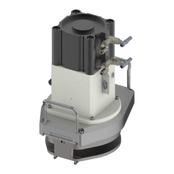
3. Operation VX TopCooler Part Number: 606325 Rev. A 3. Operation The TopCooler™ is directly controlled by the TMC through discrete inputs and outputs. The system software running on the TMC is also responsible for all interlocking and error handling. Figure 3-1: Drop-in TopCooler Annotation Description Poppet Assembly Cooling Chuck Assembly Cool Gas (Argon) Connection Digital Pressure Switch Copyright © 2023, Brooks Automation, Inc. - Page 19 Brooks Automation 3. Operation Part Number: 606325 Rev. A During normal operation the TopCooler remains closed until a wafer cool cycle is required. To cool a wafer, the Poppet is opened and a hot wafer is placed on the wafer shelf of the poppet. The poppet is closed, lowering the wafer onto the chill plate and a fixed quantity of gas is discharged into the closed cool chamber. After a fixed period of time, the gas is removed and the poppet is opened allowing removal of the cool wafer. Pressure sensing of the TopCooler is performed by the TMC monitoring the pressure switch, which indicates the pressure states inside of the cooler. This gauge has two outputs, LOW and HI, that indicate low and high pressure. There is no wafer sensor in this module. Also, there is no position indication on the valves so their position is verified by the system response as indicated by the pressure switch’s high and low programmed bits. The TopCooler poppet is located directly below the Lift Bar. To raise the poppet, the POPPET RAISE pneumatic control is asserted until the POPPET UP signal transitions from 0 to 1. To lower the poppet, the POPPET LOWER pneumatic control is asserted until the POPPET DOWN signal becomes true. Both operations should be subject to a time-out condition for error checking. The Charging Valve and the Backfill Initiation Valve are diaphragm valves which open when the signal is asserted and closed when the signal is released. The Rough Out Valve is a NW-16 poppet valve and tracks the single open/closed state. Refer to Figure 3-2. Copyright © 2023, Brooks Automation, Inc.
-
Page 20: Normal Cooling Cycle Operation
3. Operation VX TopCooler Normal Cooling Cycle Operation Part Number: 606325 Rev. A Figure 3-2: TopCooler Valve Operation Normal Cooling Cycle Operation Initial State The Charging Valve, Backfill Valve, and Poppet are closed. The Rough Out Valve is open. Load Wafer Sequence The Rough Out Valve is closed. The Poppet is opened. A wafer is placed on the poppet wafer shelf. The Poppet is closed, lowering the wafer onto the chill plate. Copyright © 2023, Brooks Automation, Inc. -
Page 21: Metering Of Gas Charge
A gas enters the feed line between the Charging Valve and the Backfill Valve creating a metered amount of the gas. The Charging Valve is closed. Pressure Gauge switch activates high output indicating charge is present. Cooling Cycle The Backfill Valve is opened. The metered amount of gas is discharged into the cool chamber. The chamber remains closed for a time determined by the user. Pressure Gauge switch returns to neutral state (no high or low outputs). Rough out The roughing line is opened. Gas is removed from the chamber. Pressure Gauge switch activates low output indicating chamber pumped down. Wafer Unload The Rough Out Valve is closed. The Backfill Valve is closed. The Poppet is opened. The wafer is removed. In normal operation, once a wafer is unloaded, a new wafer is immediately placed into the TopCooler and the poppet valve is closed. If, however, a new wafer is not placed into the chamber before the valve is closed, the roughing line is reopened to restore the TopCooler to the initial state. The Transport Chamber must be at vacuum to operate the TopCooler properly. If the Transport Chamber is changed to atmosphere and a wafer is in the TopCooler at vacuum, the Transport Chamber must be pumped down before attempting to open the TopCooler poppet or damage to the wafer will occur. Setting the Cooling Cycle Time The time that the chamber remains closed after the cooling cycle is complete is determined by the user. Copyright © 2023, Brooks Automation, Inc. -
Page 22: Selecting The Cooling Gas
Selecting the Cooling Gas Part Number: 606325 Rev. A The following information will assist in determining this time: Gas pressure (the inlet pressure must be 20 psig to maintain 20 Torr in the cooler) Temperature of wafer entering the TopCooler chamber The following variables must be defined and set by the user to create interlocks. Time period to cool a wafer Time period in which ramping must wait Time period in which roughing must wait Excessive temperature Pressure switch connected to HI/LOW input device monitors pressure to detect success or failure of all operations State of TopCooler (ramping, cooling, roughing, idle) Pressure state of TopCooler Selecting the Cooling Gas The TopCooler requires approximately 20 Torr of gas pressure. Argon is used with high vacuum systems due to its high pumping speed; Argon has a low thermal conductivity thereby making it less effective in heat conduction. Argon is also a noble gas and is invisible to chemical reactions. Copyright © 2023, Brooks Automation, Inc. -
Page 23: Maintenance And Repair
Part Number: 606325 Rev. A Preventative Maintenance 4. Maintenance and Repair Preventative Maintenance This chapter provides the schedule and procedures for routine preventive maintenance of the Micro Marathon Express. Brooks Automation recommends that the preventive maintenance procedures and schedule provided in this section be followed to extend the operating life of the system and to minimize unscheduled downtime. If additional procedures are required, they will be supplied, along with their maintenance schedules, by Brooks Automation. All Preventive Maintenance procedures and schedules provided here are made with the assumption that the system is operating in a clean, dry, inert environment. Any deviation from this basic environment will affect the scheduling of PM and may also require additional PM procedures. The user should adjust the Preventative Maintenance Schedule as appropriate to account for any deviations from this environment. Unauthorized Service Personal injury or damage to equipment may result if this robot is operated or serviced by unauthorized personnel. Only qualified personnel are allowed to transport, assemble, operate, or maintain the system . Properly qualified personnel are those who have received certified training and have the proper qualifications for their jobs. Read and understand the Safety chapter before performing any procedure. Due to the possible interference between a 200 mm wafer in the aligner and another on the robot’s arm, the robot should not be rotated or moved during maintenance if there is a 200 mm wafer in the Vacuum Aligner. Copyright © 2023, Brooks Automation, Inc. -
Page 24: Parts
Part Number: 606325 Rev. A Parts Brooks Automation can provide all parts required for Preventive Maintenance. For a list of these parts, contact Brooks Automation Customer Support. To obtain additional information about parts for preventive maintenance, contact the local Brooks sales representative, or call Brooks Automation Customer Support. See Contact Us for more information. TopCooler Cool Chuck Cleaning The Cool Chuck may be cleaned without removing it from the Transport Chamber. Required Tools Metric Hex Wrenches Maintenance Strategy The Cool Chuck is readily accessible after removing the drop-in Poppet Assembly. Turn off and disconnect all power, communications, and air connections as detailed in the Shut-down section of the system manual. Lockout / Tagout Working with energized equipment may cause sudden movement or electrical shock and may result in death or serious injury. All energy must be removed from the equipment per the facility’s Lockout/Tagout procedure before servicing. If local procedures are not available, follow the procedure for Lockout/Tagout in OSHA Standard 29CFR 1910.147. Copyright © 2023, Brooks Automation, Inc. - Page 25 Brooks Automation 4. Maintenance and Repair Part Number: 606325 Rev. A TopCooler Cool Chuck Cleaning The system may be used in an environment where hazardous materials are present, and surfaces may be contaminated by those materials. When this is the case, refer to the facility’s Material Safety Data Sheets for those materials to determine proper handling and follow the facility’s procedures to certify the environment is safe. Copyright © 2023, Brooks Automation, Inc.
- Page 26 4. Maintenance and Repair VX TopCooler TopCooler Cool Chuck Cleaning Part Number: 606325 Rev. A Maintenance Procedure Step Action Remove the Poppet Assembly by removing the (4) M8 screws securing the assembly to the Transport Chamber (refer to the "Vacuum Aligner Replacement" procedure in the system manual. The Cool Chuck is now accessible for cleaning. Use the "Pad Cleaning Procedure" in the system manual to thoroughly clean the plate. Do not allow alcohol to permeate the o-ring. It is recommended that the o-ring be removed before cleaning and replaced whenever the plate requires a rigorous cleaning. Refer to "TopCooler Chuck O-Ring Replacement" on page 36. Replace the Poppet Assembly and secure the hardware. Copyright © 2023, Brooks Automation, Inc.
-
Page 27: O-Ring Removal/Replacement/Cleaning
O-Ring Removal/Replacement/Cleaning All O-rings should be inspected periodically to ensure proper operation. Occasionally O-rings will need to be cleaned (if contaminated with particulates) or replaced (if damaged). Procedure Category Equipment is fully de-energized. Required Tools Brass or plastic pick Isopropyl Alcohol (100%) DI Water Maintenance Strategy The O-ring replacement procedure requires removal of the existing O-ring, inspection of the seal area, repair of the seal area if necessary, inspection of the O-ring, and replacement of the O-ring if necessary. Turn off and disconnect all power, communications, and air connections as detailed in the Shut- down section of the system manual. Lockout / Tagout Working with energized equipment may cause sudden movement or electrical shock and may result in death or serious injury. All energy must be removed from the equipment per the facility’s Lockout/Tagout procedure before servicing. If local procedures are not available, follow the procedure for Lockout/Tagout in OSHA Standard 29CFR 1910.147. Copyright © 2023, Brooks Automation, Inc. - Page 28 Using the pick, pry the old O-ring out of the O-ring groove starting at the plunge hole. Once a section of the O-ring is free of the groove, gently remove the rest of the O-ring by hand, being careful not to damage or scratch the O-ring or the seal area. NOTE: Use only a tool made of brass, plastic, or similar soft material. The O-ring groove is aluminum and EXTREMELY sensitive to ANY small scratches left in the surface. Copyright © 2023, Brooks Automation, Inc.
- Page 29 NOTE: Do not allow the O-ring to twist during installation. NOTE: Clean the O-ring by wiping down with DI water only. Do not use alcohol or other solvents, as they may cause the O-ring to become brittle. Reconnect all power, communications, and air connections, then re-energize the system following the "Power-up Sequence" in the system manual. Copyright © 2023, Brooks Automation, Inc.
-
Page 30: Topcooler Replacement
Metric Hex Wrenches Limits and Tolerances The facet-mounted TopCooler in the system is self aligning and requires no adjustments after installation. Replacement Strategy The TopCooler is removed in two subassemblies with four screws each. Turn off and disconnect all power, communications, and air connections as detailed in the Shut-down procedure of the system manual. Lockout / Tagout Working with energized equipment may cause sudden movement or electrical shock and may result in death or serious injury. All energy must be removed from the equipment per the facility’s Lockout/Tagout procedure before servicing. If local procedures are not available, follow the procedure for Lockout/Tagout in OSHA Standard 29CFR 1910.147. Unauthorized Service Personal injury or damage to equipment may result if this product is operated or serviced by unauthorized personnel. Only qualified personnel are allowed to transport, assemble, operate, or maintain the Product. Properly qualified personnel are those who have received certified training and have the proper qualifications for their jobs. Copyright © 2023, Brooks Automation, Inc. - Page 31 Brooks Automation 4. Maintenance and Repair Part Number: 606325 Rev. A TopCooler Replacement The system may be used in an environment where hazardous materials are present, and surfaces may be contaminated by those materials. When this is the case, refer to the facility’s Material Safety Data Sheets for those materials to determine proper handling and follow the facility’s procedures to certify the environment is safe. Removal Procedure Figure 4-1: Removing the TopCooler Step Action Critical Safety Step! Disconnect the two air connections and the communication connection at the Cable Fitting Mount on the top of the assembly. Disconnect the gas connections from the bottom of the assembly. Copyright © 2023, Brooks Automation, Inc.
- Page 32 Part Number: 606325 Rev. A Step Action Remove the Poppet Assembly from the chamber. Loosen the (4) M8 SHCS with split washers. For all TopCooler assemblies, grasp the Poppet Assembly using the attached handles as shown in Figure 4-1. Pull the assembly up and out of the Cooling Station slot on the Transport Chamber. Handle the assembly carefully to protect the o-ring from damage. Remove the Cooling Chuck Assembly from the chamber. Loosen the (4) M8 x 30 mm SHCS, M8 split, and M8 flat washers. Remove the Cooling Chuck Assembly by pulling assembly straight up and out of chamber. Handle carefully so as not to disturb the gauges located on the bottom of the assembly and the o- rings. Replacement Procedure Step Action Install the Cooling Chuck Assembly by placing assembly, gauges down, into the Cooling Station slot on the system Transport Chamber. Handle carefully so as not to disturb the o-rings. Secure the Cool Chuck assembly to the chamber with (4) M8 x 30 mm SHCS, M8 split, and M8 flat washers. Next, install the Poppet Assembly by placing onto the Cooling Station slot on the Transport Chamber. Handle assembly carefully to protect the o-ring from damage. Secure the Poppet Assembly to the chamber with (4) M8 SHCS with split washers. Connect the two air connections and the serial connection at the Cable Fitting Mount and the gas con- nections to the bottom assembly. Copyright © 2023, Brooks Automation, Inc.
-
Page 33: Topcooler Poppet Bellows Replacement
TopCooler Poppet Bellows Replacement The only moving seal within the TopCooler is the bellows weldment, which is a serviceable part. Required Tools Metric Hex Wrenches Replacement Strategy Turn off and disconnect all power, communications, and air connections as detailed in the Shut- down section of the system manual. Lockout / Tagout Working with energized equipment may cause sudden movement or electrical shock and may result in death or serious injury. All energy must be removed from the equipment per the facility’s Lockout/Tagout procedure before servicing. If local procedures are not available, follow the procedure for Lockout/Tagout in OSHA Standard 29CFR 1910.147. Unauthorized Service Personal injury or damage to equipment may result if this product is operated or serviced by unauthorized personnel. Only qualified personnel are allowed to transport, assemble, operate, or maintain the Product. Properly qualified personnel are those who have received certified training and have the proper qualifications for their jobs. Copyright © 2023, Brooks Automation, Inc. - Page 34 4. Maintenance and Repair VX TopCooler TopCooler Poppet Bellows Replacement Part Number: 606325 Rev. A The system may be used in an environment where hazardous materials are present, and surfaces may be contaminated by those materials. When this is the case, refer to the facility’s Material Safety Data Sheets for those materials to determine proper handling and follow the facility’s procedures to certify the environment is safe. Copyright © 2023, Brooks Automation, Inc.
- Page 35 Brooks Automation 4. Maintenance and Repair Part Number: 606325 Rev. A TopCooler Poppet Bellows Replacement Replacement Procedure Step Action Remove the Poppet Assembly. Refer to the procedure in the "Vacuum Aligner Replacement" pro- cedure in the system manual. Place the Poppet Assembly on a work bench. Remove the cover by loosening the Retaining Cover Knob. Remove the (4) M6 x 16 mm SBHS screws and remove the Hard Stop Plate. Disconnect the air. Disconnect the Up/Down sensor assemblies. Remove the M8 x 25 mm SHCS located in the Elastomer. Remove the (4) M6 x 30 mm SHCS and M6 split washers securing the Cylinder Mount Plate to the Mounting Flange. Lift the Cylinder Mounting Plate and the Air Cylinder and Plate will lift out. The bellows are now visible. Remove the (4) M6 x 12 mm SHCS with M6 split washers and remove the Bellows Weldment. Two o-rings are also associated with the replacement of the Bellows. Brooks recommends that these o-rings be replaced whenever the Bellows are replaced. Replace the Bellows Weldment by fully seating it into the Mounting Flange with the Bellows ring out. Replace all parts and hardware. Copyright © 2023, Brooks Automation, Inc.
-
Page 36: Topcooler Chuck O-Ring Replacement
Required Tools Metric Hex Wrenches Replacement Strategy The o-ring is readily replaced after removing the drop-in cartridge mechanism. The replacement time is less than 15 minutes. Turn off and disconnect all power, communications, and air connections as detailed in the Shut-down section of the system manual. Lockout / Tagout Working with energized equipment may cause sudden movement or electrical shock and may result in death or serious injury. All energy must be removed from the equipment per the facility’s Lockout/Tagout procedure before servicing. If local procedures are not available, follow the procedure for Lockout/Tagout in OSHA Standard 29CFR 1910.147. Unauthorized Service Personal injury or damage to equipment may result if this product is operated or serviced by unauthorized personnel. Only qualified personnel are allowed to transport, assemble, operate, or maintain the Product. Properly qualified personnel are those who have received certified training and have the proper qualifications for their jobs. Copyright © 2023, Brooks Automation, Inc. - Page 37 Brooks Automation 4. Maintenance and Repair Part Number: 606325 Rev. A TopCooler Chuck O-Ring Replacement The system may be used in an environment where hazardous materials are present, and surfaces may be contaminated by those materials. When this is the case, refer to the facility’s Material Safety Data Sheets for those materials to determine proper handling and follow the facility’s procedures to certify the environment is safe. Copyright © 2023, Brooks Automation, Inc.
- Page 38 4. Maintenance and Repair VX TopCooler TopCooler Chuck O-Ring Replacement Part Number: 606325 Rev. A Replacement Procedure Step Action Remove the Poppet Assembly. Refer to the procedure in the "Vacuum Aligner Replacement" pro- cedure in the system manual. The o-ring is now accessible for cleaning as shown in Figure 4-2. Use the "O-Ring Removal/Re- placement/Cleaning" on page 27 procedure to replace the o-ring. Do not apply any type of Vacuum Grease. Replace the Poppet Assembly and secure the hardware. Figure 4-2: Cool Chuck O-Ring Location Annotation Description Access Hole O-Ring Cool Chuck Copyright © 2023, Brooks Automation, Inc.
-
Page 39: Topcooler Poppet Speed Adjustment
TopCooler Poppet Speed Adjustment TopCooler Poppet Speed Adjustment The poppet is the moveable lid for the cool chamber in the TopCooler. Adjusting the speed ensures timely handoff and minimizes any wafer movement. Required Tools A computer running a terminal emulator or a dumb terminal Small, straight-slot screwdriver Stopwatch Adjustment Strategy Remove all material from the TopCooler Poppet and the Cool Tray before proceeding. Keep hands clear of the TopCooler Poppet and Cool Tray at all times. Lockout / Tagout Working with energized equipment may cause sudden movement or electrical shock and may result in death or serious injury. All energy must be removed from the equipment per the facility’s Lockout/Tagout procedure before servicing. If local procedures are not available, follow the procedure for Lockout/Tagout in OSHA Standard 29CFR 1910.147. Copyright © 2023, Brooks Automation, Inc. - Page 40 4. Maintenance and Repair VX TopCooler TopCooler Poppet Speed Adjustment Part Number: 606325 Rev. A Adjustment Procedure Step Action Close each Flow Control, shown in Figure 4-3, by turning the Flow Control Screw clockwise. Turn each Flow Control Screw two full revolutions counterclockwise (this serves as the initial flow set- ting). Open the Poppet valve using test software. Observe the time required to fully open the Poppet valve. The total cycle time should be 3 seconds. Adjust the Poppet speed as necessary to achieve a Poppet open cycle time of 3 seconds. Do this by turning the Close Flow Control Screw clockwise (speed decreasing) or counterclockwise (speed increasing). Retest the Poppet until achieving the desired Poppet speed. Close the Poppet using test software. Observe the time required to close the Poppet valve. The total time cycle time should be 3 seconds. Adjust the Poppet speed as necessary to achieve a Poppet close cycle time of 3 seconds. Do this by turning the Open Flow Control screw clockwise (speed decreasing) or counterclockwise (speed increasing). Retest the Poppet until achieving the desired Poppet speed. Copyright © 2023, Brooks Automation, Inc.
- Page 41 Brooks Automation 4. Maintenance and Repair Part Number: 606325 Rev. A TopCooler Poppet Speed Adjustment Figure 4-3: Poppet Speed Adjustments Annotation Description Open Adjustment Close Adjustment Copyright © 2023, Brooks Automation, Inc.
-
Page 42: Topcooler Poppet Open/Close Sensor Adjustment
Part Number: 606325 Rev. A Adjustment TopCooler Poppet Open/Close Sensor Adjustment The poppet is the moveable lid for the cool chamber in the TopCooler. Adjusting the open/close sensors ensures proper travel of the poppet. Required Tools A computer running a terminal emulator or a dumb terminal Small, straight-slot screwdriver Adjustment Strategy Remove all material from the TopCooler Poppet and the Cool Tray before proceeding. Keep hands clear of the TopCooler Poppet and Cool Tray at all times. Lockout / Tagout Working with energized equipment may cause sudden movement or electrical shock and may result in death or serious injury. All energy must be removed from the equipment per the facility’s Lockout/Tagout procedure before servicing. If local procedures are not available, follow the procedure for Lockout/Tagout in OSHA Standard 29CFR 1910.147. Copyright © 2023, Brooks Automation, Inc. - Page 43 Brooks Automation 4. Maintenance and Repair Part Number: 606325 Rev. A TopCooler Poppet Open/Close Sensor Adjustment Adjustment Procedure Step Action Locate the Poppet Valve Sensors on the side of the Poppet actuator. Loosen each sensor by turning its locking screw counterclockwise. Slide the Open sensor up until it reaches the end of travel. The LED should be green. Using test software, open the Poppet valve. Slowly slide the Open sensor down its track until the LED changes from green to yellow/red. Lock the Open sensor in place by turning the locking screw clockwise until snug. Slide the Close sensor down until it reaches the end of travel. The LED should be green. Using test software, close the Poppet valve. Slowly slide the Close sensor up its track until the LED changes from green to yellow/red. Lock the Close sensor in place by turning the locking screw clockwise until snug. Copyright © 2023, Brooks Automation, Inc.
-
Page 44: Troubleshooting
TopCooler leaks Bellows or o-ring leak "TopCooler Chuck O-Ring Replacement" on page 36 Poppet speed too high ( "1. Poppet Speed Too High") Wafer has moved after cool cycle Rough poppet motion ("2. Rough Poppet Motion") Process gas pressure too high ("8. Pressure Adjustment") Main chamber pressure rises during cool Leaky poppet o-ring ("3. Leaky Poppet O-Ring") cycle Cool chamber pressure does not rise during Insufficient process gas pressure ("8. Pressure Adjustment") cool cycle Leaky poppet o-ring ("3. Leaky Poppet O-Ring") Control board problem ( "4. Control Board Problems") Valve(s) not responding Other valve problems ("5. Other Causes for Inoperative Gas Valves") Insufficient process gas pressure ("8. Pressure Adjustment") Cooling water out of spec. ("6. Cooling Water Out of Spe- Wafer not cooling cification") Main chamber too hot ("7. Main Chamber Too Hot") Each possible cause in the chart is cross referenced to a numbered procedure in this section. After locating a problem in the chart, refer to the section listed for more detailed information. Copyright © 2023, Brooks Automation, Inc. - Page 45 Part Number: 606325 Rev. A Initial Troubleshooting 1. Poppet Speed Too High Check that the inlet air pressure is within the values specified in "Specifications" of the system manual before making any adjustments to the speed control valves. Adjust the speed of the poppet after verifying the pressure is within the range specified. 2. Rough Poppet Motion One cause of rough poppet motion is the use of a lubricated air supply. Small particles of oil, when passing through the restriction valves, momentarily restrict the air flow and cause a jerky motion. After switching to a dry air supply, the unit should be run through 10 to 20 up/down cycles to clear the oil from the system. 3. Leaky Poppet O-Ring Refer to "Maintenance and Repair" on page 23 of this manual and the system manual for lid o-ring cleaning and replacement information. 4. Control Board Problems Verify that all connections to the control board are secure and that the daughter board is properly seated on the control board. 5. Other Causes for Inoperative Gas Valves The operational chain for all gas valves is as follows: a. The control board sends power to a solenoid operated valve located on a panel of three valves on the opposite side of the unit. b. The solenoid operated valve pressurizes a thin air line which connects to a pneumatic actuator on top of the gas valve. c. The pneumatic actuator opens the gas valve. When diagnosing a malfunctioning valve, this sequence, combined with the electrical schematics and pneumatic diagrams supplied with this manual should allow the troubleshooter to quickly locate a defective component. 6. Cooling Water Out of Specification Verify that both the flow rate and temperature of the cooling water is within the range specified in "Specifications" of the system manual. Copyright © 2023, Brooks Automation, Inc.
- Page 46 5. Troubleshooting VX TopCooler Initial Troubleshooting Part Number: 606325 Rev. A 7. Main Chamber Too Hot If the main chamber is running at a very high temperature, the cooling parameters may have to be increased beyond the specified parameters. Contact Brooks Automation for assistance. 8. Pressure Adjustment Verify that the air or gas pressure is within the range specified in the "Specifications" section of the system manual. Copyright © 2023, Brooks Automation, Inc.
-
Page 47: Field Replaceable Units
Brooks Automation 6. Field Replaceable Units Part Number: 606325 Rev. A 6. Field Replaceable Units See the FRU list supplied with the System and associated FRU procedures. Copyright © 2023, Brooks Automation, Inc.
Need help?
Do you have a question about the VX TopCooler and is the answer not in the manual?
Questions and answers