Table of Contents
Advertisement
Quick Links
CONTENTS
Introduction .............................................. 1
Mount Controller ........................................ 2
Connections .............................................. 3
Terminals, Indicators and Switches ............... 4
Wiring Notes ............................................. 4
Sample Wiring ........................................... 5
Connect (Optional) Expansion Modules .......... 6
Connect (Optional) Ethernet Network ............ 6
Connect (Optional) Tier 2 Network(s) ............ 6
Connect Directly to PC (Optional) ................. 8
Select End Of Lines (EOL) ............................ 8
Connect Power .......................................... 9
Power and Communication Status ................10
CAN-590x EIO Network Isolation Bulbs .........11
Configure the Controller .............................12
Transferring Configuration Files ..................12
Configuring a Controller with HCM ...............12
Creating a Backup Panel File.......................13
Restoring with a Backup Panel File ..............14
KMDigital Network Configuration .................15
Ethernet Routing Table ...............................16
BACnet Configuration ................................17
Configure with Web Pages ..........................19
Operation ................................................31
Resetting the Controller .............................33
Important Notices .....................................34
Support ...................................................34
KMC Controls, 19476 Industrial Drive, New Paris, IN 46553
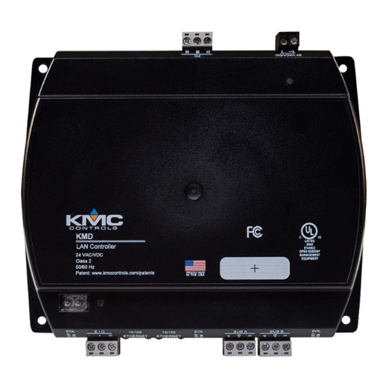
KMD-5290E LAN Controller
Installation and Operation Guide
INTRODUCTION
These are instructions for installing and operating a KMD-
5290E LAN Controller. Review this material in its entirety
before installing or operating the controller.
OVERVIEW
The LAN Controller may be operated in a stand alone
configuration or as part of a fully networked digital system.
The KMD-5290E uses Tier 1 networks with Ethernet hardware
to communicate with other LAN Controllers. The controller
also supports remote access to a Tier 1 network through a
dedicated serial port for direct connection to a PC. Unlike
legacy KMD LAN controllers, the KMD-5290E does not support
Tier 1 networking using EIA-485 connections.
The LAN Controller supports Tier 2 networks with two
dedicated RS-485 ports. Up to 32 KMD-5290E controllers can be
integrated into a single peer-to-peer network, each supporting
up to 124 nodes on each Tier 2 network.
The firmware in the controller uses Control Basic, a high-level,
easy-to-learn programming language. This programming
functionality is available from within KMC Connect and
TotalControl™ software.
/
877.444.5622
/
Fax: 574.831.5252
/
www.kmccontrols.com
Advertisement
Table of Contents

Related Manuals for KMC Controls KMDigital KMD-5290E


Summary of Contents for KMC Controls KMDigital KMD-5290E
-
Page 1: Table Of Contents
124 nodes on each Tier 2 network. The firmware in the controller uses Control Basic, a high-level, easy-to-learn programming language. This programming functionality is available from within KMC Connect and TotalControl™ software. KMC Controls, 19476 Industrial Drive, New Paris, IN 46553 877.444.5622 Fax: 574.831.5252 www.kmccontrols.com... -
Page 2: Mount Controller
MOUNT CONTROLLER Mount the controller inside a metal enclosure for RF shielding and physical protection. To mount the controller with screws on a flat surface, complete the steps in On a Flat Surface on page 2. To mount the controller on a 35 mm DIN rail (such as integrated in an HCO-1103 enclosure), complete the steps in On a DIN Rail on page... -
Page 3: Connections
4. Lower the controller against the DIN rail. 5. Push in the DIN latch to engage the rail. NOTE: To remove the controller, pull the DIN latch until it clicks once and then lift the controller off the DIN rail. CONNECTIONS The KMD-5290E LAN Controller may operate in either a stand-alone mode or connected by network to other controllers. -
Page 4: Terminals, Indicators And Switches
TERMINALS, INDICATORS AND SWITCHES Power Terminals RS-232 Serial Port Power/Status LED CAN-590x Expansion Module Network Status LED CAN-590x Expansion Module, Network Bulbs SubLAN A EOL Switch, Status LED SubLAN B EOL Switch, CAN-590X EIO EOL Switch Status LED CAN-590X IO Terminals SubLAN A and SubLAN B (Tier 2) Terminals Ethernet and IP Main Net (Tier 1) Terminals TERMINAL COLOR CODE... -
Page 5: Sample Wiring
SAMPLE WIRING (General Purpose Applications) Line Voltage NOTE: See the KMC Conquest™ Controller Application Guide for information about using VDC power. *NOTE: For a direct Tier 1 connection to a PC with an RS-232 serial port, Phase Neutral **Or use a KMD-5672 PC to Controller cable. -
Page 6: Connect (Optional) Expansion Modules
CONNECT (OPTIONAL) EXPANSION MODULES NOTE: Up to four CAN-5900 series expansion modules can be connected in series (daisy-chained) to a KMD-5290E LAN Controller for additional inputs and outputs. 1. Wire the gray EIO (Expansion Input Output) terminal block of the KMD-5290E series controller to the gray EIO terminal block of the CAN-5900 series expansion module. -
Page 7: Connect (Optional) Bacnet Ms/Tp Network
Do the following to wire the gray SUB A or SUB B terminal block of the KMD-5290E series controller to a Tier 2 network. 1. Connect the —A terminal to the negative wire of the cable. 2. Connect the +B terminal to the positive wire of the cable. 3. -
Page 8: Connect Directly To Pc (Optional)
CONNECT DIRECTLY TO PC (OPTIONAL) For a direct Tier 1 connection to a PC, attach a KMD-5672 cable between a USB port on the PC to the RS-232 serial port terminal block 4. Connect the TX terminal to the red wire of the cable. 5. -
Page 9: Connect Power
• If the controller is at either end of the SubLAN B network (only one wire under each terminal), turn that EOL switch to ON. CONNECT POWER NOTE: Follow all local regulations and wiring codes. Connect a 24 VAC, Class-2 transformer to the black power terminal block of the controller by doing the following. -
Page 10: Power And Communication Status
POWER AND COMMUNICATION STATUS The status LEDs indicate power connection and network communication. The descriptions below describe their activity during normal operation (at least 5 to 20 seconds after power-up/initialization or restart). NOTE: If both the green READY LED and the amber COMM LED remain OFF, check the power and cable connections to the controller. -
Page 11: Can-590X Eio Network Isolation Bulbs
Green ETHERNET LED The Ethernet status LEDs indicate network connection and communication speed. • The green Ethernet LED is ON when the controller is communicating with the network. • The green Ethernet LED is OFF when the (powered) controller is not communicating with the network. Amber ETHERNET LED •... -
Page 12: Configure The Controller
Before placing a controller into service, it must be initialized and addressed. See the following table for the most relevant KMC Controls tool for configuring, programming, and/or creating graphics for the controller. See the tools’ documents or Help systems for more information. -
Page 13: Creating A Backup Panel File
• USB to RS-232 serial adapter cable (for a Tier 1 serial connection to a PC with no RS-232 port) • Hardware Configuration Manager (software application, available for download from the KMC Controls Partner Portal at kmccontrols.com) Related Materials In addition to the material presented in this document, review and have available the following reference materials. -
Page 14: Restoring With A Backup Panel File
HCM will be begin saving the file as soon as Yes or No is clicked. RESTORING WITH A BACKUP PANEL FILE To restore a controller from a backup panel file, do the following: 1. Connect the computer running HCM to the controller and start HCM. 2. -
Page 15: Kmdigital Network Configuration
Hardware Configuration Manager Reference Guide. KMDIGITAL NETWORK CONFIGURATION The entries in the table HCM Configuration Screen Setup Fields are required for controller-to-controller communications on a KMC Controls Digital (KMD) network. Table 2 - HCM Configuration Screen Setup Fields Setting Description Address Enter the address that is assigned to the controller on the network. -
Page 16: Ethernet Routing Table
Use default (255.255.255.255) unless a router (gateway) is located between two Tier 1 controllers. The Gateway router IP address is supplied by the network system administrator. The MAC address can be found on the device web page. MAC addresses for KMC Controls products MAC Address begin with 00-D0-6F. -
Page 17: Bacnet Configuration
BACNET CONFIGURATION If the controller is configured for BACnet and connected to a BACnet network, the controller must be configured to communi- cate with the network. Table 4 - Tier 1 BACnet Settings Setting Description The device instance number as assigned by the BACnet system designer. Instance numbers are required, Instance must be unique among all devices on the internetwork and range from 0 to 4,194,303. - Page 18 Use BAC-SET, BAC-GET and BAC-RLQ in Control Basic to read and write other objects on other BACnet devices. KMC Controls recommends that all BACnet services have adequate error handling protocols within your control program. A sample Control Basic code segment is provided below to demonstrate reading the state of Binary Input 8 in a BACnet device with instance number 1.
-
Page 19: Configure With Web Pages
Before placing a controller into service, it must be initialized and addressed with KMC Hardware Configuration Manager (HCM) software appliction available on the KMC Controls website. Complete instructions for HCM are included in the Hardware Configuration Manager manual and the context-sensitive help system built into HCM. - Page 20 Device Window The Device window shows IP settings, KMD settings, CAN Module status, and BACnet settings. The Device window also configures the controller for the Local Area Network (LAN). Illustration1 - Device Window The IP Settings section displays the following parameters. •...
- Page 21 • KMD SubLAN B Baud — The baud rate of the SubLAN B port. NOTE: Navigate to the IP Table page to adjust panel addresses and IP settings. The CAN Modules section displays the status of up to four CAN expansion modules connnected through the EIO port. •...
- Page 22 • APDU Seg. Timeout — The Segment Timeout property indicates the time (in milliseconds) between retransmissions of an APDU segment. Parameters avaiable for a BACnet MS/TP connection (active through the SubLAN B port): Illustration 3 - BACnet Window - MS/TP •...
- Page 23 IP Table Configuration Window The IP Table window is used to view and adjust panel addresses and IP settings. The table shows up to 31 panels. Illustration 4 - IP Table Configuration Window Parameters available in this window are: • Panel Address — The address of the panel shown in the window. •...
- Page 24 Security Window The Security window sets user access to the controller. Illustration 5 - Security Window The KMD-5290E is configured with the following default user name and password. • User name: admin • Password: admin Note the following. • During configuration, the default admin/admin defaults should be changed to enhance security. •...
- Page 25 Firmware (Update) Window KMD-5290E firmware can be updated through the web browser after downloading the latest firmware from the KMC Controls website. Illustration 6 - Firmware Window To download from KMC and install the firmware file onto the computer: Log into the KMC Controls web site (www.kmccontrols.com) and download the latest zipped firmware file from the KMD controller’s product page.
- Page 26 Help Window NOTE: This feature will be available for the public release of the KMD-5290E. This is a connection to the KMC public web site with downloadable documentation and applications, such as the KMD-5290E LAN Controller Data Sheet, the Hardware Configuration Manager Reference Guide, and the Hardware Configuration Manager (HCM) software application.
- Page 27 Change a Computer’s IP Address Manually Introduction To change your computer’s IP address manually, follow the instructions (or the equivalent for your hardware and operating system) for Windows 10 (Settings) on page 27 Windows 7 (Control Panel) on page NOTE: Screens will look different in different versions of Microsoft Windows.
- Page 28 NOTE: Record the EXISTING settings of the Property dialog! NOTE: If Obtain an IP address automatically is selected, the IP address and Subnet mask of the computer are not shown. They can be seen, however, by running the ipconfig app from a command prompt. To run ipconfig, in the Search box, type cmd.
- Page 29 3. Click the local connection for the LAN. Depending on the computer and version of Windows, the exact name for the connection may be Ethernet, Local Area Connection, or something similar. 4. In the Local Area Connection (or similar) Status dialog, click Properties.
- Page 30 Troubleshooting • Check the network and connections. • Restart the controller. See Resetting the Controller on page • Review IP address and login information. • See the Communication Issues—Ethernet section in the KMC Conquest Controller Application Guide. Recovering an Unknown IP Address I f the network address of the controller is lost or unknown, the controller will respond to the default IP address for approximately the first 20 seconds after power is applied To discover an unknown IP address:...
-
Page 31: Operation
OPERATION This section provides general operating instructions for the KMD-5290E LAN Controller. Included are a description of the Isolation Bulbs, the LED status displays, connections, and instructions for resetting the controller. Carefully review this infor- mation as it applies to the task at hand. Applying Power The KMD-5290E LAN Controller is automatically powered when the power supply module is connected and plugged in. - Page 32 You can try restarting or resetting the controller. Erratic or Repeating Pattern Blink – If the LED is blinking, but not at a steady rate, the controller is indicating there is a problem. Contact KMC Controls for assistance. SYSTEM TIME KEEPING KMD LAN controllers feature real-time clocks.
-
Page 33: Resetting The Controller
RESETTING THE CONTROLLER Should the controller appear to lock up or stop operating, you must reset the controller to the factory default state. After the controller is reset, you must reload any existing panel files to restore normal operation. See Configuring a Controller with HCM on page 12 for additional details. -
Page 34: Important Notices
KMC Controls, Inc. makes no representations or warranties with respect to this manual. In no event shall KMC Controls, Inc. be liable for any damages, direct or incidental, arising out of or related to the use of this manual.
Need help?
Do you have a question about the KMDigital KMD-5290E and is the answer not in the manual?
Questions and answers