Advertisement
EX41941F Hardened PoE Switch
Installation Guide
1
Unpacking
Unpack the items. Your package should
include:
One EX41941F PoE switch
Power input terminal block
Wall and DIN-Rail mounting hardware
brackets
If items are missing or damaged, notify your
EtherWAN representative. Keep the carton
and packing material.
More information available at:
https://www.etherwan.com/us
For warranty information, visit:
https://www.etherwan.com/us/support/war
ranty-policy
2
Equipment Needed
Category 5e or better cable for RJ-45
ports
48VDC power supply with voltage
adjustable up to 56VDC and power output
to handle 120W PoE power budget.
3
Select a Location
DIN-rail installations: Attach the bracket
on the unit using the included screws and
then mount on a DIN-rail.
Wall installations: Attach the brackets on
the unit using the included screws and
then mount on a wall.
EX41941F
8/2/2022
Identify a power source within 6 feet (1.8
meters).
Choose a dry area with ambient
temperature between -40 and 75ºC (-40
and 167ºF).
Keep away from heat sources, sunlight,
warm air exhausts, hot-air vents, and
heaters.
Make sure there is adequate airflow.
4
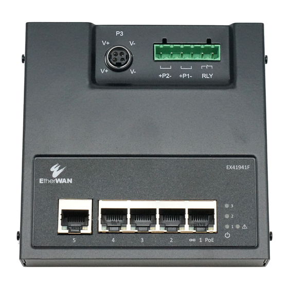
Connect to the Ports
The EX41941F has the following ports:
4 10/100/1000 Mbps PoE ports
1 10/100/1000 Mbps RJ-45 uplink port
10/100/1000BASE-T Ports
Ports 1 to 4 are gigabit copper ports that are
compliant with IEEE 802.3af/at PoE protocol,
with up to 30W power output per port. Port 5
is a gigabit copper port that can be utilized
for data uplink.
5
Connect Power
Terminal Block
Connect the unit to a suitable power supply
using appropriate wire, 18-24 AWG, rated for
105°C or higher.
Copyright 2022 EtherWAN Systems, Inc.
All Rights Reserved
Redundant power is supported. However,
only one power input is required to operate
the unit.
1. Connect power wires to the
appropriate P1+/- or P2+/- pins on
the terminal block.
2. Connect the grounding wire to the
ground screw.
3. Plug the terminal block into the
socket.
4. Alternatively, connect power 3 to an
external power adapter.
Relay Output Alarm
The switch provides relay output contacts for
redundant power. The relay output can be
connected to an alarm signaling device. The
current capacity is 1A@24VDC.
When dual power sources are connected,
the circuit is open.
When a single power source is connected
the circuit is closed.
The relay works with only power 1 and
power 2. It is not connected to power 3.
Page
1
Advertisement
Table of Contents

Related Manuals for EtherWAN EX41941F


Summary of Contents for EtherWAN EX41941F
- Page 1 4. Alternatively, connect power 3 to an Connect to the Ports and packing material. external power adapter. More information available at: The EX41941F has the following ports: https://www.etherwan.com/us 4 10/100/1000 Mbps PoE ports For warranty information, visit: 1 10/100/1000 Mbps RJ-45 uplink port ...
- Page 2 EX41941F Hardened PoE Switch Installation Guide Front Panel LEDs Notes LED Panel Layout Color Status Power Green ON = power detected OFF = power not detected Power Green ON = power detected OFF = power not detected Amber ON = One power source...
Need help?
Do you have a question about the EX41941F and is the answer not in the manual?
Questions and answers