Table of Contents
Advertisement
24-Port Web-Smart Ethernet Switch
FCC Statement
The FCC (Federal Communications Commission) restricts
the amount of radio frequency emission and radiation coming
from computer equipment.
The equipment introduced in this manual has been tested
and found to comply with the limits for a Class A digital
device pursuant to Part 15 of the FCC rules. These limits are
designed to provide reasonable protection against harmful
interference when the equipment is operated in a commercial
environment.
This equipment generates, uses, and can radiate radio
frequency energy, and if not installed and used in
accordance with the instruction manual, may cause harmful
interference to radio communications.
Operation of this equipment in a residential area is likely to
cause harmful interference in which case the user is required
to correct the interference at his/her own expense.
Any changes or modifications not expressly approved by the
manufacture would void the user's authority to operate the
equipment.
Trademarks
Product names mentioned in this manual may be trademarks
or registered trademarks of those products.
All trademarks or brand names mentioned are properties of
their respective companies.
User's Manual
1
Advertisement
Table of Contents

Related Manuals for EtherWAN EX1624W


Summary of Contents for EtherWAN EX1624W
-
Page 1: Fcc Statement
24-Port Web-Smart Ethernet Switch FCC Statement The FCC (Federal Communications Commission) restricts the amount of radio frequency emission and radiation coming from computer equipment. The equipment introduced in this manual has been tested and found to comply with the limits for a Class A digital device pursuant to Part 15 of the FCC rules. -
Page 2: Specifications
24-Port Web-Smart Ethernet Switch Preface This manual describes how to install and use the 24-Port Web- Smart Ethernet Switch. The TX ports of the switch introduced here auto-negotiates the presence of 10/100Mbps and full/half-duplex mode and auto-MDIX. In addition, it allows an optional 100Base- FX multi-mode or single-mode fiber module, enabling long distance connection. - Page 3 24-Port Web-Smart Ethernet Switch Table of Contents FCC S TATEMENT RADEMARKS REFACE ABLE OF ONTENTS RODUCT VERVIEW RONT ACKAGE ONTENTS RODUCT EATURES RONT ANEL ISPLAY HYSICAL ORTS Understanding Front Panel Design NSTALLATION ELECTING A ITE FOR THE QUIPMENT NSTALLATION AND LACEMENT NSTRUCTIONS Mounted to 19-inch standard rack...
-
Page 4: Table Of Contents
24-Port Web-Smart Ethernet Switch Port VLAN Trunking Save Configuration Load Default ECHNICAL PECIFICATIONS HYSICAL PECIFICATIONS ONNECTOR INOUTS RDERING NFORMATION User’s Manual... -
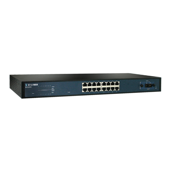
Page 5: Product Overview
24-Port Web-Smart Ethernet Switch Product Overview Front View Figure 1: 24-Port Web-Smart Ethernet Switch Package Contents When you unpack the product package, you shall find these items listed below. The 24-Port Switch One AC power cord User’s Manual Please inspect the contents, and report any apparent damage or missing items immediately to your authorized reseller. - Page 6 24-Port Web-Smart Ethernet Switch Product Features ♦ P 24 × 10/100M RJ-45 ROVIDES PORTS USING CONNECTORS ♦ A N OPTIONAL SINGLE PORT FIBER MODULE ALLOWS - 100B SC, ST, MT-RJ, VF-45 MULTI MODE FIBER WITH CONNECTOR - 100B SINGLE MODE FIBER WITH CONNECTOR ♦...
-
Page 7: Push Button
24-Port Web-Smart Ethernet Switch Front Panel Display The LED indicators on the front panel provide you with instant feedback on each port status, and help you monitor and troubleshoot the switch. Figure 2: Front Panel LEDs Power This LED comes on when the switch is properly connected to power and turned on. - Page 8 24-Port Web-Smart Ethernet Switch Physical Ports The 24-Port Switch has twenty-four 10/100Mbps ports using RJ-45 connectors and provides one slot for the optional single-port fiber module. The optional module allows fiber type (multi-mode or single-mode fiber) and connector (SC, ST, MT-RJ, VF-45, or LC) at user’s discretion.
- Page 9 24-Port Web-Smart Ethernet Switch Installation Selecting a Site for the Equipment As with any electric device, you should place the equipment where it will not be subjected to extreme temperatures, humidity, or electromagnetic interference. Specifically, the site you select should meet the following requirements: The ambient temperature should be between 0 to 45 degrees Celsius.
- Page 10 24-Port Web-Smart Ethernet Switch Installation and Placement Instructions OUNTED TO INCH STANDARD RACK Locate the accessories supplied in the product package. Use the rackmount brackets and screws to install the switch into any EIA 19” standard rack. Step 1: Attach the brackets to each side of the chassis. Step 2: Apply the screws to each side and secure them tightly.
- Page 11 24-Port Web-Smart Ethernet Switch Optional Fiber Module Installation Consult the following illustrations before installation. Step 1: Make sure the power is switched off. The module is not hot- swappable. It may cause electric shock or any possible damage to the switch if the power is not switched off.
- Page 12 24-Port Web-Smart Ethernet Switch Connecting to Power Locate the supplied AC power cord. Step 1: Connect the AC power cord to the receptacle at the back of the switch. Step 2: Attach the plug into a standard AC outlet with a voltage range from 100~240VAC.
- Page 13 24-Port Web-Smart Ethernet Switch ETWORK EGMENTATION The maximum segment distance between a node and a directly connected switch port on a 100Base-FX network is 100km using 10/125 (or 9/125) µm single-mode fiber optic cable. It is capable of a maximum span of 2km when 62.5/125 (or 50/125) µm multi- mode fiber optic cable is used.
-
Page 14: Switch Configuration
24-Port Web-Smart Ethernet Switch Switch Configuration Setting up Console Port Connection (Web- Based Browser Interface) The Ethernet Switch provides a browser interface that lets you configure and manage the Ethernet Switch from a Web browser (such as Microsoft Internet Explorer or Netscape Navigator) remotely. - Page 15 24-Port Web-Smart Ethernet Switch Main Menu YSTEM HANGE The System Change parameters can be displayed by clicking the System Change button in the left sub-menu. Switch Name: Type a switch name and replace the current switch name with a new one. (Please restart your Computer once the Switch Name is replaced User’s Manual...
- Page 16 24-Port Web-Smart Ethernet Switch and saved under “ Save Configuration “ by the new name). <Note> (Only “ a-z “, “A-Z”, “0-9”, “under line” & “Space” can be acceptable, totally can not exceed 16 characters). Password: Enter a user-defined password and change the factory default password.
-
Page 17: Port
24-Port Web-Smart Ethernet Switch Refresh: Click the Refresh On or Refresh Off button to or not to refresh back to the last saved settings of the ports. <Note> It is recommended to change the Refresh On button to Refresh Off while you change the settings of the ports. -
Page 18: Vlan
24-Port Web-Smart Ethernet Switch VLAN VLAN: Click and choose the ports to be added into the VLAN groups. Apply: Click the Apply button and apply the new settings of the VLAN groups. <Note> All Ports have to be selected to one of the VLAN Groups, those Port/Ports were not selected will be notified by the alarm message which shows “... -
Page 19: Trunking
24-Port Web-Smart Ethernet Switch RUNKING Trunking Group 1: Click and choose any four ports to be added into the Trunking Group 1. Trunking Group 2: Click and choose any four ports to be added into the Trunking Group 2. Apply: Click the Apply button and apply the new settings of the Trunking Groups. -
Page 20: Save Configuration
24-Port Web-Smart Ethernet Switch ONFIGURATION Click Save Configuration. Click the Ok or Cancel button to or not to save the configurations. <Note> The Cancel button will discard any data you have changed since the last "Save" operation. Without clicking Ok button, the switch does not save any changes you may have made. -
Page 21: Load Default
24-Port Web-Smart Ethernet Switch EFAULT Click Load Default. Click the Ok or Cancel button to or not to load the default settings. < Note > Once the Ok button is selected, all last saved Port, VLAN, and Trunking setting will revert back to the default settings. -
Page 22: Technical Specifications
24-Port Web-Smart Ethernet Switch Technical Specifications 24-Port Web-Smart Ethernet Switch Applicable IEEE 802.3 10Base-T Standards IEEE 802.3u 100Base-TX/FX Twenty-four ports for the 24-Port Switch Fixed Ports 100Base-FX multi-mode or single-mode module Optional 1-port Module Type Speed 100Base-TX/FX: 200Mbps for full-duplex; 100Mbps for half-duplex 10Base-T: 20Mbps for full-duplex;... -
Page 23: Physical Specifications
24-Port Web-Smart Ethernet Switch Physical Specifications 24-Port Web-Smart Ethernet Switch Dimensions 440mm (W) × 207mm (D) × 44mm (H) (17.32” (W) x 8.15” (D) x 1.73” H)) 19” rack mount size, 1U high Weight 2.8Kg (6.16lbs.) Power Input 100 ~ 240VAC, 50 ~ 60Hz 11.74W Max. -
Page 24: Connector Pinouts
24-Port Web-Smart Ethernet Switch Connector Pinouts Pin arrangement of RJ-45 connectors: Figure 5: RJ-45 Connector and Cable Pins The following table lists the pinout of 10/100Base-TX ports. Connector Pin-Out Regular Ports Uplink port Input Receive Data + Output Transmit Data + Input Receive Data - Output Transmit Data - Output Transmit Data +... -
Page 25: Ordering Information
24-Port Web-Smart Ethernet Switch Ordering Information 24 Fixed Ports Single-Port Module Cable Cable (/125µm) Distance Speed Distance Connector Connector 100Base-TX: 100m 100Base-FX (50µm or 62.5µm) Cat. 5 or better UTP/STP 100Base-FX (50µm or 62.5µm) RJ-45 100Base-FX (50µm or 62.5µm) MT-RJ 100Base-FX 10Base-T: (50µm or 62.5µm)
Need help?
Do you have a question about the EX1624W and is the answer not in the manual?
Questions and answers