Table of Contents
Advertisement
Quick Links
Advertisement
Table of Contents

Subscribe to Our Youtube Channel
Related Manuals for EtherWAN EX43000 series


Summary of Contents for EtherWAN EX43000 series
-
Page 1: Quick Start Guide
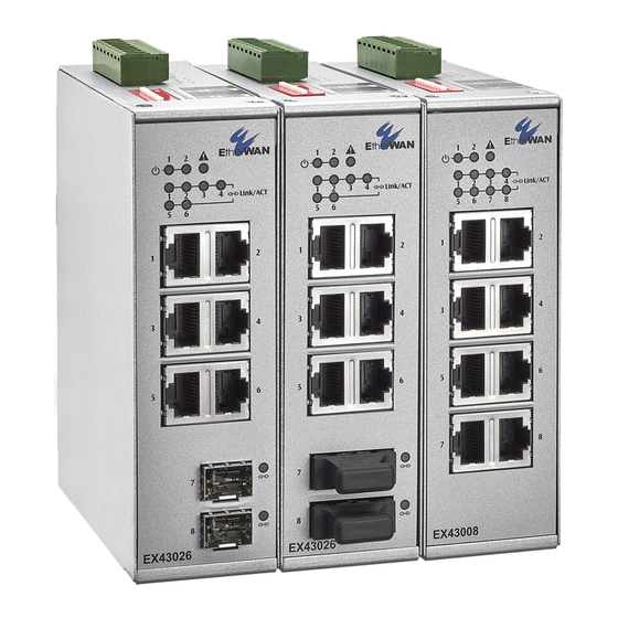
EX43000 series www.etherwan.com Quick Start Guide This quick start guide describes how to install and use the Industrial Ethernet Switch. This is the switch of choice for harsh environments constrained by space. Physical Description The Port Status LEDs... - Page 2 EX43000 series www.etherwan.com State Indication Steady Power on. Power off. Power 1, 2 (Green) Steady Relay starts alarm. Relay non-alarm. Fault (Red) Ports Steady A valid network connection established. Transmitting or receiving data. Blinking ACT stands for Activity. Link/ACT (Green)
-
Page 3: The Terminal Block And Power Inputs
EX43000 series www.etherwan.com The Terminal Block and Power Inputs Power Input Assignment 12~48VDC + Power 1 Power Ground - Terminal Block 12~48VDC + Power 2 Power Ground - Earth Ground Relay Output Rating 1A @ 250VAC DC Terminal Block Power Inputs: The DC Terminal Block power inputs can be used to power up this Switch. - Page 4 EX43000 series www.etherwan.com The 10/100Base-TX and 100Base-FX/BX Connectors 1. The 10/100Base-TX Connections The following lists the pinouts of 10/100Base-TX ports. Regular Ports Uplink port Output Transmit Data + Input Receive Data + Output Transmit Data - Input Receive Data -...
- Page 5 EX43000 series www.etherwan.com 4. The 100Base-FX/BX SFP Socket Connections The SFP socket for fiber optic expansion. Functional Description Meets EN61000-6-2 & EN61000-6-4 EMC Generic Standard Immunity for industrial environment. Supports 802.3/802.3u/802.3x. Auto-negotiation: 10/100Mbps, full/half-duplex. Auto MDI/MDIX. 100Base-FX: Multi mode/Single mode SC or ST type.
- Page 6 EX43000 series www.etherwan.com Dismantling: Pull out the lower edge and then remove the device from the DIN Rail.
-
Page 7: Preface
EX43000 series www.etherwan.com Preface A member of the growing family of rugged switches, this switch addresses a need for a smaller switch. This switch provides an affordable solution for rugged and outdoor environment, transportation road-side cabinet, industrial floor shop, multitenant dwellings or Fiber To The Home (FTTH) applications. -
Page 8: Table Of Contents
EX43000 series www.etherwan.com Table of Contents UICK TART UIDE HYSICAL ESCRIPTION The Port Status LEDs The Terminal Block and Power Inputs DIP Switch Settings The 10/100Base-TX and 100Base-FX/BX Connectors UNCTIONAL ESCRIPTION SSEMBLY TARTUP ISMANTLING REFACE ABLE OF ONTENTS RODUCT VERVIEW... -
Page 9: Product Overview
EX43000 series www.etherwan.com Product Overview Industrial Ethernet Switch Package Contents When you unpack the product package, you shall find the items listed below. Please inspect the contents, and report any apparent damage or missing items immediately to your authorized reseller. -
Page 10: Basic Features
EX43000 series www.etherwan.com Product Highlights Basic Features Meets EN61000-6-2 & EN61000-6-4 EMC Generic Standard Immunity for industrial environment. Supports 802.3/802.3u/802.3x. Auto-negotiation: 10/100Mbps, full/half-duplex. Auto MDI/MDIX. 100Base-FX: Multi mode/Single mode SC or ST type. 100Base-BX: WDM Multi mode/Single mode SC type. -
Page 11: Status Leds
EX43000 series www.etherwan.com Front Panel Display Status LEDs... - Page 12 EX43000 series www.etherwan.com State Indication POWER Switch is properly connected to power and Steady PWR1 turned on. PWR2 Switch is not connected to power and is (Green) turned off. FAULT Power redundant system failure occurred. Steady Port failure occurred (when port fault alarm dip switch is enabled).
-
Page 13: Installation
EX43000 series www.etherwan.com Installation This chapter gives step-by-step instructions about how to install the switch: Selecting a Site for the Switch As with any electric device, you should place the switch where it will not be subjected to extreme temperatures, humidity, or electromagnetic interference. - Page 14 EX43000 series www.etherwan.com DIN Rail Mounting Fix the DIN rail attachment plate to the back panel of the switch. Installation: Place the switch on the DIN rail from above using the slot. Push the front of the switch toward the mounting surface until it audibly snaps into place.
-
Page 15: Redundant Dc Terminal Block Power Inputs
EX43000 series www.etherwan.com Connecting to Power Redundant DC Terminal Block Power Inputs There are two pairs of power inputs can be used to power up this device. You need to have two power inputs connected to run the device, but the FAULT LED indicator will light up to remind that the power redundant system functions abnormal in case either PWR1 or PWR2 is dead. -
Page 16: Alarms For Power And Port Failure
EX43000 series www.etherwan.com Alarms for Power and Port Failure There are three pins on the terminal block are used for power failure detection. It provides the normally open or closed output when the power source is active. Use this as a dry contact application to send a signal for power failure detection. - Page 17 EX43000 series www.etherwan.com Connecting to Your Network Cable Type & Length It is necessary to follow the cable specifications below when connecting the switch to your network. Use appropriate cables that meet your speed and cabling requirements. Cable Specifications Speed...
- Page 18 EX43000 series www.etherwan.com Cabling Step 1: First, ensure the power of the switch and end devices are turned off. Always ensure that the power is off before any installation. <Note> Step 2: Prepare cable with corresponding connectors for each type of port in use.
-
Page 19: Specifications
EX43000 series www.etherwan.com Specifications Industrial Ethernet 10/100Base-TX auto-negotiating ports with RJ-45 connectors, 100Base-FX/BX fiber ports Switch or 100Base SFP sockets Applicable IEEE 802.3 10Base-T IEEE 802.3u 100Base-TX/FX Standards Store-and-Forward Switching Method Forwarding Rate 10Base-T: 10 / 20Mbps half / full-duplex... - Page 20 EX43000 series www.etherwan.com EN61000-4-5 (Surge Standards) EN61000-4-6 (Induced RFI Standards) EN61000-4-8 (Magnetic Field Standards) Environmental Test Compliance IEC60068-2-6 Fc (Vibration Resistance) IEC60068-2-27 Ea (Shock) FED STD 101C Method 5007.1 (Free fall w/ package) Tested with Cross Weight and Drop High standard table...
- Page 21 EX43000 series www.etherwan.com Appendix A – Connector Pinouts Pin arrangement of RJ-45 connectors: RJ-45 Connector and Cable Pins The following table lists the pinout of 10/100Base-TX ports. Regular Ports Uplink port Output Transmit Data + Input Receive Data + Output Transmit Data -...
Need help?
Do you have a question about the EX43000 series and is the answer not in the manual?
Questions and answers