
Related Manuals for Halma Ampac FastSense PLUS


Summary of Contents for Halma Ampac FastSense PLUS
- Page 1 Fire detection and evacuation solutions that save lives. High Sensitivity Detector Installation and Operation MAN 1502-9...
-
Page 2: Table Of Contents
Contents Page No Introduction ..........................1 Types of Detectors ........................2 Standard detector ......................2 Stand alone Command Module/ Command Module detector ..........2 Standard detector interior view ..................3 Stand-alone command module interior view..............4 Command module detector interior view ................5 Controls and Indicators...................... - Page 3 4.3.37 Command Module Scan for Detectors (CM, Yes / NO) ......... 27 Fault – Tolerant Communication Bus ( CM, Yes / No ) ........28 4.3.38 4.3.39 Command Module Communication Poll Time Out ( CM, Numeric ) ....28 4.3.40 Command Module Pager / GSM Phone Functions ( CM, Various ) ....
- Page 4 12.2 Input / Relay Card ......................68 Trouble shooting ........................69 13.1 Pressing RESET or ISOL. button has no effect .............. 69 13.2 Nuisance alarms occur too often..................69 13.3 Elevated smoke levels do not generate alarms .............. 69 13.4 Low mean output ......................
-
Page 5: Introduction
MAN 1502-9 Introduction FastSense PLUS is a highly sophisticated ‘next generation‘ High Sensitivity Aspirating Smoke Detection product that has been designed to ensure that installation and commissioning is as simple as possible, while optimising performance. FastSense PLUS incorporates a patented ‘artificial intelligence’ known as ClassiFire ® , which allows the detector to configure itself to optimum sensitivity, alarm thresholds and minimum nuisance alarms for any environment. -
Page 6: Types Of Detectors
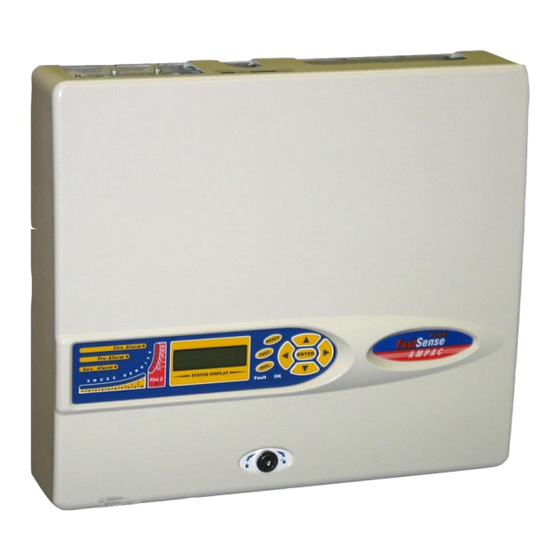
MAN 1502-9 Types of Detectors Standard detector The Standard Detector may be operated as a stand-alone unit, or may be part of a network of detectors centrally monitored by a Command Module (see section 2.2). It may be programmed via the front panel as in the version shown above. -
Page 7: Standard Detector Interior View
MAN 1502-9 Standard detector interior view WARNING Do not use aerolsol can synthetic smoke for testing this product Filter Replacement LASER CLASS 1 Ensure that filter is inserted with 'IN' position outwards. PRODUCT If filter is inserted incorrectly a fault will be generated. 1. -
Page 8: Stand-Alone Command Module Interior View
MAN 1502-9 Stand-alone command module interior view 1. Terminal block connections (see section 6.3.2) 2. 24VDC power supply connections (see section 6.4.2) 3. 500mA 5 x 20mm T-type protection fuse 4. Internal power supply (see section 6.4.3) 5. Stand-by batteries (see section 6.4.4) 6. -
Page 9: Command Module Detector Interior View
MAN 1502-9 Command module detector interior view WARNING Do not use aerolsol can synthetic smoke for testing this product Filter Replacement LASER CLASS 1 Ensure that filter is inserted with 'IN' position outwards. PRODUCT If filter is inserted incorrectly a fault will be generated. 1. -
Page 10: Controls And Indicators
MAN 1502-9 Controls and Indicators Standard detector Command Module detector Aux, Pre-Alarm, Fire 1 and Fire 2 indicators illuminate when the appropriate alarm level has been reached and the appropriate time delays have expired. On a stand-alone Command Module, the indicators signify an alarm condition from any detector on the communications loop. Smoke density indicators. -
Page 11: Types Of Display
MAN 1502-9 ENTER These buttons, also referred to in the text as menu buttons are used when programming the unit, which is pass code protected. See section 4, ‘Programming the unit‘ for more information. Pressing or when not in programming mode (the access code has NOT been entered) will scroll through the detectors event log. -
Page 12: Programming The Unit
MAN 1502-9 Programming the unit Engineering Access code It is not necessary to open the detector or Command Module case in order to program the unit. Programming of Standard Detectors or Command Modules may be carried out by using the front panel programming buttons. -
Page 13: Overview Of Programming Functions
MAN 1502-9 Overview of Programming Functions 4.2.1 Data entry All the editable programmable functions are accessible in the same way as described in section 4.1, using the arrow buttons to place the cursor under the field to be edited, the <<up arrow>> and <<down arrow>>... -
Page 14: Programming A Detector From A Command Module
MAN 1502-9 4.2.3 Programming a Detector from a Command Module A Command Module contains the full set of programmable instructions for detectors as well as those which apply to Command Modules. It can therefore be used to program any detector on the loop. When a function or sub-menu applies to individual detectors, rather than solely to a Command Module, the user is prompted to enter a detector or Command Module address number. -
Page 15: List Of Programmable Functions
MAN 1502-9 List of programmable functions As an example, each function will be recorded as follows Time and Date (All, Numeric) Setup menu Menu: Time and date Submenu: Time HH:MM Function(s): Date DD/MM/YYYY All means that the functions in the Time and Date submenu of the Command Module’s Setup menu are sent from the Command Module to all devices on the loop. -
Page 16: Time And Date ( All, Numeric )
MAN 1502-9 4.3.1 Time and date ( All, Numeric ) Time and Date (All, Numeric) Setup menu Menu: Time and date Submenu: Time HH:MM Function(s): Date DD/MM/YYYY All detectors are equipped with a battery backed-up Real Time Clock (RTC), which assigns times and dates to events stored in the event log (see section 4.3.41) and to chart recordings (see section 4.3.33). -
Page 17: Fire Alarm Levels (Detector, Numeric)
MAN 1502-9 4.3.2 Fire alarm levels (Detector, Numeric) Setup menu Menu: Alarm levels Submenu: Fire 2 level (1-25) Function(s): Fire 1 level (8-10) PreAlarm level (3-8) Aux level (1-25) Detectors incorporate two classes of alarm levels, relatively scaled and absolutely scaled. The relatively scaled alarm levels are specified relative to the mean of the smoke distribution of the normal working environment, set up during the unit’s 24-hour learning period. -
Page 18: Fire Alarm Time Delays (Detector Numeric)
MAN 1502-9 Detectors and Command Modules incorporate individual alarm relays for each alarm level (see section 6.3.1 and 6.3.2). The alarm signals are relayed to the Command Module via the RS485 bus, and also through the addressable bus terminals when an APIC card is fitted (see section 12.1). 4.3.3 Fire Alarm Time Delays (Detector Numeric) Setup menu... -
Page 19: Classifire Alarm Factor
MAN 1502-9 4.3.5 ClassiFire Alarm Factor Setup menu Menu: Alarm levels Submenu: Alarm factor (0-8) Function(s): This function statistically determines the maximum sensitivity of the detector’s relatively scaled fire alarms, based on the normal smoke distribution ascertained during the detector’s 24-hour learning period. -
Page 20: Hours Of Day/Night (Active/Inactive) Operation (Detector, Numeric)
MAN 1502-9 4.3.6 Hours of Day/Night (Active/Inactive) Operation (Detector, Numeric) Setup menu Menu: Alarm levels Submenu: Day start (0-23) Function(s): Night start (0-23) These values are the time, to the nearest hour, at which the detector will switch between day and night operation. -
Page 21: Automatic Fastlearn On Power Up (Detector, Yes / No)
MAN 1502-9 4.3.9 Automatic Fastlearn on Power Up (Detector, Yes / No) Setup menu Menu: Alarm levels Submenu: LDD enable Enter Yes/No Function(s): When this function is set to Yes, the detector will start a new FastLearn activity and reset the airflow fault parameters (see sections 4.3.32) whenever the detector is powered down and then powered up again. -
Page 22: Remote Day / Night Switching ( Detector, Yes / No )
MAN 1502-9 4.3.14 Remote Day / Night Switching ( Detector, Yes / No ) Setup menu Menu: Alarm actions Submenu: Remote day/hight Enter Yes/No Function(s): This is a remote function (see section 4.2.4). This function allows the detector to be manually toggled between day and night operation (see section 4.3.6) when the relevant activating terminals are shorted together. -
Page 23: Programmed Isolate (Any, Yes / No)
MAN 1502-9 4.3.17 Programmed Isolate (Any, Yes / No) Setup menu Menu: Alarm actions Submenu: Prog isolate Enter Yes/No Function(s): When set to Yes, the detector will not generate alarms and will not indicate a fault condition on any fire panel which is connected, e.g. for detector maintenance. When applied to a Command Module, it disables the Command Module fire and fault relays but does not disable any APIC (addressable bus) communications. -
Page 24: Reference Detector Enable ( Detector, Yes / No )
MAN 1502-9 necessary to set the Scan devices function on the Command Module to Yes (see section 4.3.37). Note: A Command Module does not amend the device text with unique identifiers when two detectors are set to the same device text setting, except in the default condition. This allows the same name or telephone number to be used for multiple areas. -
Page 25: Reference Desensitisation Delay (Detector, Numeric)
MAN 1502-9 4.3.23 Reference Desensitisation Delay (Detector, Numeric) Setup menu Menu: Reference Submenu: Back-off (0-99) Function(s): The reference Back-off figure reflects the fact that it may take time for smoke seen at the reference to reach the detector. The value entered into the Back-off function is the time delay in minutes before smoke seen at the reference arrives at the detector. -
Page 26: Power Saving Mode (Detector, Yes / No)
MAN 1502-9 4.3.25 Power Saving Mode (Detector, Yes / No) Set to No as this option is not available as a standard feature with the standard power supply. Setup menu Menu: Power checks Submenu: Power save Enter Yes/No Function(s): This function allows the detector to minimise electrical power consumption when operating from stand-by batteries. -
Page 27: Aspirator Speed (Detector, Numeric)
MAN 1502-9 4.3.28 Aspirator Speed (Detector, Numeric) Setup menu Menu: Air flow Submenu: Aspirator speed (1-16) Function(s): The value entered sets the aspirator in the detector to one of a range of predetermined speeds. The lower the number entered the lower the airflow rate and the lower the power consumption. The aspirator speed should be selected so that the smoke transport time from the farthest sampling hole from the detector is within any limits imposed by regulatory bodies (e.g., for the Loss Prevention Certification Board, this is 90 seconds). - Page 28 MAN 1502-9 Air flow Submenu: Flow low pipe 1 to Flow pipe flow 4 (0-99) Function(s): Flow high pipe 1 to Flow pipe flow 4 (0-99) Flow low is the flow sensor percentage reading below which the detector will generate a Low flow fault for the relevant sampling pipe.
-
Page 29: Detector Chart Log Recording Rate ( All, Numeric )
MAN 1502-9 4.3.33 Detector Chart Log recording Rate ( All, Numeric ) Setup menu Menu: Miscellaneous Submenu: Chart rate (0-19) Function(s): Detectors store a continuous record of percentage detector output and either laser chamber output as a percentage of full scale or the flow sensor percentage airflow rate. This chart log can be viewed on a PC running Ampac’s remote control software (see the Remote Software Guide) and saved to disk or sent by email for use as a diagnostic tool to show how the detector settings have varied over time. -
Page 30: User Defined Function Access Code ( Lcd< Numeric )
MAN 1502-9 4.3.34 User Defined Function Access Code ( LCD< Numeric ) Setup menu Menu: Miscellaneous Submenu: Access code (0-9999) Function(s): The access code is the four-digit number that has to be input before programmable functions can be edited (see section 4.1). The default access code is 0102, but for security purposes this can be changed to any four-digit number to prevent unauthorised access. -
Page 31: Command Module Scan For Detectors (Cm, Yes / No)
MAN 1502-9 4.3.37 Command Module Scan for Detectors (CM, Yes / NO) Setup menu Menu: Bus setup Submenu: Scan for devices Enter Yes/No Function(s): Number of detectors This function needs to be set to Yes after installation of a detector loop in order for the Command Module to scan the RS485 data bus for installed detectors. -
Page 32: Fault - Tolerant Communication Bus ( Cm, Yes / No )
MAN 1502-9 Note: The Bus scan function should only be used at installation or if making a permanent change to the detector network. If there are any errors in wiring leading to communications faults, these will be masked by a fresh bus scan, which will ignore any detector with which the Command Module is unable to communicate. -
Page 33: View Event Log (All, Entry)
MAN 1502-9 4.3.41 View Event Log (All, Entry) Setup menu Menu: Submenu: View event log Function(s): Detectors and Command Modules store a continuous record of alarm and fault events, power-ups, function changes and various other changes of state and aspects of the units with their time and date. -
Page 34: Communication Loop Errors ( Lcd, Entry )
MAN 1502-9 4.3.44 Communication Loop Errors ( LCD, Entry ) Diagnostics menu Menu: Loop errors Submenu: Function(s): This function displays the percentage error rate that the Command Module has detected on its communications loop. A loop error rate of 00.0% indicates that there are no communications problems. Frequent loop errors, i.e. -
Page 35: Detector Command Module Reset (All, Entry)
MAN 1502-9 Submenu: Watchdog count Function(s): The watchdog is a circuit built into detectors and Command Modules that resets the processor in the event of a failure to function properly. When this occurs, the detector will generate a fault indication and a Watchdog reset fault will be generated. -
Page 36: Exiting Programming Mode ( Lcd, Entry )
MAN 1502-9 The detector and Command Module Fault LEDs will only be extinguished if Latching faults are disabled (see section 4.3.13). If latching faults are enabled, pressing the enabled <<RESET>> button (see section 4.3.25) or selecting the Module Reset function (see section 4.3.45) will clear the fault indications. -
Page 37: 4.3.51 Menu Map
MAN 1502-9 4.3.51 Menu Map The following tables show all programmable functions for Detectors and Command Modules. Note that all detector functions and submenus are visible in the Command Module menus, but “Detectors only” functions will only appear if a valid detector address is entered. Entering “000” as the address in these functions will cause Bad detector to appear on the Command Module display. - Page 38 MAN 1502-9 Alarm levels submenu (Detectors only) Function Range of Default Section Comments values value Fire 2 level 1 – 25% obs/m 4.4.2 Absolute alarm level Fire 1 level 8-10 4.4.2 Relatively scaled alarm level PreAlarm level 4.4.2 Relatively scaled alarm level Aux level 2-10 4.4.2...
- Page 39 MAN 1502-9 Detector submenu (Detectors) Function Range of Default value Section Comments values Detector 001 - 127 4.4.18 As set on detector DIP switch address Device text 16 char. Ampac 4.4.19 Alphanumeric Detector submenu (Command Modules) Function Range of Default Section Comments values...
- Page 40 MAN 1502-9 Air flow submenu (Detectors only) Function Range of Default Section Comments values value Aspirator speed 1 (min) – 16 4.4.28 Changed value starts flow limit (max) setup Flow setup Yes / No 4.4.29 Changes to No when finished Sensor 1 enable Yes / No 4.4.30...
- Page 41 MAN 1502-9 Pager submenu (Command Modules only) Function Range of Default Section values value Call centre 16 chars 4.4.38 numeric zeros Password 16 chars 4.4.39 alphanumeric zeros Pager 16 chars 4.4.40 numeric zeros Page on fault Yes / No 4.4.41 Page on alarm Yes / No 4.4.42...
-
Page 42: 4.3.52 Error Messages
MAN 1502-9 4.3.52 Error messages Access timeout No front panel button has been pressed for 15 minutes Bad access code 1. An incorrect access code has been entered (see section 3.1), 2. 5 minutes has passed since the user was prompted for an access code and no code has been entered. - Page 43 MAN 1502-9 2. The Mains check function is enabled and the assigned remote input has not been connected to the mains fault outputs of an intelligent power supply The detector or Command Module’s Real Time Clock (RTC) has RTC fail failed.
-
Page 44: 4.3.53 Menu Map Summary
MAN 1502-9 4.3.53 Menu map summary Menu Submenu Item Section Time and Date Time HH:MM 4.3.1 Date DD/MM/YYYY Alarm levels Fire 2 level (1-25) 4.3.2 Fire 1 level (8-10) Pre Alarm level (3-8) Aux level (2-10) Fire 2 delay (0-99) 4.3.3 Fire 1 delay (0-60) Pre Alarm delay (0-60) - Page 45 MAN 1502-9 View event log 4.3.41 menu Diagnostics 4.3.42 Detector read 4.3.43 Loop errors 4.3.44 Dust separators 4.3.45 Diagno Relay test stic Pre Alarm + Fault menu Fire 1+Fault Fire 2+Fault 4.3.46 Fault Watchdog count 4.3.47 Reset 4.3.48 Isolate 4.3.49 Exit 4.3.50 Menu Map...
-
Page 46: Sampling Pipe Design
MAN 1502-9 Sampling Pipe Design Pipework Aspirating system design is inherently simple. It is often possible to achieve good system performance with very simple installations. There are however a few rules which must be adhered to, and these rules are equally applicable to all aspirating systems which operate on similar principles to FastSense PLUS. -
Page 47: Installation
MAN 1502-9 Installation General d. Sampling pipes must have capped ends. The end cap should be drilled with a sampling hole normally between 4 or 5mm diameter and free from burrs. Sampling holes should normally be 3- 4mm diameter or as calculated by PipeCalculator and free from burrs. Each pipe run should not have more than 25 holes. - Page 48 MAN 1502-9 The wall will also need to be suitably prepared to allow the mounting plate to sit flush against the wall. The sampling and exhaust pipes must also extend out of the wall sufficiently to tightly engage in the pipe entries on the rear of the detector as shown. A good starting point would be 25mm of pipe extending past the back plate.
-
Page 49: Sampling Pipes
MAN 1502-9 6.2.1 Sampling Pipes Pipes should be prepared as indicated in section 4.1. FastSense PLUS detectors have five pipe inlets. As viewed from the front of the detector, these run (from left to right) Exhaust – Sampling pipe 1 - Sampling pipe 2 - Sampling pipe 3 - Sampling pipe 4. Each sampling pipe inlet on the detector is supplied with a sampling port bung fitted to avoid ingress of dust and detritus inside the detector. -
Page 50: Removal And Replacement Of The Detector Front Cover
MAN 1502-9 6.2.3 Removal and replacement of the detector front cover To remove the front cover, unlock it using the key provided (turn anticlockwise). The bottom of the front cover may then be lifted away from the detector chassis until the top of the cover disengages from the retaining rails at the top of the chassis. -
Page 51: Electrical Installation
MAN 1502-9 Electrical installation 6.3.1 Detector terminal block connections All electrical (power and signal) connections should be made to the green terminal block inside the detector. Power cables should be screened and of sufficient current carrying capacity. Signal cable should be 120Ω screened twisted pair such as Belden 9841 0.22mm². Power and signal cables should enter the detector via metal cable glands. -
Page 52: Command Module Terminal Block Connections
MAN 1502-9 6.3.2 Command Module terminal block connections All electrical (power and signal) connections should be made to the green terminal block inside the detector. Power cables should be screened and of sufficient current carrying capacity. Signal cable should be 120Ω screened twisted pair such as Belden 9841 0.22mm². Power and signal cables should enter the detector via metal cable glands. -
Page 53: Connecting Power Cables
MAN 1502-9 6.3.3 Connecting power cables For the system to meet full EMC compliance requirements, the following precautions should be taken: Screened power cable should be used. The earth wire of power cables should be connected to the detector EARTH terminal, and this in turn connected to an earth stud on the detector chassis. -
Page 54: External Power Supply
MAN 1502-9 6.4.1 External power supply The 302-589 ( 2 Amp ), 302 543 ( 6 Amp ) power supplies provide the 27VDC to charge batteries and supply power to the FastSense Command Module or FastSense Detectors. PSU STATUS POWER ON BATTERY HIGH BATTERY LOW BATTERY FAIL... -
Page 55: Backup Batteries
MAN 1502-9 6.4.2 Backup batteries The power supplies fitted with 2 x 12V, backup batteries to give up to 24 hours’ operation in the event of mains power failure. The battery charger can recharge the batteries to a minimum of 80% capacity within 24 hours of mains reconnection to comply with AS4428 part 5 or NZ4512. -
Page 56: External Communication
MAN 1502-9 External Communication BMS protocols on the FastSense PLUS Command Module The Command Module of the FastSense PLUS has a second RS232 port that can be used to send messages to a pager or compatible GSM phone using a modem or to enable connection to a Building Management System (BMS). -
Page 57: Paging From The Command Module
MAN 1502-9 7.1.3 Paging from the Command Module The FastSense PLUS Command Module has the facility to send text messages to alphanumeric pagers or SMS messages to some mobile phones. In order to send messages to a pager or similar device a modem must be plugged into the RS232TX and RS232RX terminals of the Command Module using a suitable cable. -
Page 58: Event Log
MAN 1502-9 Event log An event is defined as operation of any of the front panel controls (when enabled), a signal received from a remote source (e.g. the master controller or PC), a detector level exceeding the Aux., Pre- Alarm, Fire 1 or Fire 2 thresholds or certain commands sent from the remote software or SenseNET. -
Page 59: Interfacing
MAN 1502-9 Interfacing Because of the flexible nature of the FastSense PLUS detector and the many possible configurations, there are many options for interfacing the detectors to the Fire Panel. These include many third party interfaces available from various manufacturers. Because of this, it is not possible to give a complete list of all interfacing methods but the following pages will give details of the most common methods that are likely to be used. -
Page 60: Address Table
MAN 1502-9 9.1.1 Address table Addresses chosen for detectors do not have to be consecutive or in a given order as long as they are all different. Page 56... -
Page 61: Connecting A Detector Network To A Command Module
MAN 1502-9 Connecting a detector network to a command module 120 ohm screened twisted pair such as Belden 9841 24 AWG should be used for all loop connections. The RS485 A and B wires should be taken through a ferrite (supplied) with a single loop illustrated for the power wires in section 6.3.3. -
Page 62: Connecting A Command Module To An Addressable Fire Panel
MAN 1502-9 Connecting a Command Module to an addressable Fire Panel When a Command Module is being used to manage one or more detectors (the maximum limit is 127) then an Addressable Protocol Interface Card (APIC) may be used to decode detector status information in the Command Module and relay to the Fire Panel via the Addressable Bus 1 and Bus 2 terminal block connections (see section 5.3.2 ‘Command Module terminal block connections’... -
Page 63: Connecting A Single Fastsense Plus To An Addressable Fire Panel
MAN 1502-9 Connecting a single FastSense PLUS to an addressable Fire Panel An APIC may be used to decode detector status information and relay this to the Fire Panel via the Addressable Bus 1 and Bus 2 terminal block connections (see section 5.3.1 ‘Detector terminal block connections’... -
Page 64: Commissioning
MAN 1502-9 Commissioning 10.1 Commissioning checklist IMPORTANT NOTE Before commissioning the detector the local standards of aspirating detection systems must be consulted. These standards differ widely throughout the world and specific advice for the market in one country may not be applicable to another. Commissioning strategy will initially depend upon the environment in which the detector is installed. -
Page 65: 11 Maintenance
MAN 1502-9 11 Maintenance FastSense PLUS is a very low maintenance detection system. If required, external cleaning of the unit should be performed using a damp (not wet) cloth. Do not use solvents as these may mar the display bezel. The only part that may require field replacement during servicing is the dust separator assembly. - Page 66 MAN 1502-9 A suggested series of checks for periodic planned maintenance is given as follows; At three month (Quarterly) intervals: 1. Isolate the detector from the main fire panel. 2. Inspect the front cover for signs of physical damage, moisture ingress and ensure that the detector is securely mounted to the wall.
- Page 67 MAN 1502-9 At six monthly intervals: The procedures listed below should be carried out in addition to those listed in the Quarterly inspection. 1. Isolate detector at main fire panel to avoid a fault condition being reported 2. Check physical condition of batteries, test batteries to ensure that they hold sufficient charge to provide the required standby time 3.
-
Page 68: Optional Extras
MAN 1502-9 Optional Extras Addressable Protocol Interface Card (APIC’s) 12.1 General An Addressable Protocol Interface Card (APIC) can be fitted to an individual FastSense detector or a command module to decode detector information and to relay this information to and from an FACP. That is to say an APIC can be used as a single loop interface unit, or when used with a command module one APIC can be used to communicate data to and from up to 126 FastSense units (via the one APIC module.) - Page 69 MAN 1502-9 Note: When first ordering APIC cards, it is advisable to check with Ampac that an APIC with the required communication protocol is available before ordering. Address settings There are two address switches on the APIC, SW1 and 2. If only a single loop address is required, both switches are set to the same address, e.g if the sensor address is 4 then both SW1 and SW2 are both set to address 4.
- Page 70 MAN 1502-9 Example 2 There are 7 detectors fitted to an addressable loop. The next device on the loop is an APIC connected to a command module which has a Sensenet communications loop fitted with 5 FastSense units connected. The first APIC address (SW1) switch is set 8 and the second address switch (SW2) is set to address 12.
- Page 71 MAN 1502-9 Reporting to FireFinder. Fastsense Plus will report the following to FireFinder. Status Count Fault Normal Aux alarm Pre-Alarm Fire 1 Fire 2 Flow/separator fault 1 Mains/battery fault Detector Isolated The three output bits from the fire panel are monitored as inputs 1 to 3 or 4 to 6 depending upon the detector type as follows: It is possible to reset, isolate and activate Classifire Override (Remote Day / Night settings in ConfigManager) on the FastSense Plus from the FireFinder...
-
Page 72: Input / Relay Card
MAN 1502-9 12.2 Input / Relay Card The main use of this card is to provide three extra remote inputs, which can be used with ClassiFire override (see section 4.3.4), remote day / night switching (section 4.3.14), remote reset (section 4.3.15) remote isolate (section 4.3.16), battery monitoring (section 4.3.26) and mains power monitoring (section 4.3.27). -
Page 73: Trouble Shooting
MAN 1502-9 Trouble shooting 13.1 Pressing RESET or ISOL. button has no effect ➢ Check that the controls have been enabled. These functions are disabled by default. See section 3.4.24 13.2 Nuisance alarms occur too often ➢ Check that the ClassiFire alarm factor setting is appropriate for the normal working environment of the protected area. -
Page 74: 13.6.1 "Low Flow" Error Messages
MAN 1502-9 13.6.1 "Low flow" error messages. ➢ Check that the pipe giving the error is not blocked. ➢ Check that, if the pipe is unused, the flow sensor for this pipe has been disabled (see section 3.4.30). ➢ Check that the low flow fault threshold is not set too high (see section 3.4.30). ➢... -
Page 75: Garbled Characters On The Lcd
MAN 1502-9 13.10 Garbled Characters on the LCD The detector or Command Module shows garbled characters on the LCD screen or does not accept function updates. This may be because the contents of the detector’s or Command Module’s battery backed-up Random Access Memory (RAM) has become corrupted. -
Page 76: Error Messages
MAN 1502-9 Error messages The FastSense PLUS text display can provide a wide range of information about the detector. A list of error messages follows with a brief explanation of their meanings. Separator renew : The dust separator requires replacement. See section 10, ‘Maintenance‘ Separator change : The dust separator is missing or improperly fitted. -
Page 77: Do's And Don'ts
MAN 1502-9 Do’s and Don’ts Ensure that the ClassiFire alarm factor is appropriately set. Ensure that reference detectors are correctly connected before powering up by use of cable identifiers or electrical continuity checks. Incorrect connection could damage the detector. Ensure that cable of an appropriate approved type is used for interconnection. Place sampling points so that the detector will be able to detect smoke at the earliest opportunity. -
Page 78: Fastsense Plus Specification
MAN 1502-9 FastSense PLUS specification SELV rating Class III or AS/NZS3260:93 Supply Voltage 21.6V - 26.4V DC PSU Type: conforming to AS4428 part 5 or NZ4512 Size (mm) 427W x 372H x 95D Weight 5.2kg (Detector) 5.3kg (Command Module Detector) 6.2kg (Stand-alone Command Module) 10.1kg (Stand-alone Command Module + batteries) Operating temperature range... - Page 79 NOTES: UNCONTROLLED DOCUMENT NOTE: Due to AMPAC’s commitment to continuous improvement specifications may change without notice.
Need help?
Do you have a question about the Ampac FastSense PLUS and is the answer not in the manual?
Questions and answers