
Related Manuals for Halma Ampac FastSense 25


Summary of Contents for Halma Ampac FastSense 25
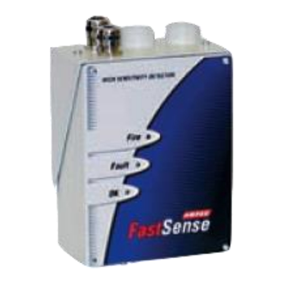
- Page 1 Fire detection and evacuation solutions that save lives. FastSense High Sensitivity Detector Installation and Operation MAN 2285-9...
-
Page 2: Table Of Contents
MAN2285-9 Table of Contents Section Page No Introduction Indicators Inside the Detector Interior View Detector terminal block connections Programming the Detector Introduction Time and date Alarm levels Alarm delays ClassiFire override Alarm factor LDD enable FastLearn enable Auto FastLearn enable 4.10 ClassiFire 3D 4.11... - Page 3 MAN2285-9 Load / save function settings Sampling Pipe Design Pipework Installation Docking station 7.1.1 Mechanical installation 7.1.2 Electrical installation Error! Bookmark not defined. 7.1.3 Power supply connections Error! Bookmark not defined. 7.1.4 Signal connections 7.1.5 Connecting ancillary cables Final installation 7.2.1 Connecting ancillary cables Interfacing...
-
Page 4: Introduction
MAN2285-9 1 Introduction FastSense 25 incorporates a patented ‘artificial intelligence‘ known as ClassiFire ® , which allows the detector to configure itself to optimum sensitivity, alarm thresholds and minimum nuisance alarms for any environment. ClassiFire intelligence also monitors the detector chamber and dust separator for contamination, continually adjusting the appropriate operating parameters to counteract the negative effects of such contamination. -
Page 5: Indicators
MAN2285-9 equipment in accordance with these instructions. 2 Indicators 1. Fire indicator illuminates when the alarm level has been reached and the appropriate time delays have expired. 2. Fault. Illuminates when the unit has a fault, and a fault signal is being sent to the fire alarm panel. -
Page 6: Inside The Detector
MAN2285-9 Inside the Detector 3.1 Interior View DOCKING STATION PIPE ADAPTERS CABLING IN Direction of flow DIRECTION OF FLOW DETECTOR 1. Removable terminal blocks 2. Filter (see Section 11) 3. Addressable bus interface card (APIC) port mounting (see Section 8) 4. -
Page 7: Detector Terminal Block Connections
MAN2285-9 3.2 Detector terminal block connections 1. Normally closed FAULT relay contacts 2. Normally open FIRE relay contacts ( See note ) 3. APIC addressable bus connections for use in conjunction with 4. interface card (see Sections 7 and 8) 5. -
Page 8: Programming The Detector
MAN2285-9 Product for New Zealand is modified to accommodate “Normal closed FIRE contacts” to Note: meet the requirements of NZS4512 – 2003. 4 Programming the Detector 4.1 Introduction FastSense 25 may be programmed from a PC when connected to the detector via a standard 9-pin serial lead connected to the serial port of the computer and the 9 way socket at the base of the detector (see section 8.4, ‘Connecting to a PC’). - Page 9 MAN2285-9 internal/calender/clock is backed up with a rechargeable battery. Later adjustments to the clock setting should not exceed ± 70 minutes unless a FastLearn is initiated Page 6...
-
Page 10: Alarm Levels
MAN2285-9 4.3 Alarm levels Alarm levels and delays tab, Level subgroup The value set in the Fire, PreAlarm and Aux functions in the Level subgroup is the relatively scaled bargraph level at which the appropriate alarm is initiated on the detector. The Fire 2 level assigns an absolutely scaled alarm level in % obs/m. -
Page 11: Ldd Enable
MAN2285-9 4.7 LDD enable Alarm levels and delays tab When this function is ticked, Laser Dust Discrimination (LDD™) increases the response time of the detector slightly, whilst greatly reducing the likelihood of nuisance alarms due to dust ingress. LDD may be disabled in very clean rooms for a slightly faster response to smoke by unticking the box. - Page 12 MAN2285-9 ambient smoke levels. For this reason, the detector should not be left in Demo mode for normal use when connected to a fire panel. Page 9...
-
Page 13: Day Start / Night Start
MAN2285-9 4.12 Day start / Night start Day/Night switching tab These values are the times to the nearest hour at which the day/night switching is desired to take place on the detector. Entries are made in 24-hour format, e.g. 19 for 7pm. Day and night switching is intended so that the detector may automatically select a different sensitivity when the protected area is unoccupied and fewer contaminants are being produced. -
Page 14: Device Type
MAN2285-9 4.19 Device type Device information tab This function is for display purposes only. It shows any special designation for the unit, which will normally be FastSense 25. 4.20 Firmware version Device information tab This function is for display purposes only. It shows the version number of the fitted firmware chip. 4.21 Run-time hours Device information tab This function is for display purposes only. -
Page 15: Flow High Limit
MAN2285-9 This function is for display purposes only, and shows a value corresponding to the cur-rent airflow through the detector. 4.29 Flow high limit Flow monitoring tab This value is the level above which airflow needs to increase to trigger a fault indication (which may indicate a loose or damaged inlet pipe). -
Page 16: Separator Condition
MAN2285-9 flow recording 10 minutes 100 minutes flow recording 20 minutes 200 minutes flow recording 50 minutes 500 minutes In the above table the greyed section indicates flow rate recording while the white section indicates detector and alarm level recording. At the slowest recording rate, one month of data can be recorded. -
Page 17: Other Remote Software Features
MAN2285-9 5 Other remote software features 5.1 Reset If latching alarms (see Section 4.16) or latching faults (see Section 4.17) are enabled, the relevant alarm or fault warnings will remain on the detector front panel LED’s and controlling unit until a reset is performed. If using SenseNET software, individual detec-tors can be reset (refer to the SenseNET User Guide for details). -
Page 18: Chart Recording
MAN2285-9 Detector sensitivity is based on the fast histogram during FastLearn and is thereafter based on the currently active slow histogram. However, although the positions of the alarm flags are based on the slow histogram, sudden changes in smoke density are picked up by the fast histogram so that early warning is given. Sensitivity: The current absolute sensitivity of the detector in percentage obscuration per metre (% obs/m) Mean: The current mean value of smoke density, taken from the currently “active”... - Page 19 MAN2285-9 chart recording to be loaded. Chart recording files have the extension “.rcw”. Page 16...
-
Page 20: Load / Save Function Settings
MAN2285-9 5.3 Load / save function settings Where a custom set of programmable function settings is commonly used, these may conveniently be saved to or loaded from disk. To open a detector function settings (.dfs) file, select the menu options “File Open” or click on the symbol indicated below. -
Page 21: Sampling Pipe Design
MAN2285-9 6 Sampling Pipe Design Above ceiling sampling with exposed detector Simple designs with short sampling pipes produce the best results. Complex sampling pipe runs should be avoided with the FastSense 25 detector. The use of ‘T’ branch-pipes is not recommended. Always locate the sampling points in positions to which smoke may reasonably be expected to travel. -
Page 22: Pipework
MAN2285-9 Above ceiling sampling with detector mounted in ceiling void Sampling Hole Sampling Pipe FastSense 25 False Ceiling Always locate the sampling points in a position to which smoke may reasonably be expected to travel. This may sound obvious, but, for example, do not expect ceiling mounted sampling points to operate satisfactorily if air flow prevents the cool smoke from an incipient fire from reaching ceiling level. -
Page 23: Installation
MAN2285-9 7 Installation Before installing the detector the local standards for installation of aspirating detection systems must be consulted as these standards differ throughout the world. Specific advice for one country may not be applicable to another. The following is a brief set of guidelines on installing detectors. The detector will normally be mounted at a level where there is easy access to the unit for configuration and programming. -
Page 24: Docking Station
MAN2285-9 7.1 Docking station The basic principle behind installation of the FastSense 25 is that all wiring and pipework is installed using a docking station. This is a convenient feature which means that the detector can be dismounted or replaced without disturbing any wiring or installed pipework. -
Page 25: Mechanical Installation
MAN2285-9 Fitting the pipe adapter 7.1.1 Mechanical installation The docking station is connected to the installed sampling pipework and fixed to the wall or mounting surface using 3 off screws of a type appropriate to the mounting surface. Ensure that the sampling and/or exhaust pipes are securely seated in the pipe ports before fixing. -
Page 26: Signal Connections
MAN2285-9 7.1.4 Signal connections To connect the signal wire, lead a suitable wire type through the second cable gland and tighten it into position with about 35mm of cable from the bottom of the cable gland. Remove either the three-way terminal block next to the power supply socket if connecting the detector to a SenseNET system, or the four-way “Bus”... -
Page 27: Connecting Ancillary Cables
MAN2285-9 7.1.5 Connecting ancillary cables Cable Gland Cable Screen Cabling Plug FIRE FAULT Ferrite Connect cabling to " FIRE " For the system to meet full EMC compliance requirements ensure the wiring to the “FIRE“ terminals Note: is looped through the supplied ferrite ring. 7.2 Final installation 7.2.1 Connecting ancillary cables Once the power and signal connections are made slide the detector body up into the docking station and fasten... -
Page 28: Interfacing
MAN2285-9 8 Interfacing Because of the flexible nature of the FastSense 25 detector and the many possible configurations, there are many options for interfacing the detectors to the FACP. These include many third party interfaces available from various manufacturers. Because of this, it is not possible to give a complete list of all interfacing methods but the following pages will give details of the most common methods that are likely to be used. -
Page 29: Connecting Fastsense25 To A Sensenet Detector Network
MAN2285-9 FastSense25 8.2 Connecting to a SenseNet detector network Up to 127 detectors may be linked in a single SenseNET bus, supporting a total length of wire between adjacent detectors of up to 1.2km. RS485 1A RS485 1A RS485 1A RS485 1B RS485 1B RS485 1B... -
Page 30: Connecting Fastsense25 To An Addressable Facp
MAN2285-9 Connecting FastSense25 to an addressable FACP An Addressable Protocol Interface Card (APIC) may be used to decode detector information and to relay this to a FACP. The APIC is fitted to the four mounting studs on the FastSense 25 PCB using the sup-plied screws as shown below: The connections to the Fire Panel are made using the BUS L1 and H1 (bus 1 input and output) and the BUS L2 and H2 (bus 1 input and output) terminal connectors shown in Section 7.1.4. -
Page 31: Connecting To A Pc
MAN2285-9 8.4 Connecting to a PC To connect a single stand-alone detector to a PC, connect the PC‘s serial port directly to the detector‘s 9-way RS232 port. Connections for this cable are shown below. 9 pin female ‘D’ Connector 9 pin female ‘D’ Connector Page 28... -
Page 32: Event Log
MAN2285-9 9 Event Log An event is defined as; a change to any programmed function ➢ a signal received from an external controller such as the remote software, APIC or SenseNET ➢ a detector output level meeting or exceeding the Pre-Alarm, Aux, Fire 1 or Fire 2 alarm thresholds ➢... - Page 33 MAN2285-9 Filter: clicking on this option brings up the following screen: This allows the user to limit the information printed or viewed on the PC screen. For example the user might wish to concentrate on alarm events only. To do this, click on “None”, which unticks all boxes, and then on “Alarms”.
-
Page 34: Commissioning
MAN2285-9 10 Commissioning Before commissioning the detector the local standards of aspirating detection systems must be consulted. These standards differ widely throughout the world and specific advice for the market in one country may not be applicable to another. Commissioning strategy will initially depend upon the environment in which the detector is installed. For instance, the test for a computer room (which should be a relatively clean environment) would be very different from, say, a flour mill, which would probably have a high level of airborne particulate content. -
Page 35: Maintenance
MAN2285-9 11 Maintenance FastSense 25 is a very low maintenance detection system. If required, external cleaning of the unit should be performed using a damp (not wet) cloth. Do not use solvents as these may mar the front panel label. The only part that may require field replacement during servicing is the dust separator assembly. - Page 36 MAN2285-9 the system tests. During the “Aspirator and flow” test, the detector fan will suddenly slow down, but this is a normal part of the test and no cause for alarm. If any problems were found during the diagnostic tests, the nature of the fault will be indicated in the “Status” column.
-
Page 37: Optional Extras
MAN2285-9 12 Optional Extras 12.1 Addressable Protocol Interface Card (APIC’s) General An Addressable Protocol Interface Card (APIC) can be fitted to a FastSense detector to decode detector information and relay it to and from an FACP. That is to say an APIC can be used as a single loop interface unit, or when used with a command module one APIC can be used to communicate data to and from up to 126 FastSense units (via the one APIC module.) If a FastSense unit is fitted to a command module the loop is connected to the BUS connections on the... - Page 38 MAN2285-9 When first ordering APIC cards, it is advisable to check with Ampac that an APIC with the required communication protocol is available before ordering. Address settings There are two address switches on the APIC, SW1 and 2. If only a single loop address is required, both switches are set to the same address, e.g if the sensor address is 4 then both SW1 and SW2 are both set to address 4.
- Page 39 MAN2285-9 Versions higher than V2.1 Remote isolate is input 3 Remote reset is input 1 No further action is required by the FireFinder programmer as the software automatically assigns these outputs in the application software. When an APIC is connected to a FireFinder and the classifier override is required then the remote day night box must be ticked and the number 5 placed in the corresponding box.
- Page 40 MAN2285-9 APIC APIC ONBOARD ONBOARD APIC I/P's O/P's PROCESSING I/P 1: FLOW O/P 1: - 1 RESET SEPARATOR FAULT O/P 2: - 5 CLASSFIRE I/P 2: SUPPLY OVERRIDE FAULT O/P 3: - 3 ISOLATE I/P 3: ISOLATE SET IN FIREFINDER LOOP CONFIGMANAGER Page 37...
-
Page 41: Extended Addressable Protocol Interface Card (Apic's)
MAN2285-9 12.2 Extended Addressable Protocol Interface Card (APIC’s) The Extended APIC card plugs into the connector on the main PCB in the same way as the standard card. Differences from the Standard Apollo APIC The standard APIC is set in ConfigManager to work on all Ampac FireFinder FACPs. Single address and multi address modes The APIC has two distinct modes of operation;... -
Page 42: Input / Relay Card
MAN2285-9 12.3 Input / Relay Card The main use of this card is to provide three extra remote inputs, which can be used with ClassiFire override (see section 3.3.4), remote day / night switching (section 3.3.14), remote reset (section 3.3.15) remote isolate (section 3.3.16), battery monitoring (section 3.3.26) and mains power monitoring (section 3.3.27). -
Page 43: Reset / Isolate Input Board
MAN2285-9 12.4 Reset / Isolate Input Board The reset / isolate functions allow the detector to be locally reset, even if the output is set to latching, and isolated from alarm devices. Reset / Isolate Input Board plugs directly into CN1 of the FastSense 25 main board as shown below. Cabling from the Input Board is then taken from CN2 to CN1 of the Reset / Isolate / Normal switching plate. -
Page 44: Trouble Shooting
MAN2285-9 13 Trouble shooting 13.1 Nuisance alarms occur too often Check that the ClassiFire alarm factor setting is appropriate for the normal working environment of the ➢ protected area. (see Section 4.6) Check that the detector is not in Demonstration mode. This can be ascertained by viewing the event ➢... -
Page 45: High Flow" Error Messages
MAN2285-9 13.5.2 "High flow" error messages Check that the pipe is pushed home into the inlet and is not broken or cracked Check that installed pipework is fitted with an endcap. PipeCalculator pipe modelling software prompts the use of appropriate end caps. Open bore pipes are not recommended. Check that the high flow fault threshold is not set too low (see Section 4.29) 14 Do’s and Don’ts Ensure that the ClassiFire alarm factor is appropriately set. -
Page 46: Fastsense25 Specification
MAN2285-9 specification FastSense25 SELV rating (EN 60950) Class III or AS/NZ S3260:93 Supply Voltage 21.6V - 26.4V DC PSU Type: conforming to EN 54-4 AS4428 Part 5 or NZ4512 Electrical safety complies with BS EN 610190-1 Size (mm) 140W x 215H x 85D Weight 1.7kg with docking station Operating temperature range... - Page 47 NOTES: UNCONTROLLED DOCUMENT NOTE: Due to AMPAC’s commitment to continuous improvement specifications may change without notice.
Need help?
Do you have a question about the Ampac FastSense 25 and is the answer not in the manual?
Questions and answers