Table of Contents
Advertisement
Quick Links
15 Series Field Loader S-Drive
Mover Kit
Assembly Manual
This manual applies to the following brands and models:
Brands: AGI Batco, AGI Westfield, AGI Hutchinson, AGI GrainMaxx
Models: BCX
3
1549, GCX
Read this manual before using product. Failure to
follow instructions and safety precautions can
result in serious injury, death, or property
damage. Keep manual for future reference.
3
1549, HCX
3
1549, WCX
3
1549, UCX
3
1549
Part Number: 8210-10011 R1
Revised: January 2024
Original Instructions
Advertisement
Table of Contents

Related Manuals for AGI 15 Series


Summary of Contents for AGI 15 Series
- Page 1 15 Series Field Loader S-Drive Mover Kit Assembly Manual This manual applies to the following brands and models: Brands: AGI Batco, AGI Westfield, AGI Hutchinson, AGI GrainMaxx Models: BCX 1549, GCX 1549, HCX 1549, WCX 1549, UCX 1549 Read this manual before using product. Failure to...
- Page 2 15 SERIES FIELD LOADER S-DRIVE – MOVER KIT 8210-10011 R1...
-
Page 3: Table Of Contents
15 SERIES FIELD LOADER S-DRIVE – MOVER KIT CONTENTS 1. Safety............................... 5 1.1 Safety Alert Symbol and Signal Words..................5 1.2 General Safety Information....................... 5 1.3 Drives and Lockout Safety......................5 1.3.1 Gas Engine Safety....................... 6 1.3.2 Hydraulic Power Safety ....................7 1.4 Tire Safety.......................... - Page 4 15 SERIES FIELD LOADER S-DRIVE – MOVER KIT 3.24 Installing the Double Counter Balance Valve................ 41 3.25 Installing the Line Blocks ....................... 42 3.26 Installing the Hydraulic Manifold..................42 3.27 UCX3/CX3 AWD Hydraulic Components, Fittings, and Hoses ..........43 3.27.1 Attaching the Hydraulic Fittings................43 3.27.2 Connecting the Hydraulic Hoses ................
-
Page 5: Safety
• Follow a health and safety program for your worksite. Contact your local occupational health and safety organization for information. • Contact your local representative or AGI if you need assistance or additional information. • Always follow applicable local codes and regulations. -
Page 6: Gas Engine Safety
1. SAFETY 15 SERIES FIELD LOADER S-DRIVE – MOVER KIT 1.3.1 Gas Engine Safety Power Source • Keep guards in place and secure. • Properly ventilate surrounding area. • Never fill the fuel tank with the engine running, while smoking, or near an open flame. Always shut down and allow engine to cool before filling with fuel. -
Page 7: Hydraulic Power Safety
15 SERIES FIELD LOADER S-DRIVE – MOVER KIT 1. SAFETY 1.3.2 Hydraulic Power Safety Power Source • Refer to the rules and regulations applicable to the power source operating the hydraulic system. • Do not connect or disconnect hydraulic lines while system is under pressure. -
Page 8: Tire Safety
1. SAFETY 15 SERIES FIELD LOADER S-DRIVE – MOVER KIT 1.4. Tire Safety Failure to follow proper procedures when mounting a tire on a wheel or rim can produce an explosion that may result in serious injury or death. • DO NOT attempt to mount a tire unless you have the proper equipment and experience to do the job. -
Page 9: Safety Equipment
15 SERIES FIELD LOADER S-DRIVE – MOVER KIT 1. SAFETY 1.6. Safety Equipment The following safety equipment should be kept on site. • Fire Extinguisher • First-Aid Kit Have a properly-stocked first-aid kit Provide a fire extinguisher for use in case available for use should the need arise, of an accident. -
Page 10: Safety Decal Locations And Details
1. SAFETY 15 SERIES FIELD LOADER S-DRIVE – MOVER KIT 1.7.2 Safety Decal Locations and Details Replicas of the safety decals that are attached to the mover kit and their messages are shown in the figure(s) that follow. Safe operation and use of the mover kit requires that you familiarize yourself with the various safety decals and the areas or particular functions that the decals apply to, as well as the safety precautions that must be taken to avoid serious injury, death, or damage. - Page 11 15 SERIES FIELD LOADER S-DRIVE – MOVER KIT 1. SAFETY Spout 8110-00231 Hopper 8210-10011 R1...
- Page 12 1. SAFETY 15 SERIES FIELD LOADER S-DRIVE – MOVER KIT Table 1. Safety Decal Details DANGER WARNING WARNING TRANSPORT HAZARD To prevent serious injury or equipment damage, lift wheel frame fully before transporting. ELECTROCUTION HAZARD HIGH PRESSURE FLUID HAZARD To prevent death or serious injury: 8110-00224 •...
-
Page 13: Features
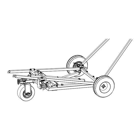
15 SERIES FIELD LOADER S-DRIVE – MOVER KIT 2. FEATURES 2. Features Typical Mover Kit Components Figure 2. Typical Mover Kit Components Split-V Weldment 12 Linkage w/Bushings Right Hand Side Mover Leg 13 Hose Ring 14 OC Assembly Complete w/MTR/PIN LH... -
Page 14: Assembly
Report missing or damaged parts immediately to ensure that proper credit is received from AGI or your representative, and to ensure that any missing parts can be shipped quickly to avoid holding up the assembly process. -
Page 15: List Of Required Tools
15 SERIES FIELD LOADER S-DRIVE – MOVER KIT 3. ASSEMBLY 3.3. List of Required Tools • blocks, stands, jacks and hoists • 3 standard socket sets and wrench sets • 1 torque wrench • 1 standard 25' [7.62 m] tape measure •... -
Page 16: Installing The Ring Gear
3. ASSEMBLY 15 SERIES FIELD LOADER S-DRIVE – MOVER KIT 3.6. Installing the Ring Gear Axle Tire Assembly Ring Gear 1/2" Hex Nut 3.7. Installing the Over-Center Drive The right and left side over-center drive assemblies are shipped fully assembled. Refer to the following illustrations for guidance when installing the over-center drives onto the axle. - Page 17 15 SERIES FIELD LOADER S-DRIVE – MOVER KIT 3. ASSEMBLY Assembly Note: • Position the axle clamp of the over-center drive assembly squarely on the axle. • With the pinion gear flush with the ring gear, bolt the axle clamp to the axle.
-
Page 18: Adjusting The Pinion Gear
3. ASSEMBLY 15 SERIES FIELD LOADER S-DRIVE – MOVER KIT 3.8. Adjusting the Pinion Gear Failure to ensure proper gear meshing will result in gear damage. The pinion gear should mesh with the ring gear to provide maximum tooth contact. -
Page 19: Installing The Drive Lock
15 SERIES FIELD LOADER S-DRIVE – MOVER KIT 3. ASSEMBLY 3.9. Installing the Drive Lock • To prevent equipment damage during transport, disengage gears before towing the machine. Insert the pin through one of the holes in the handle, preventing gears from engaging accidentally during transport. -
Page 20: Assembling The Split Wheel Move
3. ASSEMBLY 15 SERIES FIELD LOADER S-DRIVE – MOVER KIT 3.10. Assembling the Split Wheel Move Left Hand Side Split Mover Arm 5/8" x 1-1/2" Hex Bolt Right Hand Side Split Mover Arm 5/8" Flat Washer Split V-Weldment 5/8" Nylon Lock Nut... -
Page 21: Attaching The Split Wheel Move To The A-Frame Axle
15 SERIES FIELD LOADER S-DRIVE – MOVER KIT 3. ASSEMBLY 3.11. Attaching the Split Wheel Move to the A-Frame Axle Assembly Notes: • Lower the conveyor completely before attaching the mover. • Place the split move assembly beneath the A-Frame and secure it to the axle using bolts. -
Page 22: Installing The Tire Fork Weldment
3. ASSEMBLY 15 SERIES FIELD LOADER S-DRIVE – MOVER KIT 3.12. Installing the Tire Fork Weldment Assembly Note: • Apply grease to the main pivot using grease gun and injecting it through the grease zerk. • Ensure the pivot is securely tightened but can still rotate freely, tighten the slotted hex nut accordingly. -
Page 23: Installing The Cross Brace
15 SERIES FIELD LOADER S-DRIVE – MOVER KIT 3. ASSEMBLY 3.13. Installing the Cross Brace Axle Arm 5/8" x 2" Hex Bolt Top Cross Brace 5/8" Nylon Lock Nut 5/8" Flat Washer Hardware Kit: HRDW-15-110 8210-10011 R1... -
Page 24: Assembling The Slider
3. ASSEMBLY 15 SERIES FIELD LOADER S-DRIVE – MOVER KIT 3. ASSEMBLY 15 SERIES FIELD LOADER S-DRIVE – MOVER KIT 3.9. Assemble the Slider 3.14. Assembling the Slider Note The slider is pre-assembled. The slider is preassembled. STEP - 1... -
Page 25: Installing The Top And Bottom Slider
15 SERIES FIELD LOADER S-DRIVE – MOVER KIT 3. ASSEMBLY 3.15. Installing the Top and Bottom Slider Assembly Note: • The joint must pivot. Do not overtighten the bolts and nuts. Top Cross Brace Slider Mover Cross Bar 3/4" x 3" Hex Bolt 3/4"... -
Page 26: Installing The Mover Wheel
3. ASSEMBLY 15 SERIES FIELD LOADER S-DRIVE – MOVER KIT 3.16. Installing the Mover Wheel Front Axle Weldment Bearing Flange Wheel Assembly 5/8" Nylon Lock Nut 9/16" Wheel Nut 1/8" NPT 90 Degree Grease Zerk 5/8" x 2" Hex Bolt... -
Page 27: Installing The Hydraulic Motor
15 SERIES FIELD LOADER S-DRIVE – MOVER KIT 3. ASSEMBLY 3.17. Installing the Hydraulic Motor Assembly Note: • Leave the locking collars on the bearings loose until hydraulic motor is fully installed. Hydraulic Motor 3/8" x 2-1/2" Hex Bolt Motor Mount 3/8"... -
Page 28: Installing The Linkage And The Steering Cylinder
3. ASSEMBLY 15 SERIES FIELD LOADER S-DRIVE – MOVER KIT 3.18. Installing the Linkage and the Steering Cylinder Steps Description Section 3.18.1 – Installing the Linkage on page 28 Section 3.18.2 – Installing the Steering Cylinder on page 29 3.18.1 Installing the Linkage 3/8"... -
Page 29: Installing The Steering Cylinder
15 SERIES FIELD LOADER S-DRIVE – MOVER KIT 3. ASSEMBLY 3.18.2 Installing the Steering Cylinder Steering Linkage 1" Flat Washer Steering Control Arm with Bushing 1.031 ID X 1.75 OD X 0.25 Thick Flat Washer 2" x 8" Hydraulic Cylinder 1"... -
Page 30: Installing The Control Stand Without The Valve
3. ASSEMBLY 15 SERIES FIELD LOADER S-DRIVE – MOVER KIT 3.19. Installing the Control Stand without the Valve Control Stand 1/2" x 1-1/2" Hex Bolt 1/2" Flat Washer Control Stand Mount Plate 1/2" Nylon Lock Nut Hardware Kit: HRDW-15-107 8210-10011 R1... -
Page 31: Installing The Hydraulic Valve To The Stand
15 SERIES FIELD LOADER S-DRIVE – MOVER KIT 3. ASSEMBLY 3.20. Installing the Hydraulic Valve to the Stand It is recommended to install the valve to the stand after installing the fittings to the valve. Spool Valve 5/16" x 2-1/2" Hex Bolt Valve Mount Guard 5/16"... -
Page 32: Installing The Hydraulic Oil Tank
3. ASSEMBLY 15 SERIES FIELD LOADER S-DRIVE – MOVER KIT 3.21. Installing the Hydraulic Oil Tank Spout Hopper 32" Gear Clamp 1/2FPT-1/2FPTX Female Swivel Coupling 22 L Hydraulic Tank Conveyor Tube/U-Trough 1/2FPT-3/4FPTX Female Swivel Coupling 8210-10011 R1... -
Page 33: Installing The Hydraulic Oil Filter
15 SERIES FIELD LOADER S-DRIVE – MOVER KIT 3. ASSEMBLY 3.22. Installing the Hydraulic Oil Filter Steps Description Section 3.22.1 – Installing the Filter Bracket on page 33 Section 3.22.2 – Installing the Filter Head on page 34 Section 3.22.3 – Installing the Filter Canister on page 35 3.22.1 Installing the Filter Bracket... -
Page 34: Installing The Filter Head
3. ASSEMBLY 15 SERIES FIELD LOADER S-DRIVE – MOVER KIT 3.22.2 Installing the Filter Head Assembly Note: • The hydraulic hoses MUST be installed to ensure that the oil flows to the tank, in the same direction as the arrow on the filter head. -
Page 35: Installing The Filter Canister
15 SERIES FIELD LOADER S-DRIVE – MOVER KIT 3. ASSEMBLY 3.22.3 Installing the Filter Canister Filter Head Filter Canister 8210-10011 R1... -
Page 36: Installing The Hydraulic Hose Tray And Ring
3. ASSEMBLY 15 SERIES FIELD LOADER S-DRIVE – MOVER KIT 3.23. Installing the Hydraulic Hose Tray and Ring Steps Description Section 3.23.1 – Installing the Hose Ring on page 36 Section 3.23.2 – Installing the Hose Bottom Tray (For Top-Mount Drive Conveyor) on page 37 Section 3.23.3 –... -
Page 37: Installing The Hose Bottom Tray (For Top-Mount Drive Conveyor)
15 SERIES FIELD LOADER S-DRIVE – MOVER KIT 3. ASSEMBLY 3.23.2 Installing the Hose Bottom Tray (For Top-Mount Drive Conveyor) Axle Arm 48" Hose Bottom Tray Mover Leg 24" Hose Bottom Tray 1/4" x 1" Self-Drilling Screw (x2 for both 24"... -
Page 38: Installing The Hose Bottom Tray (For Under-Mount Drive Conveyor)
3. ASSEMBLY 15 SERIES FIELD LOADER S-DRIVE – MOVER KIT 3.23.3 Installing the Hose Bottom Tray (For Under-Mount Drive Conveyor) Axle Arm 48" Hose Bottom Tray Mover Leg 70" Hose Bottom Tray 1/4" x 1" Self-Drilling Screw (x5 for 70" Hose Bottom Tray and x2 for 48"... -
Page 39: Installing The Hose Tray Cap (For Top-Mount Drive Conveyor)
15 SERIES FIELD LOADER S-DRIVE – MOVER KIT 3. ASSEMBLY 3.23.4 Installing the Hose Tray Cap (For Top-Mount Drive Conveyor) Leave the hose tray cap open until the hydraulic hose connections are complete. a - 24" Hose Tray Cap a - 48" Hose Tray Cap b - 24"... -
Page 40: Installing The Hose Tray Cap (For Under-Mount Drive Conveyor)
3. ASSEMBLY 15 SERIES FIELD LOADER S-DRIVE – MOVER KIT 3.23.5 Installing the Hose Tray Cap (For Under-Mount Drive Conveyor) Leave the hose tray cap open until the hydraulic hose connections are complete. a - 70" Hose Tray Cap a - 48" Hose Tray Cap b - 70"... -
Page 41: Installing The Double Counter Balance Valve
15 SERIES FIELD LOADER S-DRIVE – MOVER KIT 3. ASSEMBLY 3.24. Installing the Double Counter Balance Valve Double Counter Balance Valve 1/4" x 2" Self-Drilling Screw Mover Leg 8210-10011 R1... -
Page 42: Installing The Line Blocks
3. ASSEMBLY 15 SERIES FIELD LOADER S-DRIVE – MOVER KIT 3.25. Installing the Line Blocks Assembly Note: • Hand tighten the bolts and nuts. 5/16" x 2-1/4" Hex Bolt 5/16" Nylon Lock Nut Line Block 3.26. Installing the Hydraulic Manifold Hydraulic Manifold 5/16"... -
Page 43: Ucx3/Cx3 Awd Hydraulic Components, Fittings, And Hoses
15 SERIES FIELD LOADER S-DRIVE – MOVER KIT 3. ASSEMBLY 3.27. UCX3/CX3 AWD Hydraulic Components, Fittings, and Hoses 3.27.1 Attaching the Hydraulic Fittings 8210-10011 R1... - Page 44 3. ASSEMBLY 15 SERIES FIELD LOADER S-DRIVE – MOVER KIT Components Fittings ❶ Hydraulic Winch 6MJIC-3/8MPT 90 ❷ Hydraulic Motor 9.76 w/hole — 6MJIC-3/8MPT 90 ❸ Hydraulic Cylinder 2 X 8 6FJIC-6MJIC REST .031 Hole 6FJIC-6MJIC REST .031 Hole Hydraulic Cylinder 2 X 15.625 X 1.125 Rod H/ ❹...
-
Page 45: Connecting The Hydraulic Hoses
15 SERIES FIELD LOADER S-DRIVE – MOVER KIT 3. ASSEMBLY 3.27.2 Connecting the Hydraulic Hoses 8210-10011 R1... - Page 46 3. ASSEMBLY 15 SERIES FIELD LOADER S-DRIVE – MOVER KIT Spool Valve Ports Double Counter Balance Valve Ports Hydraulic Manifold Ports To Li� Cylinder To Valve 8210-10011 R1...
- Page 47 15 SERIES FIELD LOADER S-DRIVE – MOVER KIT 3. ASSEMBLY Connections Hose Description Hose (3/8") SB (390")-6FJIC-6FJIC ❶ Hydraulic Winch (T) to ❼ Spool Valve (A4) Hose (3/8") SB (390")-6FJIC-6FJIC ❶ Hydraulic Winch (P) to ❼ Spool Valve (B4) Hose (1/2") SB (360")-8FJIC-1/2"FPTX ❺...
-
Page 48: Hydraulic Hose Routing Overview
3. ASSEMBLY 15 SERIES FIELD LOADER S-DRIVE – MOVER KIT 3.27.3 Hydraulic Hose Routing Overview Assembly Notes: • Assemble Hoses as illustrated. • Keep Hoses free of dirt while assembling. • Keep pressure and return sides aligned. • Tighten after being satisfied that the Hoses are in the proper position. - Page 49 15 SERIES FIELD LOADER S-DRIVE – MOVER KIT 3. ASSEMBLY Valve to Pump and Tank to Pump Hose Routing in Under-Mount Drive Conveyor Hoses Hose (1") SB (198")-12FJIC-3/4"MPT Hose (1/2") SB (456")-8FJIC-8FJIC Components ❻ Hydraulic Tank, 22L, W/ PT FTG ⓫...
- Page 50 3. ASSEMBLY 15 SERIES FIELD LOADER S-DRIVE – MOVER KIT Left Side of the Conveyor Hoses Hose (3/8") SB (390")-6FJIC-6FJIC Hose (3/8") SB (17.5")-6FJIC-6FJIC Hose (3/8") SB (164")-6FJIC-1/2"MPTX Hose (3/8") SB (114")-6FJIC-6FJIC Hose (1") SB (198")-12FJIC-3/4"MPT – Under- Hose (3/8") SB (72")-6FJIC-6FJIC Mount Drive Hose (3/8") SB (55")-6FJIC-6FJIC...
- Page 51 15 SERIES FIELD LOADER S-DRIVE – MOVER KIT 3. ASSEMBLY Spout-End View of the Conveyor Hydraulic Manifold Detail Hoses Hose (3/8") SB (164")-6FJIC-1/2"MPTX Hose (3/8") SB (17.5")-6FJIC-6FJIC Hose (3/8") SB (55")-6FJIC-6FJIC Hose (3/8") SB (114")-6FJIC-6FJIC Components Hydraulic Manifold Assembly Hydraulic Motor 4.6 RS, 1/2 NPTF, 3/8" HOLE, ❾...
-
Page 52: Appendix
4. APPENDIX 15 SERIES FIELD LOADER S-DRIVE – MOVER KIT 4. Appendix 4.1. Bolt Torque Table 2 gives the correct torque values for various hardware. Tighten all bolts to the torque specified, unless otherwise noted. Check tightness periodically, using Table 2 as a guide. -
Page 53: Fittings Torque Values
15 SERIES FIELD LOADER S-DRIVE – MOVER KIT 4. APPENDIX 4.2. Fittings Torque Values These specifications are for carbon steel. With Zinc plating always lubricate threads and seals. For stainless steel, use the high value of the torque range of steel. For brass, use 70% of the torque value of steel. For mixed metals, use the torque of the lower of the two metals. - Page 54 4. APPENDIX 15 SERIES FIELD LOADER S-DRIVE – MOVER KIT Table 5. Fitting Torque values for O-Ring Boss (ORB) Min. Torque ft-lbs Max. Torque ft-lbs Dash Size Table 6. JIC 37° Flare Tube Fitting (J/JFS) Torque N-m Tube Size Thread UNF-2A...
- Page 55 15 SERIES FIELD LOADER S-DRIVE – MOVER KIT 4. APPENDIX 8210-10011 R1...
- Page 56 AGI is a leading provider of equipment solutions for agriculture bulk commodities including seed, fertilizer, grain, and feed systems with a growing platform in providing equipment and solutions for food processing facilities. AGI has manufacturing facilities in Canada, the United States, the United Kingdom, Brazil, South Africa, India and Italy and distributes its products globally.
Need help?
Do you have a question about the 15 Series and is the answer not in the manual?
Questions and answers