
Related Manuals for Teac TD-35


Summary of Contents for Teac TD-35
- Page 1 Teac Corporation Ver 2006/ 4/18 ...
- Page 2 Thank you for purchasing a TD‑35 Digital Strain Indicator. Read this manual and understand the contents correctly before using the product for the best performance of the TD‑35. Warranty This is a product that has passed a strict in‑house quality inspection. We will repair or exchange it upon any failure or trouble of this product according to the service standard prescribed by TEAC Corporation. This TEAC warrantee shall also fully comply with any local product liability law. Teac Corporation Headquarter Sales Department: 3‑7‑3, Nakacho Musashino‑shi, Tokyo 180‑8550 Japan TEL: (0422) 52‑5082 Contacts for Technical Support Business Solutions Company Sales Department Sales 1 Group TEL (0422) 52‑5074 E‑mail:tic̲cs@tic.teac.co.jp Hours Mon〜Fri (except Holidays) AM 9:30〜12:00、PM 1:00〜5:00 TEAC Corporation Web Page http://www.tic.teac.co.jp/ 2 ...
-
Page 3: Table Of Contents
Index 1. Overview..................4 2. Features ..................4 3. Configuration ................4 4. Standard Accessories ..............6 5. Specifications ................6 6. Operation..................8 7. Measuring Method..............12 8. Miscellaneous Materials............15 9. External View ................18 ... -
Page 4: Overview
1. Overview The TD‑35 is a digital strain indicator that suits various strain gauge base sensors, used for the indication of pressure, load or torque as well as the load‑cell. This offers the display resolution of ±20000×10‑6 strain. In addition to the display in strain unit, it is also capable of converting the value into a real unit such as in Newton (N) using the preset sensor‑output‑value (mV/V) for direct reading convenience. This operates with a built‑in battery (AAA type) or external AC power supply (using an AC adaptor). 2. Features 1) Small and compact size. 2) All necessary functions for the static strain indicator are equipped and ready to make a measurement simply by connecting the sensor. 3) Suited for almost all types of strain gauge base sensors such as load and pressure. 3. Configuration 1) Pre‑amp 6) Bridge power supply 2) A/D converter 7) Operation controller 3) Display circuit 8) Internal battery 4) Ref. power circuit ... - Page 5 5 ...
-
Page 6: Standard Accessories
4. Standard Accessories 1) ZR6(Y) Oxyride dry‑cell battery ・・・・・・・・・・・・・・・・ Qty 4 2) Operation Manual ・・・・・・・・・・・・・・・・・・・・・・・・・・・・・・・ Qty 1 3) AC Adapter ・・・・・・・・・・・・・・・・・・・・・・・・・・・・・・・・・・・・・ Qty 1 5. Specifications Input : Strain gauge type connector Input connector : NDI‑7R connector Bridge power supply : Approx. DC 2.5V, Max current 30mA −6 Input range : ±20000×10 strain(±10mV/V) −6 Zero shift : ±10000×10 strain, digital adjustment −6 Display : Strain display mode : 0 ±20000×10 strain ... - Page 7 150mm(W)x100mm(D)x40mm(H) (excluding umbo) Dimension : Weight : Approx. 500g (including ZR6(Y) dry‑cell battery) 7 ...
-
Page 8: Operation
6. Operation 6.1 Functions and controls in rear panel ① DC IN ‑ External Power Input Connector The power input connector when AC power is used. Use the supplied accessory AC adapter for the external power. ② POWER ‑ Power Switch The power switch for the internal battery or the external power. When the external power is connected, the internal battery is used and not consumed. ③ LIGHT ‐ Back‑light Switch for LCD The ON/OFF switch for the display back‑light. Note that twice as much power is consumed when it is turned on in battery operation. - Page 9 When it is OFF, the zero cancel operation is not performed and it displays the strain quantity with reference to the TD‑35 internal zero in the selected display mode set in ④. This can be used to check the initial balance value of the strain gauge or strain gauge sensor. ⑥ INPUT ‐ Sensor Input Connector The NDIS standard input connector for the strain gauge sensor. Applicable plug model is PRC03‑12A10‑7M10.5 made by Tajimi‑Musen. Pin Signal (Cable Color) A Bridge Voltage + (Red) B Bridge Output − (Black) C Bridge Voltage − (Blue) D Bridge Output + (White) E...
- Page 10 6.2 Operating Function and Controls ⑦ ↑ Key Used to increase the setting value ⑧ → Key Used to move the digit during setting value ⑨ ↓ Key (ZERO‑RESET) Used to decrement the setting value or zero cancellation when used together with ⑬ key. ⑩ ← Key Used to move the digit while setting value ⑪ ENTER Key ...
- Page 11 Battery Storage It is installed in the area where the lid in the rear panel slides. Rear View MODEL NO. TD−35 DIGITAL STRAIN INDICATOR 5‑12V 0.3‑0.14A TEAC INSTRUMENTS CORP SERIAL MADE IN JAPAN → Slides to this direction Battery Storage 11 ...
-
Page 12: Measuring Method
7. Measuring Method 7.1 Notes in Measurement ■ TD‑35 is a strain measuring instrument primarily for the static strain (DC 〜about 3Hz). The A/D sampling frequency of TD‑35 is 6Hz. For the strain measurement of a higher frequency component, use the dynamic strain measuring instrument instead. ■ Because the signal from the strain gauge or sensor is minute, pay special attention to noise intrusion. For the signal cable from the sensor, use the dedicated 4‑wire shielded cable. ■ Use it where the signal cable does not touch or run parallel to the power line. Also keep the signal cable away from any strong magnetic field generating devices such as a motor or a power transformer. ■ During operation, avoid direct sunlight, high temperature, high humidity, or places where dew condensation may occur such as rapid temperature or humidity changes. 7.2 Wire Connection This is a strain indicator for measuring the strain gauge type sensor gauge output such as a load‑cell. For the strain measurement of an individual strain gauge, use the BX‑100 strain gauge bridge box with the 1‑gauge or the 2‑gauge method. 7.3 Measurement ... - Page 13 strain by referencing the material in the back of this manual, then make a zero adjustment. ■ Peak Hold Display Press ⑫ PEAK HOLD button and the display shows [P] then the peak hold operation starts. It continues until ⑫ PEAK HOLD button is pressed again. 7.3.2 User Unit Display Measurement Connect ⑥ INPUT in the rear panel to a sensor, switch ④ INDICATION to USER, and the display mode becomes a user display mode. The displayed value is computed according to the user defined physical quantity (Kg, etc.) vs. sensor sensitivity (mV/V) setting. ■ Sensor Sensitivity (mV/V and rated capacity) setting procedure Press ⑪ ENTER while holding ⑬ SELECT in the operation panel, and the display changes to C 00.000. Move to a desired digit using ⑧( or ⑩( →) ←) key, and select values using ⑦(↑) or ⑨(↓) key. Once a desired value is set, press ⑪ ENTER. Then the rated capacity is displayed as G 00000. Move to a desired digit using ⑧ or ⑩ key, and select values using ⑦ (→) (←) (↑) or ⑨ key. (The rated capacity is a value found in the sensor s (↓) data sheet) ...
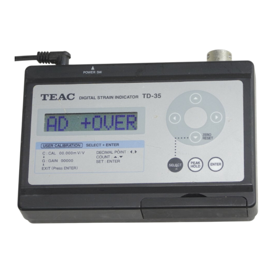
- Page 14 strain quantity converted value can be displayed by moving the decimal point. However, not all digits in display are guaranteed due to the stability or accuracy, etc. ■ Initial Setting Turn ② POWER on while holding both ⑬ SELECT button and ⑦ ↑ key simultaneously, and keep holding both keys until the measurement value appears. The unit is then initialized to the user unit of 1.000mV/V and the displayed value of 2000. 7.4 Alarm Display Alarm during measurement ■ OVER Description:Displayed value exceeds the limit of 9999 Countermeasure:If in user unit mode, adjust the maximum digits or the coefficient so that the expected maximum measurement value fits in 9999. ■ OFF OVER Description :Input value exceeds the offset adjustable range. ...
-
Page 15: Miscellaneous Materials
:Communication with internal A/D failed. (Reboot the unit) 3. AD ERR :Invalid written data in ROM. 4. CAL ERR 5. ROM WERR :ROM write failure. 6. ROM RERR :ROM read failure. 7. ROM EERR :ROM erase failure. :Internal process error. 8. SYS ERR 9. BAD CALD :Calibration failure due to the abnormal ROM data. ... - Page 16 The resister to be used (RZ) directly influences the zero drift characteristic of the sensor, therefore use the resister that has an excellent temperature coefficient. (25ppm/℃ or less recommended) This method can be used for sensitivity calibration when the indicator is replaced. In general, the initial calibration is done by combining with a sensor and an actual applied load. However, when a re‑calibration is not feasible, it can be done with the following substitution method without using an actual load. After initial calibration, connect an appropriate resister (RZ) to one side of the bridge and record the displayed value, then remove the resister. When the indicator is replaced for a reason of servicing or so forth, connect the same resister used above, adjust ZERO balance, and make a sensitivity adjustment so that the reading value becomes the same as the previously recorded value. The table in next page shows the resister values and the shift amount when a resister is connected to one side of the bridge circuits having two different resister values, 350Ω and 120Ω. These resister values are calculated amounts and they may be off due to the errors in the input and the output resistance of the sensor. Use these values only as an estimate or guideline. 16 ...
- Page 17 Added resister value versus input conversion strain of the bridge circuit with 350 Ω and 120Ω resistance. List of switch settings on measurement items 17 ...
-
Page 18: External View
1.6 40 150 TD− 35 MODEL NO. DIGITAL STRAIN INDICATOR 5‑12V 0.3‑0.14A TEAC INSTRUMENTS CORP SERIAL MADE IN JAPAN 18 ...
Need help?
Do you have a question about the TD-35 and is the answer not in the manual?
Questions and answers