Table of Contents
Advertisement
Quick Links
Advertisement
Table of Contents

Related Manuals for Teac TD-01 Portable


Summary of Contents for Teac TD-01 Portable
- Page 1 D01285105A Portable Indicator Owner’s Manual TD-01 Portable...
-
Page 2: Introduction
Introduction Thank you for purchasing the TD-01 Portable Indicator. Disclaimers Please read this document in its entirety before using the product to get the best performance and ensure safe and Information is given about products in this manual only proper operation. -
Page 3: Safety Information
Safety information This document describes the safety instructions for the operation of the digital indicator. Before operating the product, read this doc- ument carefully to familiarize yourself with the unit. Follow the instructions below to avoid risk of serious personal injury and V WARNING death. - Page 4 Safety information V CAUTION Follow the instructions below to avoid risk of personal injury or property damage. Put the unit power into standby before doing any of the following. o Installing load cells o Replacing batteries o Connecting other external equipment Never touch the connectors while the product is turned on.
-
Page 5: Model For Europe
Improper disposal of waste electrical/electronic Changes or modifications to this equipment not expressly equipment and batteries/accumulators can have seri- approved by TEAC CORPORATION for compliance could ous effects on the environment and human health void the user’s authority to operate this equipment. -
Page 6: Table Of Contents
Contents Introduction ..........2 4-9-4. - Page 7 Contents 6-5-3. Clear Digital Zero ....... 41 6-6. Select Data Output ........42 7.
-
Page 8: Installing Batteries
Installing batteries Remove the back cover and insert the batteries. Button cell battery Close the cover after inserting the batteries The button cell battery is used to back up the clock. Misuse of batteries could cause them to rupture or leak, which might result in fire, Replace the button cell battery if the clock display shows that it is January 1, 2000 after the power is turned on, except for the injury or the staining of nearby materials. -
Page 9: Names And Functions Of Parts
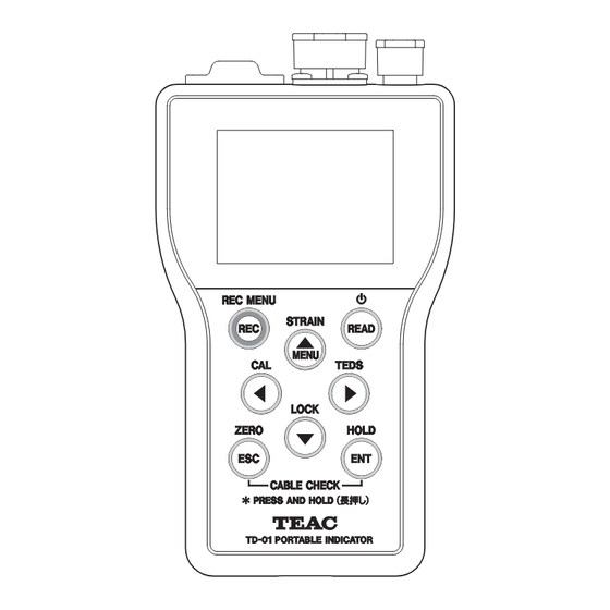
1. Names and functions of parts 1-1. Front panel When Cal. Value Lock is OFF, press and hold to use the REC/REC MENU button Zero Balancing function (page 37). When Cal. Value Lock is ON, press this to forcibly set the indicator value to zero (Digital zero function). -
Page 10: Top Panel
1. Names and functions of parts LOAD: A/D converter plus over 1-2. Top panel −FULL: display minus over (less than the minimum display value) FULL: display plus over (greater than the maximum dis- play value) −OVER FULL: Input is outside the input range (neg- ative value) OVER FULL: Input is outside the input range (posi-... -
Page 11: Sensor Signal Input Terminals
1. Names and functions of parts 1-3. Sensor signal input terminals 1-4. Bottom panel Connect one sensor to either INPUT 1 or INPUT 2. Do not con- nect sensors to both inputs. TEDS(F) GND(G) +EXC(A) SIG(B) EXC(C) o Connector covers are attached to the connectors. Remove the connector covers to use the connectors. -
Page 12: Screen Transition Diagram
1. Names and functions of parts 1-5. Screen transition diagram Press and hold Power supply ON o The last open screen will reappear. Press and hold Indicator value Graph Static Strain Disp. Mode Simple indication Memory and list selection/display Function Menu Press and hold Equivalent Input... -
Page 13: Home Screen
1. Names and functions of parts Power status 1-6. Home Screen : Operating on bus power from the USB port. The indicator value or graph display is shown after the unit is turned on. (The last open screen will reappear.) : Operating on batteries Use the g and t buttons to change screen views. -
Page 14: Graph Screen
1. Names and functions of parts Press and hold 5+b Unit This is not indicated on the front panel, so it can be used to prevent unlocking when not desired. This is the set position (page 30). Press and hold 5+b to unlock this control lock. This can also be used to unlock when control lock High limit value has been set by pressing and holding b. -
Page 15: Snapshot
1. Names and functions of parts Waveform 1-7. Static Strain Disp. Mode Values between the low limit and the high limit are Set whether to show the input signal with the strain amount shown in green. unit (μst). Values above the high limit or below the low limit are Use when checking sensor output and unsteadiness in indica- shown in red. -
Page 16: Shortcut Menus
2. Shortcut menus 2-1-2. Setting Memory 2-1. Memory and list selection/display Select the setting value memory. Press the READ button to open the following screen. This is the same setting screen as System settings 1 w Setting memory. See “10-1 Setting Memory” on page 55 2-1-1. -
Page 17: Indicator Value List
2. Shortcut menus 2-1-3. Indicator value list Mode Indicator recording mode 1: When REC key pressed (KEY) Indicator value list 2: When stability detected (AUTO) 3: When hold stops (ZONE) Sensor Sensor value memory number Indicator value Setting value list Indicator value h:m:s Time of recording... -
Page 18: Graph List
2. Shortcut menus 2-1-4. Graph list Deleting data Graph list Graph analysis When the graph list is open, press and hold the REC and ESC buttons at the same time to delete the most recently recorded data. For other ways to delete data, see “11-3 Recorded data dele- tion”... -
Page 19: Indicator Recording Mode
2. Shortcut menus Layered display of graphs When stability detected (AUTO) Indicator values will be recorded when stability is detected. Press the ENT button when the graph analysis screen is open. For stability detection methods, see “6-2 Motion Detect” on page 39. When hold stops (ZONE) Indicator values will be recorded when hold goes from ON to OFF. -
Page 20: Making Connections
2.5V, the sensor could be damaged. Button Connecting a TEDS sensor or one with 4 wires Strain gauge transducer TD-01 Portable Remove 7–8 mm of the covering from the wire being connected, and twist it so that the tip does (TEDS) TEDS Data not come apart. -
Page 21: Interrupted Wire Checking
3. Making connections 3-3. Interrupted wire checking Press and hold the ESC and ENT buttons to check for inter- rupted wires and show the results on the display. If the possibility of an interruption is detected, the location of the possible interruption will be shown in red. Interruptions can occur not only in strain gauges, but also in load cell cables. -
Page 22: Settings
4. Settings The following screen appears when you select 4-1. Basic operation Calibration w Equivalent Input Calibration. Press the MENU button to open the Function Menu. Selected item Changing a series of setting values. Depending on the menu item, setting screens might appear in a series. -
Page 23: Selecting Setting Values From Options
4. Settings 4-2. Selecting setting values from 4-3. Inputting numerical setting values options The selected digit appears dark with a white background. The current value has a white background. Other options have gray backgrounds. Use the g and t buttons to change the selection, and use the 5 and b buttons to change the value. -
Page 24: Changing The Decimal Point Position
4. Settings 4-4. Changing the decimal point 4-5. Lock position You can prohibit the changing of calibration and setting values. The decimal point position can only be changed for the Rated When locked, “Locked” appears with a white background at the Capacity. -
Page 25: Returning To The Home Screen
4. Settings 4-6. Returning to the Home Screen 4-9. Setting menu list 4-9-1. Calibration Calibration Equivalent Input Calibration (page 32) Sensor value memory Rated Output Rated Capacity Zero Balancing Select EU Cal. Value Lock Actual Load Calibration (page 33) Sensor value memory Zero Balancing Use the g and t buttons to select TOP, and press the ENT Rated Capacity... -
Page 26: Condition Setting
4. Settings 4-9-2. Condition Setting 4-9-6. System settings 1 Condition Setting System settings 1 Filter (page 38) Setting Memory (page 55) Motion Detect (page 39) D/A Converter (page 55) Time D/A output Width D/A Zero Zero Tracking (page 40) D/A Full Scale Time D/A Max. -
Page 27: Setting Value List
4. Settings 4-10. Setting value list 4-10-1. Calibration Cal. Setting Setting Unit Default Value value value Item Setting Format Setting range/options display value Lock lock memory Sensor value memory Options 1 to 6 Rated Output Input mV/V 3.000 0.300 to 5.000 ... -
Page 28: Condition Setting
4. Settings 4-10-2. Condition Setting Cal. Setting Setting Unit Default Setting range/options/ Value value value Item Settings Format display value operation Lock lock memory Filter Select Num. of Moving Options OFF, 16, 32, 64, 128, 256, 512, Avg. 1024, 2048 Motion Detect Time... -
Page 29: System Settings 1
4. Settings 4-10-5. System settings 1 Cal. Setting Setting Unit Default Value value value Item Setting Format Setting range/options display value Lock lock memory Setting value memory Options 1 to 6 D/A Converter D/A output Options ON, OFF D/A Zero Input Set unit 000.00... -
Page 30: Calibration
5. Calibration Sensor check before calibrating Connecting the unit with a strain gauge transducer and setting how the indicator values will be shown is called "cali- After connecting a sensor and turning the unit on, calibration bration". The following three calibration methods can be used is not possible if the indicator value is unstable or an error with the unit. -
Page 31: Procedures Shared By All Calibration Methods
5. Calibration Use the 5b buttons to change the selection, and 5-1. Procedures shared by all cali- select in order System Settings 1 w Lock bration methods The three calibration methods are equivalent input calibra- tion, actual load calibration and TEDS calibration. All the calibration methods have the same procedures before and after calibration. -
Page 32: Equivalent Input Calibration
5. Calibration Press the ENT button to confirm the selection. 5-2. Equivalent input calibration This method determines the calibration value by recording rated output and rated capacity values from a test results table. Use this to calibrate easily when an actual load cannot be applied. -
Page 33: Rated Output
5. Calibration 5-2-3. Rated Output 5-3. Actual Load Calibration Input range: 0.300–5.000 mV/V Set the rated output of the strain gauge transducer being Calibrate by applying an actual load to the sensor. used. Sensor value memory 5-2-4. Rated Capacity selection Set the rated capacity of the strain gauge transducer being used. -
Page 34: Zero Balancing
5. Calibration 5-3-3. Zero Balancing 5-3-5. Select EU With no load on the sensor, press the ENT button. Select the unit that corresponds to the indicator value. During zero balancing, a pop-up appears to show that it is in progress. When zero balancing completes, the setting screen for the next procedure appears. -
Page 35: Teds Calibration
5. Calibration 5-4-2. Rated Output/Rated Capacity display 5-4. TEDS calibration After reading the TEDS data, the Rated Output/Rated Capacity is shown. A TEDS sensor has calibration information, including rated out- put and rated capacity, stored in its memory. Rated capacity digit shown during TEDS calibration TEDS calibration reads this calibration information to automati- cally record calibration values. -
Page 36: Select Eu
5. Calibration 5-4-4. Select EU 5-6. Select Min. Grid Options: N, kN, kPa, MPa, g, kg, sht, ton, mN·m, N·m, kN·m, none Select the unit that corresponds to the indicator value. Set the minimum digital change of the indicator value. o If a sensor with TEDS built in is connected, the read unit will be set. -
Page 37: Select Eu
5. Calibration 5-8. Select EU 5-10. Zero Balancing Select the indicator value unit. You can conduct Zero Balancing calibration even without Select the unit that corresponds to the indicator value. resetting the calibration value. Set Cal. Value Lock to OFF. See “5-1-1 Locking and unlocking calibration values”... -
Page 38: Condition Settings
6. Condition Settings 6-1. Filter 6-1-1. Select Num. of Moving Avg. Set the moving average number for the measured data. Options: OFF, 16, 32, 64, 128, 256, 512, 1024, 2048... -
Page 39: Motion Detect
6. Condition Setting 6-2. Motion Detect Set the parameters used to detect stability. The indicator value is judged to be stable if a difference less than the set width occurs between the current indicator value and the indicator value 100 mSec before, and this continues for the set time. The Motion Detect function is closely related to the comparison mode. -
Page 40: Zero Tracking
6. Condition Setting 6-3. Zero Tracking This function automatically tracks drift and other gradual changes to the zero point. With Zero Tracking, when the zero point moves no more than the set width, the indicator value is automatically adjusted to zero each set time interval. -
Page 41: Digital Zero Offset
6. Condition Setting 6-5-2. Digital Zero Limit Value 6-4. Digital Zero Offset Set the range for Digital Zero capture. (The setting value unit is the same as for the indicator value.) The set value is subtracted from the measured value (digital zero). -
Page 42: Select Data Output
6. Condition Setting 6-6. Select Data Output Select the data output from the D/A Converter. Select Data Output has the following two options. The hold value is output in coordination with the display. The input is output as is. -
Page 43: Comparison Setting
7. Comparison Setting 7-1. Comp. Value Setting 7-2. Comp. Mode Setting Use this function to set the high limit and low limit values, Set the conditions for judging high limit and low limit. compare them with indicator values, and turn judgment dis- play ON for each one. -
Page 44: Hysteresis
7. Comparison Setting 7-3. Hysteresis This function applies a width to switching from ON to OFF for high limit and low limit judgment display. If the indicator value fluctuates near a value, causing judgment display to chatter between ON and OFF, adjustment of the hysteresis value can prevent this chattering. -
Page 45: Nearly Zero
7. Comparison Setting 7-4. Nearly Zero Set the range in which indicator values are evaluated as being nearly zero. NOTE The Nearly Zero judgment result is closely related to high limit and low limit judgment display. See “7-2 Comp. Mode Setting” on page 43 for details. -
Page 46: Hold Function Setting
8. Hold Function Setting 8-1. Hold Mode Hold Mode has four settings. No hold SAMPLE Sample and hold PEAK Peak hold BOTTOM Bottom hold NOTE Press and hold the ENT button to turn hold on/off. The hold status is shown at the bottom of the display. -
Page 47: Sample And Hold
8. Hold Function Setting 8-1-1. Sample and hold Press and hold the ENT button to hold the indicator value. Press and hold the ENT button to hold the indicator value, and press and hold it again to stop holding the value. Indicator value Sensor input value... -
Page 48: Peak Hold
8. Hold Function Setting 8-1-2. Peak hold 8-1-2-1. No zone definition After pressing and holding the ENT button to turn hold on, the maximum value (peak value) in the indicator value positive direction is shown held. Press and hold the ENT button again to turn hold off, clearing the peak hold. When holding, the peak value is also reset by pressing the CLEAR (ESC) button. -
Page 49: Zone Definition Used
8. Hold Function Setting 8-1-2-2. Zone definition used The indicator value when the hold operation completes continues to be shown. When holding, the peak value is reset by pressing the CLEAR (ESC) button. Indicator value Indicator value Sensor input value When zone definition Time When holding... -
Page 50: Bottom Hold
8. Hold Function Setting 8-1-3. Bottom hold 8-1-3-1. No zone definition Press and hold the ENT button to turn hold on and hold and display the minimum (bottom) indicator value. Press and hold the ENT button again to turn hold off, clearing the bottom hold. When holding, the bottom value is also reset by pressing the CLEAR (ESC) button. -
Page 51: Zone Definition Used
8. Hold Function Setting 8-1-3-2. Zone definition used The indicator value when the hold operation completes continues to be shown. When holding, the bottom value is reset by pressing the CLEAR (ESC) button. Indicator value Indicator value Sensor input value When zone definition Time When holding... -
Page 52: Zone Definition
8. Hold Function Setting 8-2. Zone Definition When set to ON, the indicator value will continue to be shown after the hold ends. Pressing the CLEAR (ESC) button will clear the held value. Options: ON, OFF 8-3. Auto Zero Set whether or not to automatically execute a Digital Zero when a hold starts (ON/OFF). -
Page 53: Graph Settings
9. Graph settings 9-1. Time axis setting (X) 9-3. Trigger mode Set the width of the time axis. Enable/disable trigger operation Trigger disabled 9-2. Indicator value axis setting (Y) Trigger enabled Set the range of indicator values displayed. 9-4. Trigger 9-4-1. -
Page 54: Trigger Level
9. Graph settings 9-4-2. Trigger level Set the indicator value level that causes trigger operation. The trigger point is when the indicator value reaches the set trigger level value from the direction set by the trigger polarity. 9-4-3. Trigger position This sets the display position of the cursor. -
Page 55: System Settings 1
10. System settings 1 10-1. Setting Memory 10-2. D/A Converter You can save up to 6 memories with setting values and switch The D/A Converter allows for analog output that corresponds among them. to the unit indicator value. The analog output range can be set to either ±1V or ±2V volt- age output. -
Page 56: D/A Zero
10. System settings 1 10-2-2. D/A Zero Setting example 2 Set the indicator value that you want to output for D/A Zero D/A Zero 020.00 (0V voltage). D/A Full Scale 100.00 Indicator value D/A output 120.00 20.00 −80.00 −1 V Setting example 3 10-2-3. -
Page 57: D/A Max. Voltage
10. System settings 1 10-2-4. D/A Max. Voltage 10-3. Lock Set the maximum D/A voltage. The load also uses the same output voltage range. For example, when set to 1V, +1 V will be 10-3-1. Cal. Value Lock output when the “10-2-2. D/A Zero” and “10-2-3. D/A Full Scale” setting values are added. -
Page 58: Brightness
10. System settings 1 10-4. Brightness 10-5. Auto power off Adjust the brightness of the LCD screen backlight and the time Set the amount of time without any button operations until until it dims. the unit enters standby. 10-4-1. Brightness Select OFF, 2 min., 5 min.,10 min, 30 min or 60 min. -
Page 59: Reset To The Factory Settings
10-9-2. Date & time setting 10-8. Device number Set the current time for the clock. You can give this unit a unique number. Do this when using multiple TD-01 Portable units, for example. o Press the ENT button after setting all items. -
Page 60: System Settings 2
11. System settings 2 11-1. Battery type 11-3. Recorded data deletion Set the type of AA batteries. This is used to estimate remaining Saved indicator values and graph data can be deleted. battery charge. You can select which data is deleted first using “Indicator” and “Graph”... -
Page 61: Teds Settings
12. TEDS Settings By connecting a sensor that supports IEEE1451.4 Transducer 12-1. TEDS Data Electronic Data Sheets (TEDS) to the unit, the Rated Output stored in the sensor can be loaded and this can be applied to Select TEDS Data to show the following items. calibration of the indicator with this function. -
Page 62: Error Message List
13. Error message list Message Explanation LOAD ADC plus over −LOAD ADC minus over FULL Display plus over (greater than maximum display value) −FULL Display minus over (less than minimum display value) OVER FULL Input is exceeding maximum input range (5.0 mV/V) −OVER FULL Input is less than minimum input range (−5.0 mV/V) ZERO OVER... -
Page 63: Specifications
±5 mV/V Calibration range 0.3 mV/V – 5.0 mV/V Equivalent input/ Calibration Within 0.1% F.S. (when using a 1m standard TEAC Φ8, 6-core shielded cable with 350Ω imped- TEDS precision ance, when 5mV/V) Nonlinearity Within 0.01% F.S. + 1 digit (when 5mV/V) - Page 64 14. External drawings Dimensions in millimeters (mm)
-
Page 65: Block Diagram
15. Block diagram Gain adjustment Strain amplifier Filter circuit circuit Bridge Voltage A/D conversion Standard voltage source LCD display equipment TEDS TEDS memory EEPROM... - Page 68 TEAC CORPORATION 1-47 Ochiai, Tama-shi, Tokyo 206-8530 Japan Phone: +81-042-356-9154 1216 MA-2363A...
Need help?
Do you have a question about the TD-01 Portable and is the answer not in the manual?
Questions and answers