Table of Contents
Advertisement
Quick Links
Z
Strain gauge load cell Instructions for Use
TU-NR-C-G
Tension/Compression Load Cell
Introduction
Thank you for purchasing the TU-NR-C-G load cell.
Please read this document completely before using this
load cell to achieve its best performance and ensure safe
and proper operation.
o Company names and product names in this document are the
trademarks or registered trademarks of their respective owners.
Included accessories
If anything is missing or damaged, contact the retailer
where you purchased the product.
Test report × 1
Instructions for Use (this document) × 1
IMPORTANT SAFETY INSTRUCTIONS
WARNING
V
If something abnormal occurs
Request repair from the retailer where you purchased
the product.
Do not open the cover.
Never remove the cover from this unit. Doing so could
cause malfunction. Request inspection and repair from the
Screw types and tightening torques
Center screw section
Rated
Dimension
Tightening
of load cell
capacity
torque
screw hole
1 kN
96 N·m M12 × 1
2 kN
96 N·m M12 × 1
5 kN
96 N·m M12 × 1
10 kN
96 N·m M12 × 1
20 kN
96 N·m M12 × 1
50 kN
400 N·m M20 × 1.5
100 kN
1.3 kN·m M32 × 2
200 kN
3.2 kN·m M40 × 2
Use screws with a strength grade of 12.9.
In addition, the length of thread engagement for the screw
and the mounting part (internal threads) should be about
twice the nominal diameter of the screw.
Please consult with us if you are uncertain about screw
selection, for example.
o Tighten with the torque shown in the "Screw types and
tightening torques" table to prevent the load button
or load rod from becoming loose. Be sure not to apply
torque that exceeds the tightening torque shown
in the table even when removing an attached load
button or load rod.
A thread-locking fluid can be used on the screw, but
be aware that this could prevent removal of the load
button or load rod.
o When connecting a load button or load rod to this unit
(or disconnecting one), check the values in the Values
Table of the Specifications.
o When using with tension, consider the detent of all the
screws, and consider implementing inspections before
starting work, for example.
In addition, also consider examinations to prevent
accidents caused by falling objects due to damaged
load cells resulting from overloads and unbalanced
loads, for example.
D01396001A
retailer where you purchased the product. Do not alter this
unit. Doing so could cause malfunction.
Do not put foreign objects or water, for example,
into the unit.
Do not place a container that holds water, for example, on
top of this unit. If liquid is spilled, for example, and enters
the unit, this could cause malfunction.
Do not use the unit with any power supply voltage
other than that specified.
Do not use the unit with any power supply voltage other
than that specified. Doing so could cause malfunction.
CAUTION
V
Unsuitable installation locations
Do not place the unit in the following types of locations.
Doing so could cause malfunction.
o Locations where it might be exposed to smoke or steam,
such as near a kitchen table or humidifier
o Unstable locations, including unsteady stands and
tilted places
o Locations that are very humid or dusty
o Locations that are exposed to direct sunlight
When not using the unit for a long time
For safety, cut the power supply when not using this unit
for a long time.
Do not operate a damaged unit.
Precautions for use
o This unit is not built to be water or splash resistant,
and it cannot be used in conditions when the relative
humidity is high. Moreover, use in atmospheres with
corrosive gases should be avoided.
o Be careful to prevent water, oil and other substances
from getting on the unit.
o Avoid use in conditions where condensation could occur.
Precautions when placing loads on the unit
Flange bolt section
Dimension
o Make sure the load is perpendicular to the surface to
Tightening
of load cell
torque
which this unit is attached.
screw hole
o Apply the load so that it is centered on the center of
10 N·m
M6
10 N·m
M6
the unit. If the load is not centered (eccentric load),
10 N·m
M6
twisting, for example, and measurement errors could
10 N·m
M6
occur. This could even result in damage.
10 N·m
M6
25 N·m
M8
43 N·m
M10
190 N·m
M16
F is the correct load orientation
F1 is an eccentric inclined load
F2 is an eccentric load
o If the load receiving area is contacted by something that
is at a different temperature and the load is increased,
the values output by this device could become unstable,
making accurate measurement impossible. In such a
case, wait until the temperature difference ceases to
exist before measuring.
o Do not apply any load to the area shown by shading
with diagonal lines in the illustration below. Applying a
load to the shaded area will break the load cell.
o Connect cores to the load cell after discharging (elim-
inating) static electricity from your body.
o If the surrounding temperature changes suddenly, the
values output by this device could become unstable,
making accurate measurement impossible.
(This could occur, for example, in a location blown by
warm or cold air.)
o Conduct load calibrations periodically.
Installation procedures
o Install this unit in a place where the structure is level
and can sufficiently bear the load being used. Output
precision could be affected if the attachment surface
does not meet parallelism and flatness requirements.
o Refer to Figure 1 for use with only compression loads.
Refer to Figure 2 for use with tension/compression loads.
o Attach a load button when using with compression.
When using with tension, attach a load rod, for example.
Load button
Figure 1. Compression
o Insert screws (steel hexagon socket head cap
screws) into the screw holes near the edge of the
load cell, and fix it to the flat attachment surface.
(Output precision could be affected if the attachment
surface is not flat.) The size of the screws used and their
number depends on the rated capacity (model name)
of the load cell as shown below.
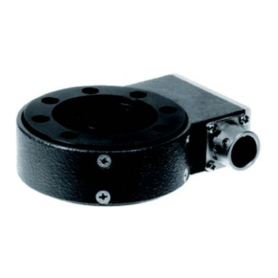
Electrical connection of load cell
Connect as shown in the illustration below. Incorrect con-
nections could result in inability to balance and in errors
occurring in the output voltage when loads are applied.
Receptacle in device
F1
F
F2
o This unit does not support remote sense.
See the operation manuals of indicators and strain
amps that support remote sense for how to connect
sensors with those units.
o The shield is connected to the main body of this prod-
uct. For this reason, if grounding is necessary because
of external noise or another issue, arrange to ground
the shield to a part other than the body of this unit,
for example.
o Use a specialized cable when replacing the cable or to
increase the length. (Please consult with us.)
Load
Load
Load rod
direction
direction
Always ensure a gap
Figure 2. Compression/
tension
A
B
C
D
E
NDIS-compliant receptacle
Advertisement
Table of Contents

Related Manuals for Teac TU-NR-C-G


Summary of Contents for Teac TU-NR-C-G
- Page 1 Unsuitable installation locations does not meet parallelism and flatness requirements. Thank you for purchasing the TU-NR-C-G load cell. Do not place the unit in the following types of locations. o Refer to Figure 1 for use with only compression loads.
- Page 2 4) Malfunction or damage caused by fire, earthquake, water, lightning or other property rights and other rights related to them. TEAC Corporation will bear no respon- natural disaster sibility for infringements on third-party intellectual property rights or their occurrence 5) Malfunction or damage caused by external factors, including power supplies and because of the use of these products.
Need help?
Do you have a question about the TU-NR-C-G and is the answer not in the manual?
Questions and answers