
Related Manuals for Teac TD-280T


Summary of Contents for Teac TD-280T
- Page 1 DIGITAL TRANSDUCER INDICATOR TD-280T OPERATION MANUAL Please read this book carefully before using this product TEAC CORPORATION September, 2011 D01137400B...
- Page 2 Introduction Thank you very much for purchasing TD-280T digital indicator unit. To ensure optimum performance and proper and safe operation, please read this book carefully and understand it thoroughly before using the instrument. Information and data about this product, contained in this book, are simply for reference purposes; the Company does not guarantee any intellectual property rights or any other rights of a third party regarding this information or data.
- Page 3 IEC60947-1 and IEC60947-3 requirements near the product. The switch or breaker installed must also indicate that it functions to shut off the power to the TD-280T. Double insulation or reinforced insulation must be provided between the TD-280T and an external device connected to it and between the external device and its power source.
- Page 4 Broken or defective TD-280T shall be repaired or replaced in accordance with the service standards set out by TEAC. In any case, our liability for damages resulting from any defect or deficiencies in TD-280T shall be limited to repair or replacement of TD-280T.
-
Page 5: Table Of Contents
Contents 1. NAMES OF PARTS AND FUNCTIONS ···································· - 11 - 1-1 Front Panel ········································································· - 11 - 1-1-1 Digital Display Screen (TOP Screen) ················································ - 11 - 1-1-2 Graph Display Screen ····························································· - 14 - 1-1-3 Display of Operation Panel························································· - 15 - 1-2 Rear Panel ··········································································... - Page 6 3-2 Hierarchy of Setting Screens ························································· - 27 - Settings HI LO Limit Detail settings Meas. display (COMMON) Graph range Grid settings Grid settings Strain display Graph horizontal axis Graph data select Analysis settings WORK settings Operating condition 1 Measuring start Measuring stop Hold Select, settings Criterion select, set...
- Page 7 4. CALIBRATION OF SENSOR ············································· - 28 - 4-1 Calibration of Load ·································································· - 28 - 4-2 Before Calibration ··································································· - 29 - 4-3 Sensor Calibration ··································································· - 29 - 4-3-1 Calibrating Load Sensor ··························································· - 29 - 4-3-1-1 Equivalent Input Calibration ···················································· - 30 - 4-3-1-2 Real Load Calibration ··························································...
- Page 8 5-2-1-1 Analog Filter Settings ·························································· - 42 - 5-2-1-2 Digital Filter Settings ··························································· - 42 - 5-2-2 Pulse Displacement Sensor Settings ··············································· - 42 - 5-2-2-1 Digital Filter Settings ··························································· - 42 - 5-2-2-2 Type Settings·································································· - 43 - 6. MEASUREMENT DISPLAY SETTINGS···································· - 44 - 6-1 Graph Range Settings································································...
- Page 9 7-2-4-9 Inflection Point Trigger Peak Hold ··············································· - 66 - 7-2-4-10 Many-Point Hold ······························································ - 69 - 7-2-5 Setting the Limits ································································· - 71 - 7-2-5-1 Setting the Load Limits ························································· - 72 - 7-2-5-2 Setting Displacement Limits ···················································· - 74 - 7-2-5-3 Multiple-zone Limit Value Settings ··············································...
- Page 10 9-4 Backlight Off Timer Settings ·························································· - 90 - 9-5 Clock Settings······································································· - 90 - 9-6 System Information ·································································· - 90 - 9-7 Buzzer Settings······································································ - 91 - 9-8 LANG (言語) ········································································· - 91 - 9-9 Key Lock Select ····································································· - 91 - 9-10 Judgment NG Output ·······························································...
- Page 11 11-2 Errors Related to Displacement Sensor ·············································· - 105 - 11-3 Errors During Load Sensor Calibration ·············································· - 106 - 12. HARDWARE INSTALLATION·········································· - 107 - 13. SPECIFICATIONS ···················································· - 108 - 14. DIMENSIONS ························································ - 111 - - 10 -...
-
Page 12: Names Of Parts And Functions
1. Names of Parts and Functions 1-1 Front Panel 1-1-1 Digital Display Screen (TOP Screen) Hold display Power Lamp HI-HI/LO-LO limit values HI/LO limit values Judgment result Status display Judgment result detail button Measured value display Reset button Work display Start button Change view button Adjust displacement button... - Page 13 Judgment result :If you set the judgment function, a measured value is judged to display the result. Judgment settings Display Description None Judgment is not performed. Load: HI/LO limits The measured value is larger than the HI limit value. The measured value is within the HI and LO limit values. The measured value is smaller than the LO limit value.
- Page 14 Measured value display : Indicates a load value that the indicator receives. Reset button : Stop measurement; and also to clear measured data, hold values, and judgment results. Start button : Starts measurement. Work display : Indicates a selected work number. A number followed by the letter “M” indicates that the number is manually set.
-
Page 15: Graph Display Screen
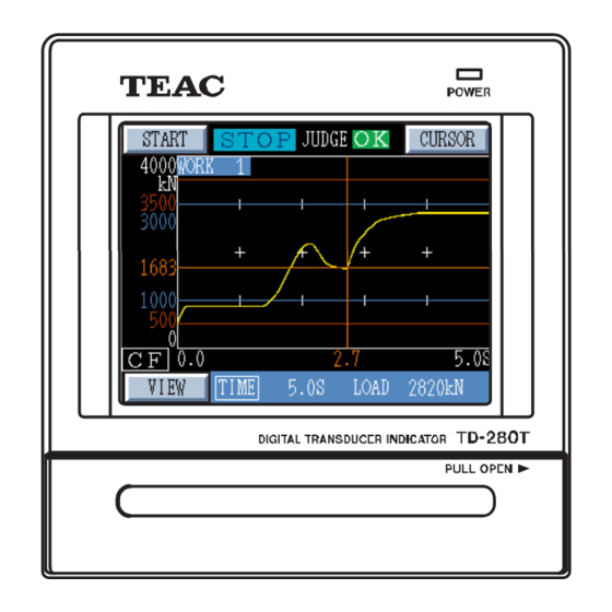
1-1-2 Graph Display Screen Start button Cursor button Graph range Load HI-HI limit value Load HI limit value Judged load value Load LO limit value Load LO-LO limit value Graph range Disp. HI limit value Disp. display Change measuring Judged disp. value Change view button Display Disp. -
Page 16: Display Of Operation Panel
1-1-3 Display of Operation Panel TD-280T is equipped with the touch panel LCD display for initializing sensors or performing various operations. On this panel, the setting selection display, the strain display, the graph display, or other can be selected. Settings screen... -
Page 17: Rear Panel
・ The provided AC power cord is only intended for use within Japan, rated for 10 A at 125 V AC. If you want to use the TD-280T at a voltage exceeding the specified voltage or overseas, be sure to use another AC power cord that is more appropriate for your operating ・... -
Page 18: Sensor Signal Input Connector
1-2-5 Sensor Signal Input Connector Strip about 5 mm of insulation off each signal wire and lightly twist the bare wire to fit the terminal hole. Use a mini screwdriver to connect the wires. Applicable wire is 1.5φ or less (AWG 28 – 16). Pull the connected cable lightly and check that the cable is securely clamped. -
Page 19: Control Signal Input/Output Connector
1-2-6 Control Signal Input/Output Connector In/Out Signal Name In/Out Signal Name Load Digital Zero Work Select 1 Displacement Position Adjustment Work Select 2 (Preset) Measurement Start/Stop Work Select 3 Hold Command (Displacement) Work Select 4 Hold Command (Load) External Judgment Reset Reset Signal COM -... - Page 20 A5 : Hold Command (Load) Functions as a load value hold timing contact signal. During “Sample Hold”, holds and determines the load value at the ON timing. However, when a signal makes an ON-OFF-ON transition, the load value is held at the first ON timing of the measurement.
-
Page 21: Input Signal Timing
B14 : Load Normal Turns OFF when errors associated with load cells, such as digital zero limit, sensor errors, or display value overflow, are detected. B10 : Differential Pulse Output Displacement Sensor: Phase A- Phase A- of a differential pulse output displacement sensor. This also functions as input for one-phase. -
Page 22: Connection
For 6-wire load cell, short-circuit +EXC with +SENSE and -EXC with –SENSE; and connect to terminal No.3 (+EXC) and terminal No.5 (-EXC). 2-2 Connecting TEDS Memory TD-280T You need to connect TEDS memory to TD-280T when using a TEDS sensor. ←Inside Outside→... -
Page 23: Connecting Voltage Output (V-Out)
Connect a differential square-wave output type displacement sensor. Displacement sensor ←Inside Outside→ TD-280T receives the differential output (RS422 level) + signal from the sensor and converts it to a TTL level. Phase A - Pin No. A7 (+5 V power supply) provides 500 mA +... - Page 24 ◇ Internal count for pulse sensor output TD-280T has two modes for the output signal of a pulse displacement sensor. In one mode, only the phase A is counted, and in the other mode, the phases A, B (two-phase signal) are counted.
- Page 25 Set the pulse and the display value in the Pulse equiv. input cal screen in accordance with the specifications of your sensor. Pulse equiv. input cal screen ◇ Connecting external signal for displacement sensor The external control signal inputs for a displacement sensor TD-280T are as follows. Preset ←Input Output→...
-
Page 26: Connecting Control Signal Input/Output
+5V power supply is electrically isolated TTL open collector from TD-280T internal power supply ON when IN is ‘H’ Because a current of approx. 8 mA flows into the external contact when it is turned ON, use a contact element which withstands 10 mA or more. -
Page 27: Setting Mode Configuration
3. Setting Mode Configuration 3-1 Screen Configuration Graph display screen Digital display screen (TOP screen) Settings screen From “WORK INPUT” and "HIGH “ “HI LOW LIMT” From “DETAIL SET” Detail settings screen Meas. display (COMMON) screen To Graph range, Grid settings, Strain display, etc. - Page 28 3-2 Hierarchy of Setting Screens Settings HI LO Limit Detail settings Meas. display (COMMON) Graph range Grid settings Grid settings Strain display Graph horizontal axis Graph data select Analysis settings WORK settings Operating condition 1 Measuring start Measuring start load Measuring start disp.
-
Page 29: Calibration Of Sensor
It is a calibration method using the data stored in a TEDS memory in which the rated output value (mV/V) and the rated capacity of a strain gage sensor are recorded. Two types of TEDS-compatible memories are available: 1 kBit and 4 kBit. TD-280T supports only 4 kBit memory. - 28 -... -
Page 30: Before Calibration
4-2 Before Calibration ◇ Setting bridge voltage Set a bridge voltage in accordance with the specifications of a strain gauge sensor. Note that selecting an incorrect bridge voltage may damage the sensor. From the TOP screen, select “SETTINGS”→“DETAIL SET”→“SENSOR CAL.”→“LOAD-CELL”→“BV” to set a bridge voltage. -
Page 31: Equivalent Input Calibration
Pushing on the Load sensor 1 screen advances to the Load sensor 2 screen, and pushing on the Load sensor 2 screen returns to the Load sensor 1 screen. Load sensor 1 screen Load sensor 2screen Prior to each calibration, select “ZERO BAL” on the Load sensor screen to perform zero adjustment. Be sure to perform the zero adjustment to record an initial zero point of a connected sensor. -
Page 32: Teds Calibration
When read is completed, the rated output of the sensor as well as display value (rated capacity) and its unit are displayed on the screen. Then push the “UPDATE" button to complete the calibration. Caution) You need to connect a TEDS-capable sensor to TD-280T if performing TEDS calibration. - 31 -... - Page 33 In TEDS calibration, TD-280T displays rated capacity values as shown in the table below. The TEDS calibration data is stored in TD-280T. Thus, if any changes to display values are required after the calibration is performed, return to the Equivalent input calibration screen and change the value of “DISPLAY” and its decimal point position.
-
Page 34: Selecting Load Unit
4-3-1-4 Selecting Load Unit From the Load sensor 1 screen, select “UNIT.” Set the unit of load. Available settings: N, kN, g, kg, kPa, MPa, Nm, or NONE. Load unit screen 4-3-1-5 Adjusting Zero Point From the Load sensor 1 screen, select “ZERO BAL.” Be sure to perform the zero adjustment to record an initial zero point of a connected sensor. -
Page 35: Setting Digital Offset (Tare)
4-3-1-7 Setting Digital Offset (Tare) From the Load sensor 2 screen, select “DIG. OFFSET.” The digital offset function displays a value obtained by subtracting a set digital offset value from a measured value. This function is disabled for the real load calibration. INVALID : The digital offset function is disabled. - Page 36 4-3-2-1-1 Equivalent Input Calibration From the Voltage cal screen, select “EQUIV. INPUT.” Enter the amount of displacement (mm) and a rated output (voltage) based on the data sheet of the connected displacement sensor. Next, enter a rated capacity on the entry screen based on the data sheet of the sensor as well.
-
Page 37: Setting Pulse Output Displacement Sensor
4-3-2-2 Setting Pulse Output Displacement Sensor From the Displacement sensor screen, select “SETTINGS” next to “DISP. PULSE.” Like load sensors, equivalent input calibration and real load calibration are available. Equiv. Input (Equivalent input calibration): Enter the pulsed quantity associated with the amount of displacement based on the data sheet of the connected sensor. -
Page 38: Setting Displacement Unit
COUNTER: The internal 16 bit counter can count from 0 to 65535. However, in some cases, a count value may be as high as 65535 or more, or may be as low as 0 or less. To maintain effective balance between them, position the center of the sensor at 32767. -
Page 39: Setting Measuring Time
4-3-3 Setting Measuring Time From the Sensor calibration screen, select “TIME.” Measuring time is set along the time axis (horizontal axis) of the graph display screen. A measuring time of 0.1 to 30.0 seconds can be set. A set time serves as the maximum time (from the start of measurement). Set the maximum measuring time in the Meas. -
Page 40: Sensor Settings
5. Sensor Settings Determine detail settings for load and displacement sensors. The Load sensor screen allows you to determine settings for a minimum scale value, digital/analog filters, constant judgment, a zero limit value, and load color display. The displacement sensor screen allows you to determine settings for analog and digital filers. -
Page 41: Zero Limit Settings
5-1-2 Zero Limit Settings From the Load sensor screen, select “ZERO LIMIT.” Specify a range where the “DZ” (Digital Zero) function is effective. The Digital Zero function performs comparison based on the load value set in “ZERO BAL” on the Load sensor 1 screen (accessible from the Sensor calibration screen). -
Page 42: Load Value Color Display Settings
H_H/L_L limits and HI/LO limits are always output. After a value is held, results obtained by comparing the held value with the load H_H/L_L limits and HI/LO limits are always output. If you select “MULTIPLE”, “INF.TRG”, or “MANY” on the Hold Select screen, stable judgment is disabled. -
Page 43: Analog Filter Settings
5-2-1-1 Analog Filter Settings From the Voltage disp. sensor screen, select “ANALOG FLT.” This analog filter has a cutoff frequency of 10Hz, 30Hz, 100Hz, or 300Hz, and is connected upstream of the A/D converter. When necessary, such as when displacement values are unstable, select an appropriate frequency. -
Page 44: Type Settings
5-2-2-2 Type Settings From the Pulse disp. sensor screen, select “TYPE.” Specify the type of differential pulse output displacement sensor. A : Select for one-phase sensors. A・B: Select for two-phase sensors. Sensor type screen Note: - 43 -... -
Page 45: Measurement Display Settings
6. Measurement Display Settings From the TOP screen, select “SETTINGS”→“DETAIL SET”→“VIEW.” The Meas. Display (COMMON) screen allows you to determine settings for “GRAPH SET.”, “GRID”, and “STRAIN.” Meas. display (COMMON) screen 6-1 Graph Range Settings From the Meas. display (COMMON) screen, select “GRAPH SET.” Set the graph range. -
Page 46: Strain Display
The screen allows you to check the load sensor, and displays signals from the load sensor in units of the amount of strain. It is recommended that you note down the strain value shown in “Strain display” when integrating TD-280T with your system. -
Page 47: Analysis Settings
Caution) To set displacement, from the TOP screen, you must select “SETTINGS”→“DETAIL SET”→“SENSOR SET.”→“DISP.” and then select either “DISP.VOLT” or “DISP.PULSE” to enable displacement. 6-5 Analysis Settings When HOLD is INF.PNT, the inflection point is at the peak of load difference. But, from the load-time curve shown in the indicator, it is difficult to determine and set the load difference. - Page 48 ◇ Scaling the axis of the load difference graph The load difference is scaled relative to a maximum load difference. It is automatically set to a maximum load difference times ±1.25. Caution) the load difference is calculated after the load exceeds the detection start load value. Therefore, the load difference may not exist on the origin point along the horizontal axis.
-
Page 49: Work Settings
7. Work Settings 7-1 Setting Work and Switching to a Different Work To select a work number and set the work, select “SETTINGS” →”DETAIL SET”→“WORK.” Set the operating condition for each work number. Work settings allow you to program a maximum of 16 operating conditions. Work settings screen To switch to a different work, select “SETTINGS”→”WORK INPUT”... -
Page 50: Measuring Start Condition Settings
7-2-1 Measuring Start Condition Settings From the Operating condition screen, select “MEAS. START.” As a measuring start condition, select “START SIGNAL” (the START button on the screen or an external measuring start/stop signal), “START+LOAD”, or “START+DISP.” START SIGNAL: Measurement is started through a start signal (when the START button on the screen or an external measuring start/stop signal is turned ON). - Page 51 signal is turned OFF). STOP+DISP. : Measurement is stopped through a stop signal or when the following conditions are met (OR condition). Measurement is stopped differently depending on which setting (measuring start displacement or measuring stop displacement) is large (The value set in “LOAD SET.” on the “Measuring start”...
- Page 52 ◇ Stopping Continuous Measurement Continuous measurement can be stopped in the following ways: ・ Turn OFF the external measuring start/stop signal. ・ When the continuous measurement is started through the START button, push the START button again. ◇ Switching to a Different Work Number during Continuous Measurement When you select “STOP+CONT.”, you can switch to a different work number for each measuring time.
-
Page 53: Measuring Time Settings
7-2-3 Measuring Time Settings From the Operating condition screen, select “MEAS. TIME” to set the maximum measuring time. COMMON : The measuring time which is set by selecting ”SETTINGS”→“DETAIL SET”→“SENSOR CAL.”→“TIME” from the TOP screen is applied. BY WORK : The measuring time which is set by using the “SETTINGS” button in the Measuring time screen is applied. - Page 54 DISP.SMP : Holds the displacement value when an external “hold (displacement)” signal is turned ON during a measuring period. If a signal makes a continuous ON/OFF transition during a measuring period, the displacement value at the first ON transition is held. MULTIPLE : According to the hold conditions set by choosing “MULTIPLE”...
-
Page 55: Sample Hold
7-2-4-1 Sample Hold Holds the load value at a certain point when the hold command signal (external A5 signal pin) is turned ON during a measuring period. Compares the held load value against the HI LO limits and HI_HI LO_LO limits and outputs the judgment result. The limits are set as discussed in “7-2-5-1 Setting the Load Limits.”... -
Page 56: Peak Hold
7-2-4-2 Peak Hold Holds the maximum load value obtained during a measuring period. Compares the peak held load value against the HI LO limits and HI_HI LO_LO limits and outputs the judgment result. The limits are set as discussed in “7-2-5-1 Setting the Load Limits.” From the TOP screen, select “SETTINGS”→”DETAIL SET”→“WORK”... -
Page 57: Inflection Point Hold
7-2-4-3 Inflection Point Hold Captures the change of the slope of the load value during a measuring period and holds the value. Compares the load value held at the inflection point against the HI LO limits and HI_HI LO_LO limits and outputs the judgment result. - Page 58 ◇ Detection of Inflection Point In the Inflection point screen, set the load difference E, detection time A, detection time B and detection start load value. START : Set a start load value from which the inflection point detection is started.
-
Page 59: Maximum/Minimum Value Hold
7-2-4-4 Maximum/Minimum Value Hold Holds the load value at the moment when the maximum or minimum value is attained during a measuring period. Compares the held load value against the HI LO limits and HI_HI LO_LO limits and outputs the judgment result. The limits are set as discussed in “7-2-5 Setting the Limits.”... - Page 60 ◇ Maximum and Minimum Settings When you select the “Max, Min” button on the Hold settings screen, the Maximum, Minimum select screen is displayed. Select “MAXIMUM” to set the maximum hold mode, or “MINIMUM” to set the minimum hold mode. Then, determine the following settings.
-
Page 61: Displacement Peak Hold
7-2-4-5 Displacement Peak Hold Holds the maximum displacement value obtained during a measuring period. Compares the load value peak held at the displacement value against the HI LO limits and HI_HI LO_LO limits and outputs the judgment result. The limits are set as discussed in “7-2-5 Setting the Limits.” To use the displacement peak hold mode, it is necessary to select “DISP.VOLT”... -
Page 62: Displacement Hold
7-2-4-6 Displacement Hold Holds the load value at the moment when the displacement value set is attained during a measuring period. Compares the load value held at the displacement value against the HI LO limits and HI_HI LO_LO limits and outputs the judgment result. - Page 63 Enter a displacement comparison value, specified in millimeters (mm). Set values by using the key to place the cursor over a digit you want to change, and using the key to set a desired value, and then push the “Update” button to confirm. Displacement settings screen Note: - 62 -...
-
Page 64: Displacement Sample Hold
7-2-4-7 Displacement Sample Hold Holds the load value at a certain point when the hold (displacement) signal (pin 10 of STROKE connector) is turned ON during a measuring period. Compares the held displacement value against the HI LO limits and HI_HI LO_LO limits and outputs the judgment result. -
Page 65: Multiple Hold
7-2-4-8 Multiple Hold This hold is set when using multiple-zone judgment. In multiple-zone judgment, judgment ranges (zones) of either load and time or load and displacement are set and judgment about whether a hold value falls within the zones is made. Up to 3 zones can be set, and each can contain different hold conditions. - Page 66 In the Multiple hold screen, select the hold condition for zone judgment. Available settings: “NONE”, ”SAMPLE”, ”PEAK”, ”INF.PNT”, ”MAX, MIN”, ”DISP.PK”, ”DISP.”, or “DISP.SMP”. If “NONE” is set in the Multiple hold screen, the zone is not subject to the judgment. For the zone which is set to “NONE”, leave Multiple hold screen unselected in the Criterion settings (“ZONE...
-
Page 67: Inflection Point Trigger Peak Hold
7-2-4-9 Inflection Point Trigger Peak Hold Captures the change of the slope of the load value during a measuring period, detect the inflection point and holds the preceding peak hold value. Compares the peak load value held against the load HI LO limits and outputs the judgment result. The limits are set as discussed in “7-2-5-1 Setting the Load Limits.”... - Page 68 ◇ Hold settings for inflection point trigger peak From the Hold settings screen, select “INF. TRG” to display the Inf. Point trigger screen, in which you determine settings for “ANALYSIS”, “INF. POINT” and “OPTION.” Inf.point trigger screen ◇ Analysis settings Set the conditions for detecting a peak load value preceding the inflection point.
- Page 69 Set values by selecting an item (“A” is selected in the figure on the left), using key to place the cursor over a digit you want to change, and using the key to set a desired value, and then push the “Update”...
-
Page 70: Many-Point Hold
7-2-4-10 Many-Point Hold Captures the change of displacement during a measuring period, based on the base point and offset values defined for displacement, and holds the hold value at the defined offset position (up to a maximum of 5 points for offset values). For each offset, compares the held load value against the load HI LO limits and outputs the judgment result. - Page 71 Example of many-point hold when “Base point” is ”PEAK” Offset 1‐5 Displacement Displacement base point Load Measuring start load value Time Measuring period ◇ Many-Point Hold Settings From the Hold settings screen, select “MANY” to display the Many settings screen, in which you determine settings for “BASE POINT” and “OFFSET.” Many setting screen ◇...
-
Page 72: Setting The Limits
In the Offset length screen, set the length of displacement offsets (X1 to X5) from the base point. Set values by selecting an item (“X1” is selected in the figure on the left), using key to place the cursor over a digit you want to change, and using the key to set a desired value, and then push the “Update”... -
Page 73: Setting The Load Limits
7-2-5-1 Setting the Load Limits Load limits settings are different, depending on whether “MANY” hold is set or not. ◇ When a hold other than “MANY” is set Load detection function allows you to specify HI/LO limits and HI_HI/LO_LO limits. In the HYSTERESIS SETTING screen, you can set the width of hysteresis. - Page 74 When you set a value other than 0.0 in “HYS”, the hysteresis function becomes effective. ・ Once the HI judgment output becomes ON, the state continues until a measured load value falls below a value obtained by subtracting the hysteresis value from the HI limit value. ・...
-
Page 75: Setting Displacement Limits
◇ Judgment output for many-point hold values Many-point hold values are judged against the set load HI and LO limit values and displacement HI and LO limit values and the result is output as follows. Judging condition Displacement Load judgment judgment output output for selected offset, load hold value, displacement peak value and load... -
Page 76: Multiple-Zone Limit Value Settings
◇ Shortcut to HI and LO limit value setting To set load and displacement HI and LO limit values, usually access the TOP screen → “SETTINGS”→ “DETAIL SET”→“WORK” →“Work No.” (1 to 16)→“CRITERION”→“LOAD” or “DISP.” - “SET”. Alternatively, you can use “SETTINGS” →“HI LO LIMIT”as a shortcut. The settings can be changed only when load or displacement is judged. - Page 77 Setting conditions Load Load LO:Y1, Load HI:Y2 Displacement LO:X1, Displacement HI:X2 (X2,Y2) In this case, The settings are independent between the zones, but X1 ≤ X2 and Y1 ≤ Y2 are required within the zones. (X1,Y1) Disp. For multiple-zone judgment, “NONE” or “MULTIPLE” hold can be set. When “NONE”...
- Page 78 ◇ Example of Multiple-zone Judgment (Hold Condition: MULTIPLE) The figure on the left shows an example of a multiple-zone judgment graph before measurement is performed. In this case, three zones are set. Multiple-zone judgment checks whether hold values falls within the determined zones.
- Page 79 ◇ Details of Multiple-zone judgment result Details of multiple-zone judgment result and settings can be checked by pushing the DETAIL button on the digital display screen (TOP screen). Push the “DETAIL” button on the digital display (TOP screen) to display the Judgment result detail screen.
-
Page 80: Special Judgment Output
7-2-5-4 Special Judgment Output ◇ Judgment NG output When comparing and judging hold values, comparison output (HH, HI, GO, LO, LL) may not be applied. This case is called “judgment NG,” and can be output by assigning to the HI and LO signals for comparison outputs. Usually, for judgment NG, comparison output (HH, HI, GO, LO, LL) is not changed, and therefore judgment NG can not be detected from comparison output. -
Page 81: Measuring Display Settings
7-2-6 Measuring Display Settings Set the measuring display conditions. From the TOP screen, select “SETTINGS”→”DETAIL SET”→“WORK” →“Work No.”(1 to 16)→“MEAS. DISP.” COMMON : The settings defined by choosing ”SETTINGS”→“DETAIL SET”→“VIEW” from TOP screen is applied. BY WORK : The measuring display set by using the “SETTINGS” button in the Meas. -
Page 82: Cf (Compact Flash) Settings
8. CF (Compact Flash) Settings The CF screen allows you to determine settings for storing onto a compact flash card. From the TOP screen, select “SETTINGS”→”DETAIL SET”→“CF.” When recorded data is stored, the filename (if date is set) and timestamp are generated based on the system clock. Make sure that the system clock is accurate. -
Page 83: Filename Settings
When you select “STORE”, the recorded data is stored on the CF card. Once the store has been finished, the filename is displayed. Push “OK” to confirm. Caution) The CF mark is displayed to indicate that a CF card is inserted. During the CF card is being accessed, the CF mark is shown in yellow. -
Page 84: Remaining Alert And Limit Settings
Example: If 6000 files are recorded under Work No. 2, the files are saved under two different folders as follows: to 5000 files ¥WORK2¥TD001¥TD0001.CSV to TD5000.CSV 5001 to 6000 files ¥WORK2¥TD002¥TD0001.CSV to TD1000.CSV If more than one measurement was performed in one second or less, select “COUNT.”... -
Page 85: Decimation
“2 k.” Decimation screen 8-5 Saving a Setup File From the CF screen, select “SAVE SETTING.” Various setting information of TD-280T is saved in a setup file (TD-CNF.PRM) on a CF card. Filename: TD_CNF.PRM Target directory: ¥ (root directory) CF Save settings screen When you push “Save”... -
Page 86: Loading A Setup File
After determining the settings for sensor calibration, load the settings. ・ It is recommended to use a setup file with the same version of firmware currently installed in TD-280T. Using firmware with a different version can lead to errors because of the difference in specifications. -
Page 87: Installing And Removing A Cf Card
Make sure that the LED indicator, located to the right of the CF card slot, goes up. d) Close the CF card slot cover on the front panel. When a CF card is recognized by TD-280T, a CF mark is displayed on the screen. When a CF card is inserted, a CF mark is displayed. -
Page 88: File Erase And Format
To erase files stored on the CF card or format the CF card, use your PC. You can not erase files stored on the CF or format the CF card directly from TD-280T. If the CF card is full, use another new CF card or erase the files stored on the CF card or format the card. -
Page 89: System Settings
9. System Settings The System settings screen allows you to determine settings for the backlight and contrast of the LCD, the backlight timer, check of external IN/OUT signals, the clock, the system information, the buzzer, key lock, judgment NG output, system reboot, and optional board (if installed). -
Page 90: Initializing Settings
9-3 Initializing Settings From the System settings 1 screen, select “INITIALIZE.” This function is used to reset various settings of TD-280T to their defaults. System initialize screen Push the “INITIALIZE” button on the System initialize screen and then push the “OK”... -
Page 91: Backlight Off Timer Settings
9-6 System Information From the System settings 2 screen, select "SYSTEM INFO." This should display various version and configuration information for your TD-280T. When you contact us for help, you may need to provide the system information. System information screen... -
Page 92: Buzzer Settings
9-7 Buzzer Settings From the System settings 2 screen, select “BUZZER.” Specify whether or not the buzzer sounds when pushing on the touch panel. INVALID : The buzzer does not sound. VALID : The buzzer sounds. Buzzer settings screen 9-8 LANG (言語) Select which language you want to use: Japanese or English. -
Page 93: Judgment Ng Output
9-10 Judgment NG Output When comparing and judging hold values, comparison output (HH, HI, GO, LO, LL) may not be applied. This case is called “judgment NG,” and can be output by assigning to the HI and LO signals for comparison outputs. Usually, for judgment NG, comparison output (HH, HI, GO, LO, LL) is not changed, and therefore judgment NG can not be detected from comparison output. -
Page 94: Settings When An Optional Board Is Installed
◇ Option settings The option settings are enabled only when an optional board is installed in the option slot provided on the back of TD-280T. Select “SETTINGS”→”DETAIL SET”→“SYSTEM.” When an optional board is installed, a button for setting the option appears. -
Page 95: Output Adjustment
10-1-1 DA Output Adjustment From the DA settings screen, select “ADJUST” to adjust DA output. The DA output adjust screen allows you to set load values at DA zero and at DA full scale. Set values by selecting an item (“ZERO” is selected in the figure on the left), using the key to place the cursor over a digit you want to change, and using the... -
Page 96: Voltage And Current Output Connections
・ Connect an external device (with a load resistance of 2 kΩ or more) to the "V"+ (plus) and the "V"- (minus) for voltage output. ・ Connect an external device to the "I"+ (plus) and the "I"- (minus) for current output. TD-280T ←Inside Outside→... -
Page 97: Setting Rs-232C Interface
RS-232C interface is used to read out the indicated values or recorded data from TD-280T. It is useful when connecting TD-280T with a computer, a process controller or a sequencer, etc. to perform tasks such as control, aggregation, recording, etc. -
Page 98: Parity Settings
10-2-3 Parity Settings From the RS-232C settings screen, select “PARITY” to set a communication error detection code. Available settings: None, Odd, or Even. Parity setting Screen 10-2-4 Communication Specifications ◇ Standard Signal level : Based on RS-232C Transmitting distance : Approx. 10 m Transmitting method : Asynchronous, Full duplex Transmitting speed... - Page 99 ◇ Cable connection sample Cross cable connection sample D-Sub D-Sub RS-232C 9-pin 25-pin option female male SHELL SHELL Note: - 98 -...
-
Page 100: Communication Format
10-2-5 Communication Format Request is a command sent from a host computer to TD-280T and Response is data sent from TD-280T to a host computer. All characters are ASCII, except [CR] and [LF]. ([CR]:Carriage Return (0x0D)、[LF]:LineFeed (0x0A)) Request S C A N... - Page 101 Communication speed On a transmission of load and displacement, C54 or beyond requires a communication speed of 19200 bps or more. Processings when the transmission is stopped by flow control When the transmit buffer has enough free space, the current value is written into the transmit buffer. After the transmit buffer is full, the current value is not written into the transmit buffer.
- Page 102 ◇ TR_ACQ_DAT command Function : To acquire the recorded data Argument : none Data is transmitted as characters (ASCII) BIN Data is transmitted as binary (float) BIN_S Data is transmitted as binary (short) Description ・ When no argument is specified, the recorded data is transmitted as characters. Order in which data is transmitted the number of data per line, the number of lines transmitted Measurement data...
- Page 103 ◇ VERBOSE command Function : To set how the status is transmitted Argument : Mode 0 or 1 Description When Mode 0 is specified, !ACQ_START and !ACQ_END messages are not returned. When Mode 1 is specified, !ACQ_START and !ACQ_END messages are returned. When no argument is specified, the VERBOSE mode setting (0 or 1) and OK are returned.
- Page 104 ◇ ACQ_RESET command Function : To reset the measurement status Argument : none Description The command is effective only when the measurement screen is displayed. The command is equivalent to pushing the RESET button on the screen where the measured values are displayed.
-
Page 105: Overscale/Error Displays
11. Overscale/Error Displays This section describes overscales and errors which may be displayed on each screen. 11-1 Errors Related to Load Sensor LOAD: This error indicates that an input signal from the load sensor exceeds +3.0 mV. It also indicates that a sensor signal exceeds 3.0 mV/V. The sensor and the cables require to be checked. -
Page 106: Errors Related To Displacement Sensor
11-2 Errors Related to Displacement Sensor FULL: This error appears when a displacement value is positive and is too large to fit within the number of digits allowed available on the display. For example, suppose that a value is displayed to one decimal place. In this case, a larger value than 999.9 causes this error. -
Page 107: Errors During Load Sensor Calibration
11-3 Errors During Load Sensor Calibration ◇ Errors during real load calibration Input-range over error This error shows that the signal from the sensor exceeds the input range (3 mV/V) of the indicator. This 3 mV/V includes the zero point of the sensor. Input-range over error screen Zero balance error This error shows that during zero point measurement, the signal from the... -
Page 108: Hardware Installation
Guide rail 3.Push the TD-280T into the panel cut-out area from the front side of the panel. 4. Put the guide rails that were removed in Step 2, back in place from the rear side, and then secure them with the two screws. -
Page 109: Specifications
13. Specifications Load Sensor Input 1) Input/Range : Strain gauge sensor ±3.0 mV/V Input connector : Screw connection-type terminal (pitch 5.08 mm, 12P) 2) Excitation Voltage : 2.5 V DC (±10%)/10 V DC (±10%) Current: 30 mA 3) Calibration method : Equivalent Input/TEDS/Real Load Calibration range : 0.5 to 3.0 mV/V... - Page 110 Common Section 1) Display/Operation : 3.5 inch STN color LCD model (320×240 dot) Operation : Touch panel Load display range : 0 to ±9999 Decimal point : Selectable display position Display timing : 3 times/sec. Time axis setting : 0.1 to 30.0 sec. 2) Indication items : Digital load value, Waveform, Setting, Distortion, etc.
- Page 111 9) Ambient Temperature/Humidity Temperature : Operation 0 to +40℃ Storage -20 to +60℃ : ≤85%RH (Non-condensing) Humidity 10) Dimension (W×H×D) : Approx. 105 mm×108 mm×145.1 mm 11) Weight : Approx. 1.05 kg 12) Accessories : Instruction Manual (CD-ROM) Brief Instruction Manual Sensor input connector Phoenix Contact MC1.5/12-STF-5.08 Control input/output connector/plug (FUJITSU)
-
Page 112: Dimensions
14. Dimensions +0.5 92 0 Panel cutout dimensions パネルカット寸法 * Recommended board thickness: 1.6 to 3.0 mm ※推奨板厚:1.6mm~3.0mm 23.6 (推奨板厚範囲以外は別途相談下さい。) (Please consult us regarding other baord thicknesses.) SERIAL NO. MADE IN JAPAN (17 .5) 91 105 24.1 (121)...
Need help?
Do you have a question about the TD-280T and is the answer not in the manual?
Questions and answers