
Related Manuals for Teac LX Series


Summary of Contents for Teac LX Series
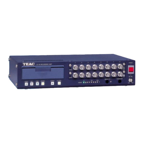
- Page 1 RECORDING UNIT LX Series Instruction Manual Please read this manual before using the product, and keep the manual handy. TEAC Corporation May 2006 D00634900D...
- Page 3 SAFETY INSTRUCTIONS CAUTION: Read all of these Instructions. Save these Instructions for later use. Follow all Warnings and Instructions marked on the product. 1) Read instructions -- All the safety and operating instructions should be read before the product is operated. 2) Retain instructions -- The safety and operating instructions should be retained for future reference.
- Page 4 SAFETY INSTRUCTIONS 17) Damage Requiring Service -- Unplug this product from the wall outlet and refer servicing to qualified service personnel under the following conditions: a) when the power-supply cord or plug is damaged. b) if liquid has been spilled, or objects have fallen into the product. c) if the product has been exposed to rain or water.
- Page 5 Wohnbereich Funkstörungen versursachen ; in diesem Fall kann vom Betrieber verlang werden, angemessene Maßnahmen durchzuführen und dafür aufzukommen. DISCLAIMER TEAC disclaims all warranty, either expressed or implied, with respect to this product and the accompanying written materials. In no event shall TEAC be liable for any damages whatsoever (including, without limitation, damages for loss of business profits, business interruption, loss of business information or other loss) arising out of the use of or inability to use this product.
- Page 6 2. COPYRIGHT All title and copyrights in and to the SOFTWARE and any copies thereof are owned by TEAC or a supplier to TEAC. The SOFTWARE is protected by Japanese copyright laws, international treaty provisions, and all other applicable national laws.
-
Page 7: Table Of Contents
Installation Connections Notes on Connections PC System Requirements Installing LX-10/20 IEEE 1394 Version Installing Interface Card Installing OHCI Driver Installing LX Series Device Driver Installing LX Navi 2-15 Installing LX-10L/20L LAN Version 2-16 Installing LX Navi 2-16 About IP Address Settings... - Page 8 Contents Saving Settings 4-25 Loading Settings 4-26 Section 5 Operations Specifying Recording Devices and File Names Recording to Memory Recording to Media (MO/PC Card) Recording to PC Recording Operations Exchanging Media 5-10 Copying 5-11 Reproducing 5-12 Reproducing Operations 5-13 Moving Reproducing Point (Skip) 5-13 Searches 5-14...
- Page 9 Contents Section 7 Appendixes Troubleshooting Supplied Accessories and Options Supplied Accessories Options...
- Page 10 Contents viii...
-
Page 11: Preface
Section 1 Preface Overview ............. Features .............. About TAFFmat ............ Notes on Usage ..........Names and Parts ..........Front .............. Rear ............... 1-10 Recording Times ..........1-12 Sampling Frequency and Number of Channels ..1-13... -
Page 12: Overview
Overview Overview The LX series instrumentation data recorders can record and reproduce signals of a maximum 48 kHz sampling frequency via 8 channels onto MO (Magneto Optical Disk) or PC card media. Recorded data on the media is stored as PC files. The maximum input channels are 32 channels by using the selectable types of the 8 channels input cards and the optional channel expansion unit. -
Page 13: Features
Features Features Input/Output Amps The LX main unit equips 2 slots and the optional expansion unit provides additional 2 slots for installing the input amps and/or the output amps. The input/output amp provides 8 channels inputs/outputs from the below selections. DC input amp card: Use to connect voltages and/or to connect signals of external amplifiers. - Page 14 Features A Variety of Recording Triggers Manual: Starts recording manually. Level Trigger: Starts recording by detecting level changes in a specified channel. External Trigger: Starts recording by using an external signal as the trigger. Pre-trigger: A pre-trigger can record the data that was read into a buffer before a recording-startcondition (based on a level trigger or external trigger) was satisfied.
-
Page 15: About Taffmat
-> second sampling channel order ->...-> last sampling channel order. At the LX series, ADC value +/- 25000 represents +/- 100 % of the input range. This document uses the term scan to refer to a collection of data resulting from one sampling. A data file is a collection of scan repetitions. -
Page 16: Notes On Usage
Use Specified Media Only Use 1.3 GB, 3.5 inch MO disks from Fujitsu Ltd. Use PC cards checked by TEAC in advance (contact us for information). Other media might be unable to record or reproduce correctly. PC Cards Checked by TEAC for Correct Operations (As of August 2005) - Page 17 Notes on Usage Clean Disk and Lens Dust might collect on an MO disk or lens after they have been used for a long time. This dust might cause errors. To prevent this problem, clean the MO disk and lens using a cleaning kit (separate purchase). The period after which cleaning is required depends on the environment but, as a general rule, clean once every three months.
-
Page 18: Names And Parts
Names and Parts Names and Parts Front Drive Opening the cover reveals the disk slot. Input level LED When the input signal for some channel is larger than +/- 10 % of a set input range, the LED glows green. - Page 19 Names and Parts Output connector (When the analog playback amp card is installed into the slot.) Outputs the reproduced signal. Outputs the input signal during recording-standby status or during recording. You can set the output range in 0.1 V steps, from 1 V to 5 V. Output level LED (When the analog playback amp card is installed into the slot.) When the output signal for some channel is larger than +/-10% of a set output range, the LED glows green.
-
Page 20: Rear
Names and Parts Rear LX-10 IEEE 1394 Version SE RI A L N O. M AD E IN JA P AN The LX-10L LAN version has an interface (at 7) shown below. LX-20L LAN Version L A N SERIAL NO. R... - Page 21 Names and Parts FG terminal Connects the grounding wire. MON OUT connector Outputs in analog format, the signal of a channel during recording-standby status, recording, or reproduction. You use the supplied LX Navi software to select the channel you want to monitor. You can set the output range in 0.1 V steps, from 1 V to 5 V.
-
Page 22: Recording Times
Recording Times Recording Times Recording to Memory, 8 channels, 64 MB standard memory (when not recording voice memos) Sampling frequency(Value in brackets is the recording Recording time bandwidth with tolerances of +/-0.5 dB) 96 kHz (40 kHz) 40 s 48 kHz (20 kHz)... -
Page 23: Sampling Frequency And Number Of Channels
Sampling Frequency and Number of Channels Sampling Frequency and Number of Channels A combination of the sampling frequency vs. the number of analog input channels is varied depending on the selected recording mode, such as, the type of the recording media and the number of tachometer input channels. - Page 24 Sampling Frequency and Number of Channels Recording Condition 2 Recording Mode: Memory recording Memo Voice Recording: ON or OFF Interface to PC: IEEE1394 or Ethernet 102.4 kHz Series Max. number of analog input channels based on the tachometer input setting Sampling Frequency (kHz) Bandwidth (kHz) 16bits 2ch...
- Page 25 Sampling Frequency and Number of Channels Recording Condition 3 Recording Mode: PC direct recording Memo Voice Recording: ON or OFF Interface to PC: IEEE1394 102.4 kHz Series Max. number of analog input channels based on the tachometer input setting Sampling Frequency (kHz) Bandwidth (kHz) 16bits 2ch 32bits 1ch...
-
Page 26: Sampling Frequency And Number Of Channels
Sampling Frequency and Number of Channels 1-16... - Page 27 PC System Requirements ................ Installing LX-10/20 IEEE 1394 Version ............Installing Interface Card ................. Installing OHCI Driver ................Installing LX Series Device Driver ............Installing LX Navi ................... 2-15 Installing LX-10L/20L LAN Version .............. 2-16 Installing LX Navi ................... 2-16 About IP Address Settings ...............
-
Page 28: Connections
Cannot connect with PC at a time. Connect to PC IEEE 1394 interface (Either is available. Use TEAC recommended IEEE 1394 interface card for PC.) (LX-10/20) When the DC power voltage falls to +11V or less, the USAGE LEDs flash and recording and reproduction stops. -
Page 29: Notes On Connections
Connections Notes on Connections Attaching Ferrite Core on IEEE 1394 Interface cable (LX-10/20 IEEE 1394 version) To reduce the radio noise, attach the supplied ferrite cores on both ends of the IEEE 1394 cable. Only PC to IEEE 1394 Connector (LX-10/20 IEEE 1394 version) Do not connect other devices than the PC to the IEEE 1394 connector. -
Page 30: Installing Lx-10/20 Ieee 1394 Version
Follow the installation procedures explained later on each operation system. Attach the interface card to your PC. Install the OHCI driver. Install the LX Series device driver. Install the LX Navi. Installing Interface Card Attach the PC card to your note PC Insert the IEEE 1394 interface card CBFW3 to your PC card slot met the CardBus specification. -
Page 31: Installing Ohci Driver
Double click [1394Bus Host Controller] , and confirm “Texas Instruments OHCI Compliant IEEE 1394 Host Controller” is added to indicate the driver software has been correctly installed. Now the OHCI driver installation has been completed, next proceed to the LX Series device driver installation. - Page 32 After the Microsoft site is displayed, click PRODUCT UPDATES on the left. Select “Windows 98 Second Edition 1394 Storage Supplement”, and download it. (For details, click Read this first.) Now the OHCI driver installation has been completed, next proceed to the LX Series device driver installation...
- Page 33 Click [Device Manager], then double click [1394 Bus Controller]. Confirm “Texas Instruments OHCI Compliant IEEE 1394 Host Controller” is added to indicate the driver software has been correctly installed. Now the OHCI driver installation has been completed, next proceed to the LX Series device driver installation...
-
Page 34: Installing Lx Series Device Driver
Installing LX-10/20 IEEE 1394 Version Installing LX Series Device Driver For Windows 2000/XP The following screen examples are for Windows 2000. Follow the same procedures for Windows XP. When the LX-10/20 is first connected to the PC, the following dialog box is displayed. - Page 35 Installing LX-10/20 IEEE 1394 Version Specify the driver folder of the inserted CD-ROM, and click [OK]. Click [Next]. In the dialog box, click [Finish]. This completes installation of the device driver.
- Page 36 Installing LX-10/20 IEEE 1394 Version For Windows 98SE When the LX-10/20 is first connected to the PC, the following dialog box is displayed. (If not displayed, proceed to the later page.) Click [Next]. In the dialog box, click “Search for the best driver for your device (Recommended)” and then click [Next] . Insert the supplied CD-ROM and select “Specify a location”.
- Page 37 If the Add New Hardware Wizard dialog box is not displayed when the LX-10/20 is first connected to the PC, install the driver following the steps below: . From the Windows Start menu choose Settings, Control Panel, [System], and then click [Device Manager] tab. Select “TEAC Corporation Recording Unit LX-10” and click [Properties]. 2-11...
- Page 38 Installing LX-10/20 IEEE 1394 Version Click [Reinstall Driver]. Click [Next]. Click “Search for a better driver than the one your device is using now. (Recommended)” and then click [Next]. 2-12...
- Page 39 Installing LX-10/20 IEEE 1394 Version Insert the supplied CD-ROM and select “Specify a location”. Specify the Driver folder of the inserted CD-ROM, and click [Next]. Click [Next]. In the dialog box, click [Finish]. This completes installation of the device driver. 2-13...
- Page 40 Installing LX-10/20 IEEE 1394 Version For Windows Me When the LX-10/20 is first connected to the PC, the following dialog box is displayed. Insert the supplied CD-ROM, and select “Automatic search for a better driver (Recommended)”. Then click [Next]. In the dialog box, click [Finish]. This completes installation of the device driver. 2-14...
-
Page 41: Installing Lx Navi
Installing LX-10/20 IEEE 1394 Version Installing LX Navi To install the supplied LX Navi software: Execute “Setup.exe”, which is in the supplied CD-ROM. Follow the displayed instructions and proceed with setup. Click IEEE1394 at the dialog box to be appeared in the middle of installation when using the LX-10/20 IEEE 1394 version, then click OK. -
Page 42: Installing Lx-10L/20L Lan Version
Installing LX-10L/20L LAN Version Installing LX-10L/20L LAN Version To install the LX-10L/20L LAN version: Install LX Navi. Set the IP address of the PC to be connected and the LX-10L/20L. Use an on-board type 100BASE-TX LAN interface of your PC. If your PC does not have a LAN interface, use the following LAN cards: CBET100-CL from I-O DATA FNW-3603-TX from PLANEX COMMUNICATIONS... -
Page 43: About Ip Address Settings
Installing LX-10L/20L LAN Version About IP Address Settings Consult your network administrator when connecting the LX-10L/20L to your network per the following information. It is required the basic knowledge about Windows network system to set the network connection parameters. At shipping time, the LX-10L/20L has the factory settings shown below. Modify the settings (such as the IP address) as necessary. -
Page 44: Starting Program
Starting Program Starting Program After installing the drivers and LX Navi and connecting the PC and the LX, start LX Navi. Do not run LX Navi together with application software that uses a lot of memory. To start LX Navi: On the LX-10 main unit, push up the power switch to |. - Page 45 Starting Program For LX-10L/20L LAN version The following dialog box is displayed when LX Navi starts. Check the box at the serial field LX Network dialog box by confirming the white-out box is appeared and the correct serial number is displayed, and then click OK. In addition, a previously used serial number will automatically contain a check in the box.
- Page 46 Starting Program Note that if the LX-10L/20L is already being used from another PC, a red check mark is displayed and USE is displayed in the status field. In such a case, you cannot connect to that LX-10L/20L. If a TCP connection is not possible because of a problem such as an incorrect IP address for the same segment, a grey check box is displayed along with IP ERR is the status field.
- Page 47 Starting Program When multiple LX-10L/20Ls are found in the same segment, the dialog box appears as shown below. In such a case, select the check box of the LX-10L/20L to be connected, and click the OK button. On the real time PC recording of the LX-10L/20L, the speed of the data transfer cannot catch up to the recording throughput per a time unit.
-
Page 48: Network Dialog Box Displayed
(Example 1) Open the LxNavi shortcut properties and specify “/D” where Target is displayed. Target "C:¥Program Files¥TEAC¥LX Navi¥LxNavi.exe" /D (Example 2) from the start menu click Run…, specify LxNavi/exe and enter option “/D” after that, and click OK. Target "C: ¥Program Files¥TEAC¥LX Navi¥LxNavi.exe" /D 2-22... -
Page 49: Inserting And Ejecting Media
Inserting and Ejecting Media Inserting and Ejecting Media Inserting Media Insert or eject the media when the LX is at the STOP state of the REC mode. To discharge static electricity from your body, touch a metallic surface near you before handling the unit. Never touch the PC card being inserted to the PC card slot while recording and playing back. -
Page 50: Ejecting Media
Inserting and Ejecting Media Formatting Media A specified MO disk is not formatted. If you insert an unformatted MO disk into the drive, the MO disk will not be recognized as a recording device, and recording will not be possible. To format an MO disk, from the File menu of LX Navi choose Format. -
Page 51: About Expansion Unit
About Expansion Unit About Expansion Unit When the expansion unit AU-LXEPIO(for DC amp/Output amp) or AU-LXEPIOP(PA amp/ST amp/Output amp) is added, install input/output amps in the following combinations: 16 inputs + 16 outputs (From the upper slot to the lower) Slot 1: Input amp Slot 2: Input amp Slot 3: Output amp... -
Page 52: About Power Supply Connection
About Expansion Unit About Power Supply Connection LX Main Unit + AU-LXEPIO Optional battery unit DC power Supply BU-80 (+11 to 30 V) Or the supplied AC adaptor LX ‑ 10 RE C OR D IN G UN I T 12‑2 8V 3.0‑... -
Page 53: Introduction To Lx Navi
Section 3 Introduction to LX Navi Outline of Main Window ..........Overview of Steps in Recording and Reproduction .. -
Page 54: Outline Of Main Window
Outline of Main Window Outline of Main Window Start LX Navi program, the following main window will be displayed. Menu bar Toolbar Status display These enables you to switch between Area for displaying waveforms the Recording mode(REC) and the view mode(VIEW), check the name of a recording file, select the name of a recording file, select the files to be reproduced, etc. - Page 55 Outline of Main Window Toolbar Read TEDS information Stop File → New Auto offset, Rec standby File → Open Calibration Zero balance Start File → Copy Skip to later Setup →...
-
Page 56: Overview Of Steps In Recording And Reproduction
Overview of Steps in Recording and Reproduction Overview of Steps in Recording and Reproduction Start LX Navi Recording Reproducing File, New File, Open Specify the recording device and file name. - Page 57 Section 4 Settings System Settings ............ Input Amp Settings ..........DC Amp AR-LXDC/DC2 ........PA Amp AR-LXPA/PA3 ........ST Amp AR-LXST1 ..........Sensitivity Settings Using TEDS Functions .... 4-11 Auto Offset ............4-13 Calibration By Using Calibrator ......
-
Page 58: System Settings
System Settings System Settings To specify settings fro the LX operations, from the Setup menu choose System. Move among the tabs. Enable the slot. Select the sampling frequency. Number of channels used for recording at the slot 1. - Page 59 System Settings Memo Set to ON when recording or reproducing a voice memo. Voice memo data is recorded as a WAV file separately from the data and header files, using 8,000 bytes per second. Note that this data increases even when the microphone is removed from the jack.
- Page 60 System Settings Monitor/Generator In Signal, select the monitor channel or the type of the generator output signals (only for the LX-20/20L) to be output from the MON OUT connector on the rear panel. If you don't want to monitor any channel, set NONE.
-
Page 61: Input Amp Settings
Input Amp Settings Input Amp Settings In the System dialog, click the tab of the slot in which the input amp is installed. The setting parameters are valid depending on the type of the amps installed. DC Amp AR-LXDC/DC2 <DC-8> is shown at the Slot tab. The AR-LXDC2 is a DC input amp equipped the low-speed samplings (1 kHz to 1/60 Hz) addition to the functions that the AR-LXDC supports. -
Page 62: Pa Amp Ar-Lxpa/Pa2
Input Amp Settings PA Amp AR-LXPA1/PA3 Two types of the PA amps for a voltage output accelerometer input are available for the LX series. <PA-8> is shown at the Slot tab for the AR-LXPA1. <PA3-8> is shown at the Slot tab for the AR-LXPA3. - Page 63 Input Amp Settings When using circuit signals (DC) of operations powered by an AC power source: Input Mode: Unbalanced (Unbal) mode If the frame ground (FG) of the input signal source is connected to ground, do not connect the LX frame ground (FG) to ground.
- Page 64 Only combination of DC/OFF/FLAT selections is applicable at Bal/Unbal: Unbal. At the AR-LXPA2 amp, you can select between 28 V DC and 24 V DC on the sensor power supply at the internal dip switch. The factory default is 28 V DC. Contact TEAC for 24 V DC setting.
-
Page 65: St Amp Ar-Lxst1
Input Amp Settings ST Amp AR-LXST1 <ST1-8> is shown at the Slot tab for the AR-LXST1. The AR-LXST1 is an input amp applied for strain gauges and strain gauge type sensors and DC inputs. See Section 6 for the specifications. Cautions on Using ST Amp Calibration It is suggested to use the LX ST amp after turning on the power for 5 minutes or more, and then executing... - Page 66 Input Amp Settings AR-LXST1 Setting Dialog Select the input range. Click uST to turn the button at the right bottom to mV/V. Change input range display between uST and mV/V. ...
-
Page 67: Sensitivity Settings Using Teds Functions
Sensitivity Settings Using TEDS Functions Sensitivity Setting Using TEDS Functions When a transducer/sensor conforms to the IEEE Std 1451 A SMART TRANSDUCER INTERFACE is connected to the AR-LXPA1/AR-LXPA2, the LX can read its Transducer Electronic Data Sheet (TEDS) information, then can display the information and set the acquired sensitivity coefficient automatically to the channel that the transducer is connected. - Page 68 Sensitivity Settings Using TEDS Functions Click OK when <Update TEDS information> message is displayed. You can view the list of the TEDS transducer information connected to the amp, such as; Sensitivity (sensitivity), Unit (unit), Serial number (serial), Manufacturer name (manufacturer), and Calibration date (cal date).
-
Page 69: Auto Offset
Auto Offset Auto Offset The auto offset function of the LX Navi measures the voltage of each channel when clicking the Auto Offset icon, then reflects its voltage value to the header file. The waveform data in the LX Navi displays Y-axis data by adjusting to zero by using this offset value. -
Page 70: Calibration By Using Calibrator
Calibration By Using Calibrator Calibration By Using Calibrator You can use a calibrator or a pistonphone to apply a sensor sensitivity based on the actual measurement at the PA amp. Click on the toolbar at the stop state of the LX main unit. ... -
Page 71: Zero Balance
Zero Balance Zero Balance Whenever turning on the power, use the zero balance function at the ST amp. Click on the toolbar at the stop state of the LX main unit. The Strain Zero Balance dialog is displayed to start the zero balance. Start Zero Balance ... -
Page 72: Setting Tachometer Pulse Inputs
Setting Tachometer Pulse Inputs Setting Tachometer Pulse Inputs The LX-20/20L equips two of the tachometer pulse input channels in separate of analog input channels. Their input connectors are located on the rear panel. Either 16 bits or 32 bits mode can be selected. When you select the 16 bits mode for one channel, another channel is automatically effective at 16 bits mode. - Page 73 Setting Tachometer Pulse Inputs At the System dialog, click the Tacho tab to set the tachometer pulse input channel parameters. Turn on the check box for the tachometer pulse input channel to be used and select 16bit or 32bit. If you turn on both channels, the number of the bits to be set must be the same.
-
Page 74: Output Amp Settings
Make sure to specify the source slot installed the input amp at the Output Slot. At the LX series, the AD value of +/- 25000 is correspondent to +/- 100 % of the input range. So that the output amp outputs the signal at the scale of +/- 100% as the specified output range. For example, if you record + 1V signal at the 1 V input range and you set the output range at 2 V, you will obtain +2 V signal correspondent to the recorded 1 V signal. -
Page 75: Outline Of Trigger Recording
Outline of Trigger Recording Outline of Trigger Recording In addition to manual operation, you can also start or stop recording automatically in the following modes. Repeat Mode Repeats the recording operation for a specified number of times, as shown in the following diagram. Recording once is also possible. -
Page 76: Interval Mode
Outline of Trigger Recording Interval Mode Repeats the starting and stopping of recording for a specified number of times, during a specified period. Recording once is also possible. Start Stop Start Stop Start Stop Specified recording time Specified pause time Specified recording time Specified pause time Specified recording time... -
Page 77: Repeat Mode Settings
Repeat Mode Settings Repeat Mode Settings To specify trigger action settings, from the Setup menu choose Trigger. Switch between seconds and scans. Enable pre- and post-triggers. Specify the length of the pre-trigger. Enable the repeat mode. Use a level trigger to start recording. Set the recording time. - Page 78 Repeat Mode Settings Repeat Select this to enable the Repeat mode. Start Condition Specify a recording-start condition. If multiple conditions are set, the first condition satisfied will start recording. Level: Select this to enable a level trigger. You can set level trigger details in the dialog box displayed by choosing Level Trig and then Property.
-
Page 79: Level Trigger Settings
Level Trigger Settings Level Trigger Settings To specify the details of the level trigger, click Level Trig – Property. Switch the logical operator. Number of items condition is satisfied. Click the channel you want to set. -
Page 80: Interval Mode Settings
Interval Mode Settings Interval Mode Settings You can set trigger-action details in the dialog box displayed by choosing the Setup menu and then Trigger. Enable the interval mode. ... -
Page 81: Saving And Loading Settings
Saving and Loading Settings Saving and Loading Settings The parameters that you set after choosing the Setup menu and then System and Trigger can be saved to a file and then loaded whenever required. When you choose Params Property from the Setup menu, the following dialog box is displayed. -
Page 82: Loading Settings
Saving and Loading Settings Loading Settings Load the prm file once saved. Click Load at the Params Property dialog. When you select the LX (the media loaded into the LX main unit) for the destination to load, the LX Parameter File List dialog will be displayed. - Page 83 Section 5 Operations Specifying Recording Devices and File Names ..Recording to Memory ........Recording to Media (MO/PC Card) ....Recording to PC ..........Caution 0n recording files recorded Pc using the LXmain unit..Recording Operations ..........5-10 Exchanging Media ..........5-11 Copying ............5-12 Reproducing...
-
Page 84: Specifying Recording Devices And File Names
Specifying Recording Devices and File Names Specifying Recording Devices and File Names The general procedure for recording is as follows: Choose File → New, and specify the recording device and the file name. (The mode becomes the recording mode. Use the toolbar or the buttons on the main unit to record. - Page 85 Specifying Recording Devices and File names About File Names When Recording to Memory or to Media To specify a file name, use 5 alphanumeric characters. The following characters cannot be used : .,;:<> [ ]*? ="/ \ | The system attaches a 3-digit ID number (starting from 001) to these 5 characters to make a total of 8 characters.
-
Page 86: Recording To Memory
Specifying Recording Devices and File Names Recording to Memory Select MEMORY. File name Specify the PC directory. File name when using PC. Specify the number ... - Page 87 Specifying Recording Devices and File Names When Memory Becomes Full If memory becomes full during recording, recording stops and a message is displayed on the PC screen. Recording to a PC While Recording to Memory To record to a PC while recording to memory, select PC Recording, enter the storage-destination directory in PC, and then type the file name in the entry box below that.
-
Page 88: Recording To Media (Mo/Pc Card)
Specifying Recording Devices and File Names Recording to Media (MO/PC Card) Select the folder on the media. Specify the directory on the media. File name Specify the PC directory. ... - Page 89 Specifying Recording Devices and File Names Recording to a PC While Recording to Memory To record to a PC while recording to memory, select PC Recording, enter the storage-destination directory in PC, and then type the file name in the entry box below that. Also specify the number of digits in the ID number.
-
Page 90: Recording To Pc
Specifying Recording Devices and File Names Recording to PC Select storage destination folder. Specify the directory. File name Specify the number of digits in the ID number. When selecting here, select NO DEVICE. From the File menu, select New. Select a PC folder as the storage destination. Type the file name. - Page 91 Specifying Recording Devices and File Names Caution on reproducing files recorded to a PC using the LX main unit Follow the procedure below in order to record using a PC, to copy recorded files inside a PC to an MO or PC card and to reproduce recorded data properly, using the LX main unit.
-
Page 92: Recording Operations
Recording Operations Recording Operations When you choose File and New, and then select the recording device and the file name, the mode becomes the recording mode and you can start recording. The following procedure shows how to record two IDs. Also, during recording, we will mark data by adding event marks to the data. ... -
Page 93: Exchanging Media
Recording Operations When recording to memory, the message Do you copy data? is displayed after recording stops. If you click Yes, the Copy dialog box is displayed. Use this dialog box to copy the data to the media or PC. (See the next page for details.) If you again record data or power off the main unit before copying, the data in memory will be lost. -
Page 94: Copying
Copying Copying Recorded data files can be copied in the following three directions: Memory to Media Memory to PC Media to PC When a data file is copied, the header file paired with the data file and also the sound file are copied at the same time. -
Page 95: Reproducing
Reproducing Reproducing You can reproduce data that has been recorded to memory or media. Directory path opened previously. Specify the directory Select the file to be to be opened. reproduced. File name reproduced. Comment recorded on the header file. Select the reproducing mode. Single: Reproduce the specified file. -
Page 96: Reproducing Operations
Reproducing Reproducing Operations At the LX Navi At the LX main unit Skip to previous Start reproduction, re-start Skip forward reproduction after pause or skip. Pause current position. Pause at the current Start reproduction, re-start position. Stop by returning the reproduction after pause or Stop by returning the beginning of the file. -
Page 97: Searches
Reproducing Searches You can narrow searches by using the status display area. With the View mode set in the paused or stopped status, click on any of the status-display boxes indicated by arrows in the following diagram. After the color of the characters changes, click again. Specify the goal of the search. -
Page 98: Convenient Features
Convenient Features Convenient Features Displaying Waveform You may see the decimated plots on the viewing waveform depending on the sampling frequency settings and/or the display time scale. View overlapping waveforms Select the channel to display Select the graph you want to display on top. Click to return to Select the channel the original. -
Page 99: Channel Property
Convenient Features Channel Property Value of cursor position Differences between 2 cursor position values Double click the desired channel. Coefficient value and units Channel name Unit conversion expression Graph line color Graph back ground color Offset value Return to the default. Change the display range. -
Page 100: Displaying Bar Meter
Convenient Features Displaying Bar Meter To display the bar meter, choose View and then Bar. Use the slider to change the width of the dark blue part. This is convenient as a level monitoring estimate. Switch between % and dB. Clear the peak hold. -
Page 101: Changing Modes
Convenient Features Changing Modes In the lower left of the main window, you can see the recording device and the file name, and select the file to be reproduced. Switch between the recording mode and view mode. <In Recording mode> <In View mode>... -
Page 102: Stopping Fan
Convenient Features Stopping Fan You can stop the cooling fan on the LX by clicking the fan button on the toolbar. (If you have already stopped the fan and recorded data, wait for about 10 minutes before you again stop the fan and record.) This button behaves differently depending on the Fan setting in the System dialog. -
Page 103: Lx Stand-Alone Operations
LX Stand-alone Operations LX Stand-alone Operations The last settings specified by LX Navi (such as the recording device, file name, and other settings) are stored in the LX main unit even if the power is turned off. When the LX is removed from the PC, the LX operates according to those settings. -
Page 104: Recording To Media
LX Stand-alone Operations Recording to Media Insert the media in the LX. In the LX Navi, from the File menu choose New. Select the MO/PC CARD as the recording device, specify the directory and file name, and then click OK. Eject the media, and terminate the LX Navi. -
Page 105: Recording To Memory
LX Stand-alone Operations Recording to Memory When recording to memory while using LX as a stand-alone device, after recording stops keep the LX powered on, connect to a PC, and transfer the data in memory to an MO disk or the PC. In the LX Navi, from the File menu select New. -
Page 106: Reproducing
LX Stand-alone Operations Reproducing Even when using the LX as a stand-alone device, you can reproduce and output the last data (last ID) recorded to memory or to the media. However, when the power is turned off, any data in memory will be lost and you will be unable to reproduce such data. -
Page 107: Recording Synchronization
Recording Synchronization Recording Synchronization This section explains the optional recording synchronization function of the LX multiple units. The LX Navi sets a master unit and up to 3 slave units connected with the recording synchronization cable within the total of 10 m (as of November 2005) for recording synchronization recording. The following PC (personal computer) system specifications are necessary for the recording synchronization function. -
Page 108: Settings And Recording Operations
Recording Synchronization Settings and Recording Operations Use the LX Navi menu of each master/slave unit for the amp and input range parameter settings, the sampling frequency, and so on. Make sure to use the same sampling frequency and the recording media for the units to be recording synchronized. -
Page 109: Operations
In the example diagram below, 2 LX Series units are connected to the same group, and the serial number 107100 for the master and 107366 for slave 1 have been selected (Click master and slave 1 in the order you wish to set them, in the “sync select”... - Page 110 Recording Synchronization Explanation of names displayed immediately after launching the program or after “Update List” has been performed. After Initial display & "Update Check BOX display “Status” display “sync mode” List” are performed status display Executable unit Check mark present ...
- Page 111 Recording Synchronization Explanation of names after executing “sync check” After executing “Sync Check” Check box display Sync mode display status “Status” display The set master unit of Check mark present MASTER synchronization operations CHECK The set master unit of Check mark present SLAVE n synchronization operations (grey background)
- Page 112 Recording Synchronization The main LX Navi screen of the master unit is displayed. In the bottom left of the screen under Target Unit the “M/name or serial number” is displayed. This main screen indicates the master unit. Moreover, the slave unit connected to the master unit is show below in “S*/ name or serial number”. In order to launch the LX Navi display screen of the next set slave unit, minimize the main display screen of the displayed master unit.
- Page 113 Recording Synchronization When LX Navi is re-launched from a PC, the LX selection dialog (LX Network) indicated in step 1 is displayed. In order to launch the LX Navi display screen set to the slave unit, click the box in the <serial> field of LX main unit set to the slave unit and click [OK].
-
Page 114: Miscellaneous
Recording Synchronization Miscellaneous As LxNavi stores previously executed LX main unit serial numbers, if a previously used LX main unit is connected to an identical segment, a check mark will be present upon start-up, making execution possible with a simple click on [OK]. Since the synchronization settings of the LX main unit are stored after being set only once, the next time the “Sync Check”... -
Page 115: Specifications
Section 6 Specifications Main Unit Specifications ........External Dimensions ........Block Diagram ..........Tachometer Pulse Input Specifications ....Generator Output Specifications ......Expansion Unit Specifications ........ External Dimensions ........DC Input Amp Specifications ........ Block Diagram ..........6-10 PA Amp Specifications .......... 6-11 ST Amp Specifications .......... -
Page 116: Main Unit Specifications
Main Unit Specifications Main Unit Specifications Recording Media MO disk and memory, PC card and memory, or memory Capacity of MO Disk 1.3 GB Capacity of Memory 64 MB, up to 512 MB memory can be added as optional Amp Slot 2 in the main unit Interface IEEE 1394-1995 compatible (LX-10/20) -
Page 117: External Dimensions
Main Unit Specifications External Dimensions 3 0 0 ... -
Page 118: Block Diagram
Main Unit Specifications Block Diagram LX-10/10L 8-channel input, 8-channel output Input Input Amp I/F (IEEE1394 1000BASE-TX) Output Output Amp MEMO IN Microphone Amp Speaker Amp Remote DIGITALCONTROL Control I/F ... -
Page 119: Tachometer Pulse Input Specifications
Tachometer Pulse Input Specifications Tachometer Pulse Input Specifications You can use the tachometer pulse inputs to the PULSE IN A/B connectors of the LX-20/20L. Number of Inputs 16 bits mode: 2 channels 32 bits mode: 1 channel or 2 channels Input Method Threshold Level + 0.5 V, + 1 V, + 2.5 V, + 5 V, + 10 V, + 20 V selectable (Maximum input voltage +/- 50 V) -
Page 120: Generator Output Specifications
Generator Output Specifications Generator Output Specifications You can use the MON OUT connector of the LX-20/20L for the generator output. Number of Output Channel 1 channel Output Level 1 to 5 V at 0.1 V steps (same as the monitor output) Output Connector MON OUT (Monitor output) BNC Types of Outputs... -
Page 121: Expansion Unit Specifications
Expansion Unit Specifications Expansion Unit Specifications <AU-LXEPIO> Expansion Unit for DC Amp Amp Slot 2 slots Dimensions 300W × 30H × 200D (mm) (excluding protrusions) Mass Approximately 1.2 kg <AU-LXEPIOP> Expansion Unit for PA Amp/ST Amp Amp Slot 2 slots Power Supply +11 to 30 V DC comes with AC adaptor... -
Page 122: External Dimensions
Expansion Unit Specifications External Dimensions 200 mm LX Main Unit + AU-LXEPIO 30 mm 300 mm 200 mm LX Main Unit + AU-LXEPIOP 50 mm 300 mm... -
Page 123: Dc Input Amp Specifications
DC Input Amp Specifications DC Input Amp Specifications <AR-LXDC> Quantization Bits 16 bits (simultaneous sampling, use MSB16 bits of 24 bits ADC) Conversion Method 128 times over-sampling delta-sigma method, 64 times at 96 kHz sampling Num. of Input Channels 8 channels Input Range +/-0.5, 1, 2, 5, 10, 20, 50 Vp (Exceeded range +/-120%) Absolute Max. -
Page 124: Block Diagram
DC Input Amp Specifications Filter Characteristics The analog filter is a 2nd-order Butterworth filter, with a cutoff frequency that is about 1.2 times the aliasing frequency (1/2Fs). The filter prevents 128-times delta-sigma A/D (analog to digital) high-order aliasing. The digital filter is used when down-sampling 128-times delta-sigma A/D data. The attenuation characteristics are about -6 dB at 1/2Fs. -
Page 125: Pa Amp Specifications
PA Amp Specifications PA Amp Specifications <AR-LXPA1> Num. of Channels Input Format Balanced and unbalanced Input Coupling Balanced AC coupling, balanced DC coupling, unbalanced DC coupling Input Impedance 150 k ohm Input Range +/-0.01 V, 0.0316 V, 0.1 V, 0.316 V, 1 V, 3.16 V, 10 V (over range +/-127%) Absolute Max. - Page 126 PA Amp Specifications <AR-LXPA3> Addition to the specifications of the AR-LXPA, +/- 50 V input range and A/C/FLAT filter are available. Input Impedance 470 kohm or more (+/-0.01 to 3.16 V) 100 kohm (+/- 10 V, +/- 50 V) Input Range ±0.01 V, 0.0316 V, 0.1 V, 0.316 V, 1 V, 3.16 V, 10 V, 50 V (Over range +/-127 %) Absolute max.
-
Page 127: St Amp Specifications
ST Amp Specifications ST Amp Specifications <AR-LXST1> Num. of Channels Input Format Balanced differential Input Coupling Balanced DC coupling, DC bridge method Input Impedance 1 Mohm Input Range ST mode ±0.25 mV/V, 0.5 mV/V, 1 mV/V, 2.5 mV/V, 5 mV/V, 10 mV/V, 25 mV/V、50 mV/V (over range +/- 127%) DC mode ±1 V, 2 V, 5 V, 10 V (over range +/-127%) Absolute Max. - Page 128 ST Amp Specifications Inter-channel phase Difference 1 degree or less (with same range and a bandwidth of 20 kHz or less) 3 degrees or less (with same range and a bandwidth of 40 kHz) Conenctor Lemo 7-pin 10 ø (EGC0B Type) Bridge Voltage + VB Remote Sense + S Remote Sense - S...
-
Page 129: Output Amp Specifications
Output Amp Specifications Output Amp Specifications <AR-LXAO> Num. of Output Channels Output Voltage +/-1 to 5 V (0.1 V steps) Impedance 75 ohm unbalanced Output Current +/-1 mA (at 20 ohm load) Filter Joint use of digital and analog filters Linearity +/-0.1% or less Distortion... -
Page 130: Block Diagram
Output Amp Specifications Filter Characteristics The analog filter is a 2nd-order Butterworth filter, with a cutoff frequency that is about 1.2 times the aliasing frequency (1/2Fs). The digital filter attenuation characteristics are about -6 dB at 1/2Fs. The input amp and output amp are both added for the input signal, so (as shown in the following diagram) the attenuation is about -12 dB at an aliasing frequency (1/2 Fs). -
Page 131: File Format
File Format File Format Type of Files The LX makes a binary-format data file and ASCII-format header file each time recording stops or pauses. Data file: Contains A/D data in binary format. The file extension is dat. Header file: Contains recording conditions, etc., in text format. The file extension is hdr. The files are stored in DOS format on the media. -
Page 132: Directory Structure On Media
File Format Directory Structure on Media The following diagram shows how directories are organized on the media: Root TEAC_LX TEST0001 Aaaaa001.dat Aaaaa001.hdr (Aaaaa001.wav) Aaaaa002.dat Aaaaa002.hdr (Aaaaa002.wav) TEST0002 Bbbbb001.dat Bbbbb001.hdr 1. TEAC_LX This directory is made automatically when the media is formatted. When the media is inserted in an LX, this directory is made automatically if it does not already exist. -
Page 133: Data File
File Format Data File Data converted from analog to digital is recorded as 2-byte integers from -32768 to +32767. Negative numbers are expressed as complements of 2. The byte order is from the lower bytes to the higher bytes (Intel format)*1. The order of data is as follows: first sampling channel order, second sampling channel order, .., last sampling channel order. -
Page 134: Data File When Turning On Tachometer Pulse Inputs
File Format Data File When Turning on Tachometer Pulse Inputs The LX-20/20L can record the tachometer pulse input channel(s) assigned at either one of the following 4 tachometer pulse inputs modes along with analog channels. 2 x 16 bits tachometer input channels (Tachometer pulse input channel A and B) 1 x 32 bits tachometer input channel (Tachometer pulse input channel A) 1 x 32 bits tachometer input channel (Tachometer pulse input channel B) 2 x 32 bits tachometer input channels (Tachometer pulse input channel A and B) - Page 135 File Format Example 8 analog channels, and 2 x 16 bits tachometer pulse input mode: (Keyword on the header file for the tachometer pulse input channels are PULSE_CH_A 9 and PULSE_CH_B_10.) 1 scan Channel 1 (Analog) Bit7......Bit0 Bit15......Bit8 Channel 2 (Analog) Bit7......Bit0 Bit15......Bit8 Channel 3 (Analog)
-
Page 136: Converting Data To Physical Quantities
File Format Converting Data to Physical Quantities Data converted from analog to digital is 2-byte integers from -32768 to +32767. When the input is +/-100% of the set input range, the value is +/-25000. The input value is obtained from the following formula: Input value = (A/D conversion value of the data file) x SLOPE + Y_OFFSET About the tachometer pulse input data... -
Page 137: Header File
File Format Header File Header files are ASCII-format text files containing information such as recording conditions. Header files are based on the waveform-analysis software DADiSP format. Because the files are in text format, they can be read by Windows applications such as WordPad or NotePad. In a header file, each recording-condition entry is written on 1 line, with parameters separated by a comma (,). - Page 138 File Format Explanations of Header File DATASET File name VERSION 1 (This is a fixed value.) SERIES Number of the channel used for recording. The channel name is after the underscore. DATE Date when recording started (month-day-year) TIME Time when recording started (hour: minute: second) RATE Sampling frequency (Unit: Hz) VERT_UNITS...
- Page 139 File Format The LX-20/20L attaches the following information after DEVICE. When the tachometer pulse input channel is set PULSE_CH_A Tachometer pulse input channel number, 9 for the LX has 8 analog inputs. PULSE_MODE_A Tachometer pulse input mode, number of bits, measurement mode number, range setting Measurement Mode 0: Pulse counter mode, gate 1: Pulse counter mode, total...
-
Page 140: Connector Specifications
Connector Specifications Connector Specifications DIGITAL CONTROL Connector <Functions> Contact input: REC FWD, REC, FWD, STOP, PAUSE, event, panel lock, internal clock adjustment Status output: REC, FWD, STOP, PAUSE, event, panel lock <Input/Output Circuit> Input: L level: 0.4 V or less H level: Open or 2 V or more Pulse width: 100 ms or more Output: Open drain, maximum sync current: 8 mA... -
Page 141: Recording Synchronization Specifications
Recording Synchronization Specifications Recording Synchronization Specifications Number of Units to be Synchronized Inter-channel Phase Differences Channels with the different units 5 degree or less (with same range and a bandwidth of 20 kHz or less) 7 degree or less (with same range and a bandwidth of 40 kHz) Total Synchronization Cable Length Within 10 m ... - Page 142 Recording Synchronization Specifications 6-28...
- Page 143 Section 7 Appendixes Troubleshooting ............ Supplied Accessories and Options ......Supplied Accessories ........Options ............
- Page 144 Clean the MO disk and the lens. To clean the MO disk, use disk. the cleaning kit TZ-381. To clean the lens, use the cleaner 0240470. If you perform the recommended action but the problem remains, contact TEAC's service department.
- Page 145 Supplied Accessories and Options Supplied Accessories and Options Supplied Accessories DC Power Cable Microphone Earphone Ferrite Core CD-ROM (LX Navi) MO Disk 1(Only for the MO model) Instruction Manual (this manual) AC Adaptor Options MO Disk T0005380 MO Cleaning Kit TZ-381 Lens Cleaner 0240470...
- Page 146 Note Note...
- Page 148 Copyright © 2006 TEAC Corporation. All rights reserved. TEAC CORPORATION 3-7-3 Naka-Cho,Musashino-Shi,Tokyo 180-8550, Japan E-mail: tic_cs@.teac.co.jp Phone: + 81-422-52-5014 Fax: +81-422-52-1990...
Need help?
Do you have a question about the LX Series and is the answer not in the manual?
Questions and answers