Table of Contents
Advertisement
Advertisement
Table of Contents

Related Manuals for Teac TD-240A


Summary of Contents for Teac TD-240A
- Page 1 TD-240A OPERATION MANUAL TEAC INSTRUMENTS CORPORATION Rev.1.35 2005.JUL...
- Page 2 Introduction Introduction We appreciate your kind purchase of TD-240A Digital Indicator. To take full advantage of high performance of TD-240A, Thoroughly read this operating manual first before use and understand the explanations contained herein for correct operating procedures.
-
Page 3: Safety Precautions
Safety Precautions Safety Precautions Be sure to read for safety. In order to have an TD-240A Digital Indicator used safely, notes I would like you to surely follow divide into , and are indicated by the following WARNING CAUTION documents.Notes indicated here are the serious contents related safely.Please use after understanding the contents well. - Page 4 ● Do not carry out the direct file of the commercial power supply to a signal input terminal. ● Carefully check wiring, etc. before applying power. ● Set the correct Excitation Voltage for the sensor. (10V is set when TD-240A is dispatched from us.)...
- Page 5 - Places with large quantities of salt or iron powder. - Where the main body is directly affected by vibration or shock. ● Do not use it, broken down. ● When you send TD-240A by repair etc., please take sufficient measures against a shock.
-
Page 6: Table Of Contents
CONTENTS CONTENTS 1.FUNCTIONAL DESCRIPTIONS ..........1 1-1.Front Panel .................... 1 1-1-1.Status Display .................. 1 1-1-2.Numerical Display ................2 1-1-3.Setting Key Pad ................2 1-2.Rear Panel ..................... 4 1-2-1.Guard Ground................... 4 1-2-2.Frame Ground (Functional ground) ..........4 1-2-3.Options Slot ..................4 1-2-4.AC Power Input Terminal Board ............ - Page 7 CONTENTS 4.CALIBRATION ..............20 4-1.Equivalent Input Calibration Procedure ........... 21 4-2.Actual Load Calibration ..............26 5.SETTING OF FUNCTIONS ...........31 5-1.High /Low Limit Value ................ 31 5-2.High / Low Limit Comparator Mode ..........33 5-3.Hysteresis .................... 34 5-4.Digital Offset ..................37 5-5.Near Zero ..................... 38 5-6.Digital Filter ..................
- Page 8 CONTENTS 8.BCD DATA OUTPUT(TD-2403) .........59 8-1.Connector Pin Assignment ..............59 8-2.Logic Switching .................. 60 8-3.Equivalent Circuit ................60 8-4.Signal Timing ..................61 8-5.BCD Data Update Rate Selection ............62 9.RS-232C INTERFACE(TD-2404) ........64 9-1.Communication Specifications ............64 9-1-1.Standard ..................64 9-1-2.Connector Pin Assignment ............65 9-1-3.About Cables .................
- Page 9 CONTENTS 13.SELF-CHECK FUNCTION AND INITIALIZATION .....79 13-1.Self-Check ..................79 13-2.Initialization ..................81 13-3.TD-240A Block Diagram ..............83 14.DIMENSIONS ..............84 15.SPECIFICATIONS ..............85 15-1.Analog Section .................. 85 15-2. Indicator Section ................86 15-3.Setting Section .................. 86 15-4.External Signals ................86 15-5.Interface....................86 15-6.Option ....................
-
Page 10: Functional Descriptions
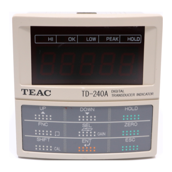
SETTING KEY PAD 1-1-1. Status Display The TD-240A status is indicated. Setting items are indicated when setting. HI: This LED turns on when the indicated value is larger than the set value of the high limit(indicated value > high limit)... -
Page 11: 1-1-2.Numerical Display
1.FUNCTIONAL DESCRIPTIONS 1-1-2. Numerical Display The three types of display are provided. 1)Indicated value 2)Set value 3)Overflow display • Minus overflow of the A/D converter (- LOAD) • Plus overflow of the A/D converter (LOAD) • Indicated value overflowed (indicated value <- 19999) (OFL1)... - Page 12 1.FUNCTIONAL DESCRIPTIONS Validates setting items and set values. Starts the Hold function. To cancel the Hold function, HOLD HOLD press key again. Forcibly resets the indicated value to zero (digital zero function). ZERO When the calibration LOCK is turned off, the digital zero function is not activated using this key.External DZ input is also disabled.
-
Page 13: 1-2.Rear Panel
1.FUNCTIONAL DESCRIPTIONS 1-2. Rear Panel AC INPUT TERMINAL BOARD SIGNAL AC IN INPUT/OUTPUT TERMINAL BOARD OPTION SLOT F.G. SER. No. FRAME GROUND GUARD GROUND MADE IN JAPAN 1-2-1. GUARD GROUND This is a guard ground terminal block. Be sure to ground the guard ground terminal to prevent electric shocks and failures due to static electricity.(The frame and the guard ground terminal are conducted.)... -
Page 14: 1-2-5.Signal Input/Output Terminal Board
SHIELD cable of the sensor. 1・2 : Two-wire serial interface (SI/F) for connecting printers and external display from TEAC. This interface has no polarity and can connect up to three external devices. Use parallel two-core cables or captire cables. 3 ~ 6: Output terminals of the high/low limit relays. - Page 15 1.FUNCTIONAL DESCRIPTIONS 7・8: Terminals for inputting hold signals 7・・・Hold input 8・・・ COM 8・9: Terminals for inputting digital zero signals. Available in LOCK ON only. 9・・・DZ input 8・・・ COM 10・11: Terminal for output of a voltage proportional to the sensor input. Output voltage is approx.
-
Page 16: Connection
2.CONNECTION 2. CONNECTION 2-1. Connecting to Cage Clamp Terminal Block 1.Strip the casing 0.2in (6mm) on the cable to be connected. 0.2in 2.Twist the bare wire to fit the terminal hole. 3.Insert the supplied screwdriver into the upper hole and lift upward. 4.Insert the twisted wires into the lower hole. -
Page 17: 2-2.Connecting Strain Gauge Sensor
2.CONNECTION 2-2. Connecting Strain Gauge Sensor ・4-wire sensor (+ EXC) + IN (- SIG) - OUT + OUT TD-240A (- EXC) - IN (+ SIG) (SHIELD) ・6-wire sensor + IN (+ EXC) (- SIG) - OUT + OUT TD-240A (- EXC)... -
Page 18: 2-3.Connecting Power Input Terminal
F.G. Connect the positive (+) side of the power source to the red screw side of the terminal block on the back of the TD-240A, and its negative (-) side to the black screw side.The input voltage is 12V-24V DC. -
Page 19: 2-4.Connecting Si/F
2-4. Connecting SI/F Two-wire serial interface (SI/F) for connecting printers and external display from TEAC. This interface has no polarity and can connect up to three external devices. Use parallel two-core cables or captire cables. TD-240A 1 SI/F 2 Printer... -
Page 20: 2-5.Connecting High / Low Limit Relays
2.CONNECTION 2-5. Connecting High / Low Limit Relays ・Connecting External Load [ High limit relay ] AC Power Supply Spark Killer TD-240A Varistor Connect a spark killer as near the load as possible. Load [ Low limit relay ] 3... -
Page 21: 2-6. Connecting Hold And Digital Zero Signals
2.CONNECTION 2-6. Connecting Hold and Digital Zero Signals ・Equivalent circuit (input) [ Hold input ] TD-240A Inside Outside → ← Toggleelay switch +12V Relay Contact Ic=Approx.8mA Transistor Push switch * TTL open [ DZ input ] collect output ON when IN is ’H Connect 9 and 8. -
Page 22: 2-7.Connecting Voltage Output (Vol Out)
2.CONNECTION 2-7. Connecting Voltage Output (VOL OUT) Terminal for out put of a voltage proportional to the sensor input . Output voltage is approx. 2V per 1mV/V(sensor input). TD-240A ← Inside Outside → + External device - Load resistance 2kΩor above... -
Page 23: Setting Mode Configuration
3.SETTING MODE CONFIGURATION 3. SETTING MODE CONFIGURATION 3-1. Selection of Setting Items Setting Mode 1 Setting Mode 2 DOWN DOWN High Limit Digital Filter (P.39) (P.31) DOWN DOWN Low Limit (P.31) Analog Filter (P.40) High/LowLlimit Motion Detect (P.33) (P.41) Comparison Mode (time)... - Page 24 3.SETTING MODE CONFIGURATION Setting Mode3 Setting Mode4 DOWN DOWN LOCK BCD Data Update Rate (P.62) (P.49) DOWN DOWN Scale (P.50) Division (P.66) RS-232C Display (P.51) Frequency (P.75) D/A Zero Setting (P.52) Excitation Voltage (P.75) D/A Full Scale Setting...
-
Page 25: 3-2.Display Of Setting Items
3.SETTING MODE CONFIGURATION 3-2. Display of Setting Items Blnking ・Mode1 (1) High Limit PEAK HOLD (2) Low Limit PEAK HOLD (3) High/Low Limit Comparison PEAK HOLD Mode PEAK HOLD (4) Hysteresis PEAK HOLD (5) Digital Offset PEAK HOLD (6) Near Zero ・Mode2 (1) Digital Filter PEAK... -
Page 26: 3-3.List Of Values
3.SETTING MODE CONFIGURATION ・Mode3 (1) LOCK PEAK HOLD (2) Scale Division PEAK HOLD (3) Display Frequency PEAK HOLD (4) Excitation Voltage PEAK HOLD ・Mode4 (1) BCD Data Update Rate PEAK HOLD (2) RS-232C PEAK HOLD (3) D/A Zero Setting PEAK HOLD (4) D/A Full Scale Setting PEAK... - Page 27 3.SETTING MODE CONFIGURATION Setting Mode2 Item Default Set Value Calibration LOCK LOCK Digital Filter ○ Analog Filter ○ Motion Detect(time) ○ Motion Detect(band) ○ Zero Tracking(time) ○ Zero Tracking(band) ○ Hold Mode ○ Automatic Printing ○ Hold Value Printing ○ Setting Mode3 Item Default...
-
Page 28: 3-4.Setting Procedure
3.SETTING MODE CONFIGURATION 3-4. Setting Procedure “F1” of setting Mode1 is displayed. “F2” of setting Mode2 “F3” of setting Mode3 “F4” of setting Mode4 is displayed. is displayed. is displayed. DOWN DOWN DOWN DOWN Select a Select a Select a Select a setting item.. -
Page 29: Calibration
4.CALIBRATION 4. CALIBRATION "Calibration" refers to an operation whereby matching between the TD-240A and a strain gauge sensor is obtained. The TD-240A uses the two calibration methods as described below. ◇ Equivalent Input Calibration This approach uses no actual loads but key entry of the rated output value of the strain gauge sensor (mV/V) and the rating value (value to be displayed). -
Page 30: 4-1.Equivalent Input Calibration Procedure
◇ Actual Load Calibration This approach provides calibration by applying an actual load to the strain gauge sensor and inputting the actual load value. This calibration is without little errors and more correct. TD-240A Actual load Strain gauge sensor Indicated value 4-1. - Page 31 4.CALIBRATION ・Releasing Calibration LOCK Releasing Calibration LOCK 1)Select setting mode 3. 2)Select calibration lock. DOWN Calibration LOCK 1 : ON 0 : OFF DOWN key to set the calibration lock of OFF(0) . then use key to validate the setting. To return to the indicated value display, press key.
- Page 32 4.CALIBRATION ・Setting of Scale Division (Omissible if no change is needed) Setting of Scale Division 1) Select setting mode 3. 2) Set the scale division. DOWN Press twice. Scale Division ( 001 to 100) DOWN keys to set the scale division, then use key to validate the setting.
- Page 33 4.CALIBRATION ・Equivalent Input Calibration Equivalent Input Calibration 1) Start the equivalent input calibration. Example of a sensor having the output value of 2.010mV/V for rated 100.00kgf (N) SHIFT Rated Output Value ( 0.500 to 3.000mV/V) 2) Set the rated output value of the sensor. DOWN keys to set the rated output value,...
- Page 34 4.CALIBRATION ・Calibration LOCK CalibrationLOCK 1) Select setting mode 3. 2) Select calibration lock. DOWN Calibration LOCK 1 : ON 0 : OFF DOWN 3) Use key to set the calibration lock of ON(1) . then use key to validate the setting. To return to the indicated value display, press key.
-
Page 35: 4-2.Actual Load Calibration
4.CALIBRATION 4-2. Actual Load Calibration The actual load calibration uses the following procedure Releasing Calibration LOCK Release the calibration LOCK that inhibits calibration. Set the minimum value of the digital change desired. Setting of Scale Division (omissible if no desired value is present). Zero Calibration Set the zero point of the strain gauge sensor. - Page 36 4.CALIBRATION ・Releasing Calibration LOCK Releasing Calibration LOCK 1) Select setting mode 3. 2) Select calibration lock. DOWN Calibration LOCK 1 : ON 0 : OFF DOWN key to set the calibration lock of OFF(0) . then use key to validate the setting. To return to the indicated value display, press key.
- Page 37 4.CALIBRATION ・Setting of Scale Division(omissible if no change is needed) Setting of Scale Division 1) Select setting mode 3. 2) Set the scale division. DOWN Press twice. Scale Division ( 001to 100) DOWN keys to set the scale division, then use key to validate the setting.
- Page 38 4.CALIBRATION ・Actual Load Calibration Actual Load Calibration 1) Apply an actual load to the sensor and set the actual load value. Indicated Value of(00000 to 19999) Actual Load Value DOWN keys to set the actual load value, then key to validate the setting. To move the decimal point, press key at a blinking digit.
- Page 39 4.CALIBRATION ・Calibration LOCK Calibration LOCK 1) Select setting mode 3. 2) Select calibration lock. DOWN Calibration LOCK 1 : ON 0 : OFF DOWN 3)Use key to set the calibration lock of ON(1) . then use key to validate the setting To return to the indicated value display, press key.
-
Page 40: Setting Of Functions
5.SETTING OF FUNCTIONS 5. SETTING OF FUNCTIONS 5-1. High /Low Limit Value High / Low limit value are functions whereby the high output is turned on when the indicated value exceeds the high / low output is turned on when it drops below the low limit. - Page 41 5.SETTING OF FUNCTIONS Setting of High/Low Limit Value 1) Select setting mode 1. 2) Select high limit value. DOWN High Limit Value ( 00000 to ± 19999) DOWN keys to set the high limit value. SHIFT Press key to place a minus sign. press key to validate the setting.
-
Page 42: 5-2.High / Low Limit Comparator Mode
5.SETTING OF FUNCTIONS 5-2. High / Low Limit Comparator Mode High / Low Limit Comparator Mode 1)Select setting mode 1. 2)Select high / low limit comparator mode. DOWN Press three times. High / Low Limit Comparator Mode Comparison is made at stable 3 :... -
Page 43: 5-3.Hysteresis
5.SETTING OF FUNCTIONS 5-3. Hysteresis The Hysteresis function provides a range of high/low limit comparator off. Usually the high limit comparator is turned on when the indicated value is above the high limit value and turned off when below. If you set a hysteresis range, the comparator is turned off when the indicated value is below the high limit value by the hysteresis setting. - Page 44 5.SETTING OF FUNCTIONS ・Hysteresis operation Indicated value High limit value Hysteresis range Low limit value + - Time High limit relay HI LED Relay OFF Relay OFF Relay ON LED ON LED OFF LED OFF Low limit relay LO LED Relay OFF Relay ON Relay ON...
- Page 45 5.SETTING OF FUNCTIONS Setting of Hysteresis 1) Select setting mode 1. 2) Select hysteresis. DOWN Press four times. Hysteresis (0000 to 9999) DOWN keys to set the hysteresis range, then use key to validate the setting. To return to the indicated value display, press key.
-
Page 46: 5-4.Digital Offset
5.SETTING OF FUNCTIONS 5-4. Digital Offset This function subtracts a set value from the indicated value. If you make digital offset, the value which is obtained by subtracting the set value from the indicated value will be displayed. This is convenient when you cannot obtain zero by unloading the equipment for some reason or when you want to give offset. -
Page 47: 5-5.Near Zero
5.SETTING OF FUNCTIONS 5-5. Near Zero The Near Zero function detects that the indicated value is near zero. Near Zero ON/OFF is closely related to Automatic Printing and High and Low Limit Comparator Mode. For details, see High and Low Limit Comparator Mode on page 33 and Automatic Printing on page 46 . -
Page 48: 5-6.Digital Filter
5.SETTING OF FUNCTIONS 5-6. Digital Filter The Digital Filter function obtains the moving average of Analog-to-Digital(A/D) converted data and stabilizes the indicated values. The moving average count can be selected from 4 to 64. Setting of Digital Filter 1) Select setting mode 2. 2) Select digital filter. -
Page 49: 5-7.Analog Filter
5.SETTING OF FUNCTIONS 5-7. Analog Filter This is a lowpass filter filtering the strain gage sensors input signal and cutout the noise element. Lowpass filter cutout freguency is selectable in the 4/10/100/3k Hz. Setting of Analog Filter 1) Select setting mode 2. 2) Select analog filter. -
Page 50: 5-8.Motion Detect
5.SETTING OF FUNCTIONS 5-8. Motion Detect Setting of parameters for detecting stable measurement is required. If the difference between the current indicated value and that of 100msec before fall within the specified range and the status last for a specified time, indicated values are assumed stable. - Page 51 5.SETTING OF FUNCTIONS Setting of Motion Detect 1) Select setting mode 2. 2 ) Select motion detect(time). DOWN Press three times. Motion Detect(time) (0.0 to 9.9s) DOWN keys to set the motion detect(time) then use key to validate the setting. 3) Select motion detect(range).
-
Page 52: 5-9.Zero Tracking
5.SETTING OF FUNCTIONS 5-9. Zero Tracking The Zero Tracking function automatically tracks and compensates a fine shift of the zero point due to a factor such as a drift. Setting of Zero Tracking 1) Select setting mode 2. 2) Select zero tracking(Time). DOWN Press five times. - Page 53 5.SETTING OF FUNCTIONS ・The Zero Tracking function automatically resets the zero point to zero at a specified time interval when the zero point move amount is below the specified range. ・The time (tracking delay) is set in units of 0.1 seconds, from 0.1 to 9.9 seconds. The range (tracking band)...
-
Page 54: 5-10.Hold Mode
5.SETTING OF FUNCTIONS 5-10. Hold Mode The TD-240A provides the Peak Hold function to hold and display the peak value (maximum value) of the input signal, and the Sample Hold function to hold and display an optional point. Setting of Hold Mode 1) Select setting mode 2. -
Page 55: 5-11.Automatic Printing
5-11. Automatic Printing The Automatic Printing function automatically prints out indicated values on a TEAC printer connected to the TD-240A over the SI/F. Printing is made when indicates vales are stable. (Parameter for stabilization is set in the Motion Detect function.) The stabilized indicated value can be held for three seconds (indicated value hold function)... - Page 56 5.SETTING OF FUNCTIONS Time Near zero Indicated value Stable Near zero 3 seconds Hold ↑ Automatic printing Setting of Automatic Printing 1) Select setting mode 2. 2) Select automatic printing. DOWN Press eight times. Automatic printing 2 : Automatic printing ON, Indicated value HOLD 1 :...
-
Page 57: 5-12.Hold Value Printing
5.SETTING OF FUNCTIONS 5-12. Hold Value Printing The Hold Value Printing function automatically prints out the peak value (held value) on a TEAC printer connected to the TD-240A over the SI/F. Setting of Hold Value Printing 1) Select setting mode 2. -
Page 58: 5-13.Lock
5.SETTING OF FUNCTIONS 5-13. LOCK The Setting value LOCK function inhibits changes to setting to prevent changes to set values or calibrated values through misoperation. Setting of LOCK 1) Select setting mode 3. 2) Select lock. DOWN Select Hold key Setting Value LOCK operation 1 :... -
Page 59: 5-14.Scale Division
5.SETTING OF FUNCTIONS 5-14. Scale Division This function sets the minimum value of the digital change. Setting of Scale Division 1) Select setting mode 3. 2) Select scale division. DOWN Press twice. Scale Division (001 to 100) DOWN key to set the scale division, then use key to validate the setting. -
Page 60: 5-15.Display Frequency
5.SETTING OF FUNCTIONS 5-15. Display Frequency The Display frequency function is used to select the times the indicated values are displayed per second. A/D conversion count is fixed to 100 per second. Setting of Display Count 1) Select setting mode 3. 2) Select display frequency. -
Page 61: 5-16.Excitation Voltage
To return to the indicated value display, press key. CAUTION Use a strain gauge sensor to be connected to the TD-240A whose maximum excitation voltage is above the bridge excitation voltage specified. If the bridge excitation voltage is greater than the maximum excitation... -
Page 62: Hold Function
6HOLD FUNCTION 6 HOLD FUNCTION 6-1. Peak Hold ・Peak Hold Operation Indicated value Sensor input value Peak hold section Peak hold release Time HOLD Key input HOLD LED LED lighting Peak hold start Peak hold reset... - Page 63 6HOLD FUNCTION Indicated value Sensor input value Peak hold section Peak hold release Time Hold input HOLD LED LED lighting reset Peak hold start Peak hold...
- Page 64 6HOLD FUNCTION ・Timing Chart Indicated value Sensor input Time Hold input Display and BCD output t1 : MAX 25mS t2 : MAX 10mS t3 : MAX 25mS t4 : MIN 25mS : Time from the short-circuiting of the hold input (OFF → ON) to the display of the peak hold value.
-
Page 65: 6-2.Sample Hold Operation (Digital Hold)
6HOLD FUNCTION 6-2. Sample Hold Operation (Digital Hold) ・Sample Hold Operation Indicated value Sensor input value Time HOLD Hold section Key input HOLD LED LED lighting Indicated value Sensor input value Time Hold input Hold section HOLD LED LED lighting... - Page 66 6HOLD FUNCTION ・Timing Chart Indicated value Sensor input Time Hold input Display and BCD output t1 : MAX 25mS t2 : MAX 25mS t3 : MAX 25mS t4 : MIN 25mS : Time from the short-circuiting of the hold input (OFF → ON) to the display of the hold value.
-
Page 67: Digital Zero Function
7.DIGITAL ZERO FUNCTION 7. DIGITAL ZERO FUNCTION This function makes the indicated value zero instantly by a key operation. Setting of Digital Zero 1) Perform digital zero. ZERO 2) When the indicated value becomes zero, digital zero is completed. Digital zero will not work when the calibration value LOCK is turned off. -
Page 68: Bcd Data Output(Td
8.BCD DATA OUTPUT(TD-2403) 8. BCD DATA OUTPUT(TD-2403) The BCD Data Output Interface is for transferring indication values in BCD (Binary coded Decimal) from to PC's PLC's or sequences for controlling, processing and recording data. The internal and external circuits are opto-isolated. 8-1. -
Page 69: Logic Switching
When COM and pin 28 are left open, the negative logic is used. When COM and pin 28 are short-circuited, the positive logic is used. 8-3. Equivalent Circuit ・Output The signal output circuit employs the TTL open collector output TD-240A Vext Inside outside Vceo=30V(max) Ic =50mA (max) ●... -
Page 70: Signal Timing
8.BCD DATA OUTPUT(TD-2403) ・Input Open OFF TD-240A Short Inside Outside Transistor Ic=Approx. 6mA Switch TTL open collector output * 注 意 注 意 ・Avoid applying external voltages to the signal input circuit. ・Avoid applying external voltages to the signal input circuit. -
Page 71: Bcd Data Update Rate Selection
8.BCD DATA OUTPUT(TD-2403) ・STROBE BCD data is updated on a per A/D conversion and the strobe pulse synchronous with the BCD data is output.Use the rising edge of the pulse to read data BCD data OVER STROBE strobe range 8-5. BCD Data Update Rate Selection BCD Data Update Rate Selection 1) Select setting mode 4. - Page 72 8.BCD DATA OUTPUT(TD-2403) Normaly,BCD data update synchronous the A/D conversion (100 times/sec). When the BCD input equipment is low ability and can not read out the high rate of 100 times/sec., set the BCD data update rate is low.
-
Page 73: Communication Specifications
9.RS-232C INTERFACE(TD-2404) 9. RS-232C INTERFACE(TD-2404) RS-232C interface is used to read out the indicated value and the state of TD-240A and to write set values into TD-240A. It is convenient to connect TD-240A with a computer, a process controller and a sequencer, etc. to make processing such as control, aggregation, recording and so on. -
Page 74: Connector Pin Assignment
9.RS-232C INTERFACE(TD-2404) 9-1-2. Connector Pin Assignment Adaptable plug :25-pin D-sub connector * * 9-1-3. About Cables PC etc… TD-240A cross cable TxD TxD RxD RxD (CD) (DSR) ※ The avobe diagram is for connecting a personal computer as a DTE(Data Terminal Equipment)device. -
Page 75: Setting Rs-232C Interface
9.RS-232C INTERFACE(TD-2404) 9-2. Setting RS-232C Interface This will set the RS-232C communication conditions of TD-240A. Setting of RS-232C 1) Select setting mode 4. Press three times. 2) Select RS-232C. DOWN Press twice. Stop Bit Communication Mode 1 : 2bit 0 : 1bit Communication Mode 2 2 :... -
Page 76: Communication Mode
9-4. Communication Format 1. Communication Mode 0 ・Reading Out the Indicated Value (the sign, indicated value with 5 digits and decimal point) Host A CR CR LF + TD-240A ・Reading Out the Status (seven digits) Host D CR CR LF TD-240A 1:ON... - Page 77 9.RS-232C INTERFACE(TD-2404) ・Write in of the set value Set value ( High Limit LOCK) CR LF Low Limit Set value ( LOCK) Set value CR LF High/Low Limit ( Comparison Mode LOCK) CR LF Hysteresis Set value ( LOCK) Digital Offset CR LF Set value (...
- Page 78 Do not put other than zero into a place which is set zero. ※ It is impossible to write W 24 and W 34 . ・Reading out Set Values Host W W CR LF TD-240A Set value No. Set value No. The same format as write-in of set values.
- Page 79 9.RS-232C INTERFACE(TD-2404) ・Command (host → TD-240A) Hold C E Hold Reset C F (This is effective only when the calibration Digital Zero C G value LOCK is "1.") (This is effective only when the calibration Digital Zero Reset C H...
- Page 80 9.RS-232C INTERFACE(TD-2404) * 1 O..Over Load(LOAD,OFL) S ..Stable M..Not Stable H..Hold * 1 Priority H > O >(S or M) * 2 A..Zero Tracking OFF T ..Zero Tracking ON * 3 H..High Limit ON L ..Low Limit ON G..High / Low Limit OFF N..High / Low Limit ON F ..Compare OFF...
- Page 81 10. D/A CONVERTER(TD-2407) This is a converter to obtain an analog output which is linked with the indicated values of TD-240A. The range of the analog output is from 0 to +10V for the voltage output or from 4 to 20mA for the constant current output.
-
Page 82: Obtaining Voltage Output Signal
10.D/A CONVERTER(TD-2407) 10-1. Obtaining Voltage Output Signal Use + and - terminals of TD-240A connecting to them an external equipment (with load resistance of 2KΩ or more). TD-240A ← Inside Outside → + + External equipment - - Load resistance: 2KΩ or more 10-2. -
Page 83: About Resolution
10.D/A CONVERTER(TD-2407) 10-3. About Resolution The D/A converter has the resolution of 1/3000 for 0 to 10V (4 to 20mA). CAUTION ・The D/A converter is an option. ・Do not apply voltage externally. If you do, it will break down. ・Do not short-circuit the voltage output. Short-circuiting may cause failure. -
Page 84: Setting D/A Zero Full Scale
10.D/A CONVERTER(TD-2407) 10-4. Setting D/A Zero Full Scale This will set the D/A zero full scale of TD-240A. Setting D/A Zero Full Scale 1)Select setting mode 4. Press three times. 2)Set D/A zero. DOWN Press three times. D/A Zero Value (00000 to ± 19999) -
Page 85: About D/A Output Error
10.D/A CONVERTER(TD-2407) 10-5. About D/A Output Error This is an error which is output only when D/A option is provided. D/A output is less than the range of output. For current output: 4mA - 25% or less (about 0mA or less) For voltage output: 0V - 25% or less (about -2.5V or less) The D/A output exceeds the range of the output. -
Page 86: Dc Power Source
Connect the positive (+) side of the power source to the red screw side of the terminal block on the back of the TD-240A, and its negative (-) side to the black screw side. Input voltage range ( voltage between terminals of the F340A) DC12 ~... -
Page 87: Overscale/Error Displays
12.OVERSCALE/ERROR DISPLAYS 12. OVERSCALE/ERROR DISPLAYS 12-1. Overscale Display Minus overflow of the A/D converter (under -3.2mV/V between ± SIG) Plus overflow of the A/D converter (over 3.2mV/V between ± SIG) Indicated value overflowed (indicated value<-1999) Indicated value overflowed (indicated value>1999) 12-2. -
Page 88: Self-Check Function And Initialization
1)Turn off the power to the TD-240A. 2)Turn on the power with key held down. The self-check is completed in 30 seconds. The display " " should appear, then the indicate value should follow.This ensures that the TD-240A is in normal operation. - Page 89 13.SELF-CHECK FUNCTION AND INITIALIZATION Self-check (Visual-Check Sequence)...
-
Page 90: Initialization
(obtained through zero calibration and span calibration) to the factory setting Setting Method 1)Turn off the power to the TD-240A. 2)Turn on the power with keys held down. The initialization follows the self-check. - Page 91 13.SELF-CHECK FUNCTION AND INITIALIZATION Initialization Sequence...
-
Page 92: Td-240A Block Diagram
13.SELF-CHECK FUNCTION AND INITIALIZATION 13-3. TD-240A Block Diagram... -
Page 93: Dimensions
14.DIMENSIONS 14. DIMENSIONS PEAK HOLD OPTION OPTION SI/F SI/F HOLD HOLD F340A DIGITAL DIGITAL TD-240A INDICATOR TRANSDUCER INDICATOR 2.5V VOL OUT VOL OUT DOWN HOLD +EXC +EXC F340A DIGITAL -SIG INDICATOR -SIG 2.5V 100 - 240V ~ -EXC -EXC ZERO... -
Page 94: Specifications
15.SPECIFICATIONS 15. SPECIFICATIONS 15-1. Analog Section Bride Voltage DC 10V ± 10% DC 2.5V ± 10% Output current of max 30mA Changable by setting key Pad Signal input range - 3.0 to 3.0mV/V Equivalent input calibration range 0.5 ~ 3.0mV/V Equivalent input calibration error <... -
Page 95: Indicator Section
15.SPECIFICATIONS 15-2. Indicator Section Indicator Numeric display (5 digits), 15mm in height, red LED Numeric 5digits ± Indicatid value - 19999 to 19999 Decimal point Selectable Items Status HI,OK,LOW,PEAK,HOLD Red LED 5 Count 3,6,13,25times/sec. Selectable 15-3. Setting Section Items Calibration:Zero/Span calibration (actual load calibration, equivalent input calibration)... -
Page 96: Option
15.SPECIFICATIONS 15-6. Option ・TD-2403 BCD Parallel data output ・TD-2404 RS-232C Interface ・TD-2407 D/A Converter 15-7. General Specifications Power voltage 100V to 240V AC ( + 10% - 15%) - AC spec: [Free power supply 50Hz/60Hz] - DC spec: 12V to 24V DC ( ± 15%) (Depending on the request at the time of order) Power consumption - AC spec: 15W max. -
Page 97: Accessories
・3P - 2P conversion adapter ....1 ・BCD Output connector ..... 1(when BCD option is supplied) ・TD-240A operational manual... -
Page 98: Conformity To Ec Directives
EN61000-4-11,EN61000-3-2,EN61000-3-3 When installing, attention should be given to the following. 1. Since the TD-240A is defined as an open type (built-in equipment), be sure to install the TD-240A and fix to a panel or the like for use. 2. Use the attached power cable. - Page 99 Connection of Lightning serge protect The F340A main body conforms to EMC directive EN61000-4-5 (lightning surge immunity) in combination with the lightning surge protect. ● AC Spec. TD-240A Lightning surge protect The cable of the EU outlet shape is required for connection MAINTRAB MNT-1D of lighting serge protect.
- Page 100 TEAC INSTRUMENTS CORPORATION 83 IMAIKAMIMACHI, NAKAHARA-KU, KAWASAKI JAPAN Phone:(044)-711-5221 Fax: (044)-711-5240...
Need help?
Do you have a question about the TD-240A and is the answer not in the manual?
Questions and answers