Teac TD-9000T Instructions For Use Manual
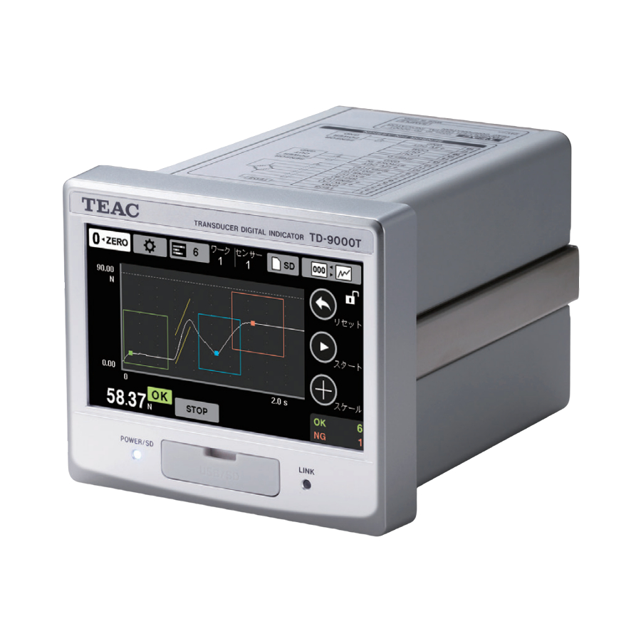
Transducer digital indicator
Hide thumbs
Also See for TD-9000T:
- Instructions for use manual (28 pages) ,
- Instructions for use manual (20 pages)
Table of Contents
Advertisement
Quick Links
Advertisement
Chapters
Table of Contents

Related Manuals for Teac TD-9000T


Summary of Contents for Teac TD-9000T
- Page 1 D01353105D Transducer Digital Indicator Instructions for Use TD-9000T...
-
Page 2: Introduction
Linearization function improves linearity of load measurements. SDHC Logo is a trademark of SD-3C, LLC. TEAC is a trademark of TEAC CORPORATION, registered in the U.S. and other countries. Other company names, product names and logos in this document are the trademarks or registered trademarks of their respective owners. -
Page 3: Using Sd Cards
Do not use a computer to delete, move or otherwise alter data recorded on an SD card. Doing so could cause the TD-9000T to become unable to properly record data. Write-protection switch Writing data can be prohibited by moving Insertion and removal the switch to the LOCK position. -
Page 4: Safety Information
Safety information This document describes the safety instructions for the operation of the digital indicator. Before operating the product, read this doc- ument carefully to familiarize yourself with the unit. Follow the instructions below to avoid risk of WARNING serious personal injury and death. Never use beyond the rated specifications as there is the danger of property damage, injury, fire or electrical shock. - Page 5 Safety information Follow the instructions below to avoid risk of CAUTION personal injury or property damage. Disconnect the power cord when performing the following. When wiring or connecting cables to the terminal banks for connecting the DC power supply, load cells and external inputs and outputs Connecting the ground line Wait for at least one minute between turning the unit on and off.
- Page 6 Safety information Model for USA Model for Europe Supplier’s Declaration of Conformity DECLARATION OF CONFORMITY Model number: TD-9000T This product complies with the Trade name: TEAC European Directives request, and the Responsible party: TEAC AMERICA,INC. other Commission Regulations. Address: 10410 Pioneer Blvd. Unit #1, Santa Fe Springs, DECLARACIÓN DE CONFORMIDAD...
- Page 7 In no event shall TEAC be liable for any damages local, regional and national governments. whatsoever (including, without limitation, damages for loss of...
-
Page 8: Table Of Contents
Contents Introduction ..........2 4-1-3. - Page 9 Contents 6-1-4. Unique communication protocols ....79 7. Setting lists ..........87 7-1.
-
Page 10: Names And Functions Of Parts
1. Names and functions of parts 1-1. Front POWER/SD indicator This lights blue when the unit is on. It lights magenta when an SD card is being accessed. Recording media slot cover Open the cover to reveal the USB port (left) and SD card slot (right) inside. -
Page 11: Back
1. Names and functions of parts 1-2. Back SENSOR connector Insert the included sensor connector plug here. CONTROL connector DC power supply input terminals Connect a DC power supply. The voltage range is DC 24 V ±10%. FG (frame grounding) terminal Frame grounding terminal for DC power supply. -
Page 12: Home Screen
1. Names and functions of parts 1-3. Home Screen Reset button This clears hold display. When the unit is turned on, the screen last open when it was Load unit turned off reopens (indicator value or waveform screen). The load unit shown is set by the Unit shown item on 1-3-1. -
Page 13: Waveform Display
1. Names and functions of parts Load indicator value Waveform This shows the current indicator value. This can also This shows the measurement results as a waveform. show the zone judgment hold value after measurement Values between the low limit and the high limit are shown (page 57). -
Page 14: Zooming The Waveform Display In/Out
1. Names and functions of parts 1-3-3. Zooming the waveform display 1-4. Buttons and their functions in/out Button Function On the waveform display screen, touch the ¥ button to open the GRAPH SCALE CHANGE SCREEN. Digital zero (page 15). o This only increases/decreases the scale of the load waveform. Open SETTINGS screen (page 27). -
Page 15: Digital Zero
1. Names and functions of parts 1-4-1. Digital Zero Touch to return to the previous screen. The current indicator value for load or displacement becomes zero. Touch the ZERO button on the screen to show options for Show the waveform of the selected position. the sensor to execute digital zero, and select the desired one −, + (page 31). - Page 16 1. Names and functions of parts 1-4-2-3. Operation during waveform display 1-4-2-4. Saved data overview Rather than saving all sampled data as is, this unit saves data Showing multi-zone judgment hold positions at intervals. Touch the 5 button to show the cursor at the zone hold posi- 2240 data points will be saved in the X axis full scale range.
-
Page 17: Sensor Memory/Work Number Setting
1. Names and functions of parts 1-4-4. SD button The previous waveforms are shown using the interval data. If a hold position is not at an interval data point, the hold Touch the SD button to open the following screen. position data will be shown in place of the sample data imme- diately preceding it. -
Page 18: Status Change Illustration
1. Names and functions of parts 1-5. Status change illustration Power supply ON CONTINUE (continuous judgment mode) WAIT TRG* (waiting to start measurement) REC (measuring) STOP (measuring stopped (holding)) Start/stop measurement ON Clear results ON or touch START button or touch Reset button *Will skip if no trigger is set. -
Page 19: Installation
2. Installation Follow these procedures to install the TD-9000T in a control From the back, attach the guide rails removed in panel. step 2 and secure them using screws in two places. (Recommended tightening torque: 0.5 N·m ≈ 5.1 kgf·cm) Open a hole in the panel in accordance with this... -
Page 20: Making Connections
3. Making connections 3-1. Connecting to the SENSOR 3-2. Connecting a strain gauge connector transducer A 2-piece type connector is used. Insert the included sensor connector plug into the SENSOR 3-2-1. About the remote sensing connector. function When wiring the sensor connector plug, press the button for each pin while inserting the wire. -
Page 21: Displacement Sensor
3. Making connections Connecting TEDS sensors and 4-wire sensors The wire colors are those that we use in the strain gauge trans- ducers that we make. Strain gauge transducer TD-9000T Terminal TEDS Signal Wire color Teds Data number Memory TEDS... -
Page 22: Displacement Sensor (Pulse)
SHIELD 3-3-2. Displacement sensor (pulse) counting method Down count The TD-9000T has modes that support A phase only and AB phase (2-phase) output signals from displacement sensors (pulse). The count value changes as shown below for A phase only and Counts occur at both the rising and falling edges of A and B AB phase output. -
Page 23: D/A Converter
Load cell error D/A output setting of the sensor screen (page 29). Measurement complete Trigger output 2 Trigger output 1 TD-9000T Band judgment output (load HI) Band judgment output (load OK) Band judgment output (load LO) Judgment output (displacement HI) Judgment output (displacement OK) -
Page 24: Control Output Signals
3. Making connections 3-5-2. Control output signals 3-6. Control signal input terminals (CONTROL connector) Unit error This becomes ON if the load cell input exceeds the ±3.2mV/V range. Terminal Signal number Load cell error COM signal This becomes ON if the load cell input exceeds the maxi- COM signal mum display value. -
Page 25: Connecting Control Input Terminals
Shorts occur from both contact and non-contact (transistor, Enable the backlight while this is ON. TTL open collector). Prevent touchscreen operation TD-9000T Disable touchscreen operation while this is ON. Force reset Setting this to ON restarts the unit. Switch work... -
Page 26: Rs-232C Connector
3. Making connections Start/stop measurement 3-8. Connecting the DC power When “MEASURE. START. COND. ” or “MEASURE. STOP. COND. ” is set to “EXT. SIGNAL” on the WORK settings screen, this supply input terminals controls starting and stopping measurement. Select the control method with EXT. START/STOP (page 67). The DC power supply input voltage should be 24 V ±10%. -
Page 27: Settings
4. Settings Use CALIB. & SYSTEM to make calibration and system settings. 4-1. Basic operation WORK opens work settings. Display example ⚙ Touch the button on the HOME Screen to show the SETTINGS screen. Touch buttons with white rectangular borders to execute the action shown on them. -
Page 28: Option Display
4. Settings 4-1-2-1. Inputting numerical setting values 4-1-4. Returning to the Home Screen Touch a number button with a finger, for example, to input Touch the HOME button at the top right of the window to numerical values. return to the Home Screen. Touch OK to set the input value. -
Page 29: Sensor Settings
4. Settings Settings in menus that require warnings are shown when, for ATTENTION example, other settings must also be changed. Changing the sensor memory could change the decimal Information point positions of the parameters saved in the works Display example depending on the calibration values. -
Page 30: D/A Converter
4. Settings 4-2-1. D/A converter Setting example 3 D/A Zero 020.00 The D/A converter allows for analog output that corresponds to the unit indicator value. D/A full scale −100.00 The D/A output circuit is isolated from the main unit circuit. Indicator value D/A output The analog output range is either 0–±10V voltage output or... -
Page 31: Load Cell Calibration
4. Settings Sensor check before calibrating 4-3. Load cell calibration After connecting a sensor and providing power, calibration is not possible if the indicator value is unstable or an error Connecting the unit with a strain gauge transducer and appears. If this occurs, enable static strain display and check setting how the indicator values will be shown is called “cali- the indicator value. -
Page 32: Procedures Shared By All Calibration Methods
4. Settings Procedures shared by all calibration Locking and unlocking calibration values methods Usually, the unit is used with CALIBRATION LOCK set to ON. This must be set to OFF before calibration. After calibration, set it The three calibration methods are equivalent input calibra- to ON again. -
Page 33: Equivalent Input Calibration
4. Settings Remote sensing 4-3-1-1. BRIDGE VOLTAGE Select the bridge voltage to supply to the strain gauge Before connecting a sensor, check its specifications and set transducer. remote sensing on the LOAD CELL screen. o As a reference for setting the bridge voltage, consider that Set to “USED (6 wire)”... - Page 34 4. Settings 4-3-1-6. LINEARIZE CALIB. Confirm the input value. Then, touch ESC to return The linearity of load measurements is improved by increasing to the previous screen. the calibration points. After equivalent input calibration, input the linearization Repeat steps 2–4 to input necessary calibration calibration.
-
Page 35: Actual Load Calibration
4. Settings 4-3-2. Actual Load Calibration 4-3-2-2. ZERO BALANCING With no load on the sensor, touch the CALIBRATION button. Calibrate by applying an actual load to the sensor. o If a calibration error appears, conduct countermeasures according to the error message, and redo calibration. Bridge voltage 4-3-2-3. - Page 36 4. Settings 4-3-2-5. LINEARIZE CALIB. Confirm the input value. Then, touch ESC to return The linearity of load measurements is improved by increasing to the previous screen. the calibration points. Do this after actual load calibration. Repeat steps 2–4 to input necessary calibration values, and touch the OK button.
-
Page 37: Teds Calibration
4. Settings 4-3-3. TEDS calibration 4-3-3-1. TEDS By connecting a sensor that supports IEEE1451.4 Transducer A TEDS sensor has calibration information, including rated out- Electronic Data Sheets (TEDS) to the unit, the rated output put and rated capacity, stored in its memory. stored in the sensor can be loaded and this can be applied to TEDS calibration reads this calibration information to automati- calibration of the indicator with this function. - Page 38 4. Settings 4-3-3-2. TEDS loading 4-3-3-3. ZERO BALANING After loading the TEDS data, the rated output/rated capacity With no load on the sensor, touch the EXECUTE button. is shown. o If a calibration error appears, conduct countermeasures Rated capacity digit shown during TEDS calibration according to the error message, and redo calibration.
- Page 39 4. Settings 4-3-3-6. REWRITE TEDS DATA 4-3-3-7. RESTORE TEDS DATA The current calibration values (rated output and rated capac- Use this to restore the factory default calibration value of a sen- ity) and calibration date will be written to the TEDS memory. sor to which data was written using the REWRITE TEDS DATA The indicator unit will not be written.
-
Page 40: Load Cell Operation Settings
4. Settings 4-3-4. Load cell operation settings LOW-PASS FILTER Set the low pass filter cutoff frequency (Hz). To open the LOAD CELL screen, touch the buttons in the fol- lowing order on the Home Screen. ⚙ CALIB. & SYSTEM SENSOR LOAD CELL NOTE When set to “OFF”, only the AD converter anti-aliasing... -
Page 41: Displacement Sensor Calibration
4. Settings D/Z LIMIT SETTING 4-4. Displacement sensor Set the range for Digital Zero capture. (The setting value unit is the same as for the indicator value.) calibration ATTENTION To open the DISPLACE. SENSOR screen, touch the buttons in If the current sensor input value exceeds the D/Z LIMIT the following order on the Home Screen. -
Page 42: Procedures Shared By All Calibration Methods
4. Settings Procedures shared by all calibration 4-4-1. Equivalent input calibration methods The three calibration methods are equivalent input calibration, actual load calibration and TEDS calibration. All the calibration methods have the same procedures before and after calibration. An overview of the calibration procedures is shown below. Unlock calibration values Calibration Equivalent input calibration or actual load calibration... -
Page 43: Actual Load Calibration
4. Settings Zero balancing DISPLAY VALUE Set this according to the specifications of the sensor. Move the displacement sensor to the reference position, and Calculate the resolution using the following formula. touch the Zero balancing button. The current position of the Resolution = Display value/Count number displacement sensor is saved as the zero point. -
Page 44: Work Settings
4. Settings 4-4-2-2. Voltage output 4-5. Work settings After installing this unit, set the following items when using it the first time. See “4. Settings” on page 27 for information about settings. o Clock settings (page 67) o Connected sensor settings (page 29) o SD card settings (when saving data to an SD card) (page 68) NOTE See “5-3-5. -
Page 45: Continuous Judgment
4. Settings 4-5-1. CONTINUOUS JUDGMENT MEASURE. START. Set the measurement starting method (page 54). Measurement values are compared to comparison values to COND. conduct judgment. Select the signal used for the trigger. Continuous judgment is conducted when “CONTINUE” is the LEVEL status displayed on the screen. -
Page 46: Band Judgment
4. Settings 4-5-2. BAND JUDGMENT SELECT REF. WAVE Measurement waveforms are compared to comparison wave- Set the waveform to use for reference. forms to conduct judgment. Instead of high limit, low limit and other fixed values for continuous judgment, any curved line can be used for comparison. - Page 47 4. Settings WAVE SAMPLING Editing comparison waveforms Touch the WAVE SAMPLING button and then touch the OK Touch the beginning position of the comparison button. If a comparison waveform has been saved in the current waveform to show the cursor, and touch the g work, it will be shown.
-
Page 48: Zone Judgment
4. Settings Loading waveforms When the waveform display horizontal axis is time Set load management values, and conduct judgments. Touch the WAVE LOADING button, and touch the OK button. A list of measurements will be shown. Use the 5 and b Load buttons to select the data, and touch the ENT button to load Load manage-... - Page 49 4. Settings 4-5-3-2. Setting examples JUDGE. METHOD (judgment method) For details about each setting item, refer to the following Select PEAK. explanations. ZONE RANGE Peak hold Select 0.700–1.400 s. This explanation uses settings for conducting peak holds with NOTE multi-zone judgment as an example. (A displacement sensor is After starting measurement, peak holds will be con- not used in this example.) ducted for 0.700–1.400 seconds.
- Page 50 4. Settings Multi-zone judgment (3 points) LOAD HIGH (HI)/LOW (LO) This explanation uses settings for conducting peak, bottom Select 25.00–5.00 N. and inflection point holds with multi-zone judgment as an example. (A displacement sensor is not used in this example.) NOTE Touch the buttons in the following order on the Home Screen Set the range for OK judgment.
- Page 51 4. Settings For inflection points, further settings must be made to conduct Load indicator value inflection point holds. After selecting INFLECTION for the judg- ment method, touch the selection button again to open the NOTE settings screen. See “4-6-4-2-8-1. Setting items” on page 64 for information o These settings will show the peak value of zone 1.
-
Page 52: Band + Zone Judgment
4. Settings 4-5-4. Band + Zone judgment Touch the HOME button to return to the Home Screen, and touch the buttons in the following order to open the settings screen. 4-5-4-1. Setting examples ⚙ WORK ZONE JUDGMENT This explanation uses settings for conducting band judgment and multi-zone judgment (with peak and inflection point Peak hold holds) as an example. -
Page 53: Current Band Wave & Multi-Zone
4. Settings 4-5-5. CURRENT BAND WAVE & MULTI- Displaying and moving bands and spe- ZONE ARRANGEMENT screen cific zones Touch the button of an item to be shown or moved to show Touch the waveform display area on the waveform display only the range of that item screen to open the CURRENT BAND WAVE &... -
Page 54: Start/Stop Measurement
4. Settings EXT. & DISP. 4-6. Start/stop measurement In the same manner as with “EXT. & LOAD” above, after an external signal start condition is realized, measurement will In the following explanation, operation is for when EXT. START/ start when the displacement exceeds the start level (AND STOP has been set to “EDGE”... -
Page 55: Continuous Judgment Timing Chart
4. Settings drawn according to the indicator values. After measurement using another judgment, setting the Clear If the measurement start condition is “EXT. & DISP. ” , indicator results signal to ON will start continuous judgment. values will be saved without resetting. 4-6-3. -
Page 56: Zone Judgment Timing Chart
4. Settings 4-6-4. Zone judgment timing chart 4-6-4-1. Setting items Touch the buttons in the following order on the Home Screen. Switch zone ⚙ WORK ZONE JUDGMENT This is enabled when the “ZONE SWITCHING” setting on the ZONE JUDGMENT screen is set to “EXT. INPUT” (page 57). The zone section is determined by signal ON and OFF. - Page 57 4. Settings LOAD HIGH (HI)/LOW (LO) Set the Y axis management values in the zone. DISPLACEMENT HIGH (HI)/(LO) For X axis displacement, set the displacement manage- ment values in the zone. ATTENTION For details about the method for judging displacement, see “4-6-4-2.
- Page 58 4. Settings 4-6-4-2. Judgment method 4-6-4-2-1. Constant comparison When a measurement value is within a zone, it is compared to Select the hold method used when measurement data is in the high and low limits and judged. the zone. HI: high limit value < measurement value LO: measurement value <...
- Page 59 4. Settings 4-6-4-2-3. Peak The load peak is held when measurement values are in the zone. Hold point Load Internal hold value Measurement value Zone interval Time or displacement Judgment output (load/displacement) Judgment output (load/displacement) If the hold point meets a HI or LO condition, this becomes ON. If the hold point is within the management value range, judgment for this zone will be OK.
- Page 60 4. Settings 4-6-4-2-5. Peak to peak With the point when the zone was entered as zero, the maximum difference between the maximum (peak) and maximum nega- tive-direction (bottom) values for load becomes the hold value when measurement values are in the zone. Hold point Load Hold value...
- Page 61 4. Settings 4-6-4-2-7. Maximum/minimum The maximum and minimum load values are detected when measurement values are in the zone. At the moment that the load difference × scaling factor occurs the number of times set for the detection count, the points when the maximum and minimum values occurred will become the hold points.
- Page 62 4. Settings 4-6-4-2-7-1. Setting items Detecting the maximum/minimum After the maximum or minimum value is detected, at the time when the load value exceeds the load difference × the scaling factor, the A point is held if it is a maximum value hold or the B point is held if it is a minimum value hold.
- Page 63 4. Settings 4-6-4-2-8. Inflection point When measurement values are in the zone, change in the slope of the load value is identified and held. Load Inflection point Time or displacement Zone interval Judgment output Judgment output (load/displacement) If the inflection point meets the conditions for HI or LO, this becomes ON. If the inflection point is within the management value range, judgment for this zone will be OK.
- Page 64 4. Settings 4-6-4-2-8-1. Setting items Inflection point detection C’ When measurement values are in the X axis of the zone, change in the slope of the load value is identified and held. Detection starting STARTING LOAD load value Set the starting load value for inflection point holds. After measurement starts, inflection point hold will start when With the changed load of WIDTH A as C and the changed load the load exceeds the STARTING LOAD.
-
Page 65: System Settings
5. System settings displacement sensors is not possible. 5-1. Lock and language settings o Values for locked settings appear green in the menu and cannot be changed. ⚙ Touch the button on the HOME Screen to show the o ALL LOCK prevents opening any SETTINGS menu other SETTINGS screen. -
Page 66: Memory And Counter Settings
5. System settings OVERWRITING 5-2. Memory and counter settings ALLOW: overwrite the oldest data when the internal memory becomes full To open the SYSTEM screen, touch the buttons in the following FORBID: do not overwrite any data order on the Home Screen. DELETE ALL ⚙... -
Page 67: Various Settings
5. System settings TRIGGER OUTPUT 5-3. Various settings Threshold can be set as desired for load, displacement or OK/NG count value, and triggers can be output to Trigger To open the SYSTEM screen, touch the buttons in the following outputs 1 and 2 (page 68). order on the Home Screen. -
Page 68: Trigger Output
5. System settings 5-3-2. TRIGGER OUTPUT without saving recording data. FORMAT Use to format the SD card. EXPORT THE SETTINGS Setting values can be saved to SD cards. o A file with the name “td9kt_settings.csv” will be saved in the root folder. If a file with the same name already exists, that file will be renamed “td9kt_settings.bak”... - Page 69 5. System settings Recording data example [Information] Device ID,0 device number Date,2020/03/31 measurement date Time,17:47:39 measurement time Sensor No.,4 sensor number Work No.,7 work number Judgment method Sampling Freq.,25kHz sampling frequency Constant (constant judgment) X Axis,Time(sec) X axis Sample Y Axis,Load(N) Y axis Peak X Fullscale,4.00(sec)
-
Page 70: Serial Comm
5. System settings 5-3-4. SERIAL COMM. in load cell cables. Connectors might not be connected properly and wiring might also be incorrect. EXT. TERMINAL CHECK Input terminal Depending on the input signal, LOW (ON with yellow indicator) or HIGH (OFF) is shown. Output terminal Output can be turned ON/OFF for the connectors as desired. -
Page 71: Communication Functions
Set according to the transmission requirements of con- nected equipment. TD FORMAT PARITY BIT This transmission protocol is unique to the TD-9000T. Set according to the transmission requirements of con- nected equipment. TD FORMAT (BCC) This transmission protocol adds checksum (BCC) to the TD STOP BIT FORMAT. -
Page 72: Command Lists
6. Communication functions 6-1-2. Command lists 6-1-2-1. Execution Content Command No. Setting item Note Digital Zero 0000 Clear Digital Zero 0000 Switch to indicator value screen 0000 Switch to static strain screen 0000 Switch to graph screen 0000 Start measurement 0000 Stop measurement 0000... - Page 73 6. Communication functions 6-1-2-5. System Content Command No. Setting item Device number 5500 0–9999 Beep 5501 0: OFF, 1: KEY, 2: KEY + JUDGE External measurement signal mode (EXT. START/STOP) 5502 0: Edge, 1: Level Format 5503 0: YYYY-MM-DD, 1: DD-MM-YYYY, 2: MM-DD-YYYY Date &...
- Page 74 6. Communication functions 6-1-2-6. Calibration 6-1-2-6-1. Sensor Content Command No. Setting item Sensor memory 1000 0: Sensor Memory 1, 1: Sensor Memory 2, 2: Sensor Memory 3, 3: Sensor Memory 4 Sampling rate 1006 0.5 kHz, 1.25 kHz Y axis 1007 0: Load, 1: Load and displacement X axis 1008 0: Time, 1: Displacement...
- Page 75 6. Communication functions 6-1-2-6-4. Pulse displacement sensor Content Command No. Setting item Higher 2 digits (1–15000000) Count number (higher 2 digits) 1600 o Set the higher digits followed by the lower digits. Count number (lower 6 digits) 1601 Lower 6 digits (1–15000000) Display value (equivalent input) 1602 00001–99999...
- Page 76 6. Communication functions 6-1-2-7. Work Content Command No. Setting item Work number 7000 1–16 (enabled only during manual selection) Switch work (WORK SWITCHING) 7001 0: Manually, 1: External input (EXT. INPUT) Copy work 7002 0: All, 1–16: Work number Measurement starting condition 7003 0: EXT.
-
Page 77: Communication Protocol
6. Communication functions 6-1-3. Communication protocol The final characters of commands and responses must be “CR+LF” or “CR”. The final characters are set by the delimiter on the SERIAL COMM. screen (page 71). TD Format does not use checksums. TD Format (BCC) adds checksums after data. NOTE o Since commands 0005, 0006, 0007, 0008, 0010, 0100, 0101, 0110, 0111 and 0112 have unique protocols, they will be described later. - Page 78 6. Communication functions 6-1-3-2. Responses The characters at the beginning of the response show the command execution result. The reply is "ACK" if it was completed properly or "NAK" if it ended in an error. Command execution result when completed properly TD Format HEX 0×06 0×30 0×30 0×37 0×30 0×30 0×30 0×0D 0×0A ASCII ACK...
-
Page 79: Unique Communication Protocols
6. Communication functions 6-1-4. Unique communication protocols This is an explanation of commands for communicating unique protocols. In this section, examples of transmission using TD Format (BCC) are given. To transmit using TD Format, remove the checksum from the transmission examples. Example responses are only given for command execution results that have completed properly. - Page 80 6. Communication functions Data Load value 10: ± sign, 11–16: Load value (including decimal places) Byte ASCII ± × × × × × × Displacement value 18: ± sign, 19–24: Displacement value (including decimal places) Byte ASCII ± × × ×...
- Page 81 6. Communication functions 6-1-4-3. Measurement result polling (0007) If the measurement status of the unit is “Stop”, the status and current judgment result will be returned. If the measurement status of the unit is anything else, only the status will be returned. Command HEX 0×23 0×30 0×30 0×30 0×30 0×30 0×37 0×32 0×37 0×0D 0×0A ASCII...
- Page 82 6. Communication functions 6-1-4-4. Peak & bottom polling (0008) If the measurement status of the unit is “Continue”, the status, peak value and bottom value will be returned. If the measurement sta- tus of the unit is anything else, only the status will be returned. NOTE This command returns the peak and bottom values of continuous judgment.
- Page 83 6. Communication functions 6-1-4-5. Read hold value (0010) If the measurement status of the unit is “Stop”, the status and hold value will be returned. If the measurement status of the unit is any- thing else, an error (NAK) will be returned. Command HEX 0×23 0×30 0×30 0×30 0×30 0×31 0×30 0×30 0×30 0×0D 0×0A...
- Page 84 6. Communication functions 6-1-4-6. Load number of measurement waveform samples (0100) If the measurement status of the unit is “Stop”, the most recent measurement result will be returned. If the measurement status of the unit is anything else, an error (NAK) will be returned. Command HEX 0×23 0×30 0×30 0×30 0×31 0×30 0×30 0×32 0×31 0×0D 0×0A ASCII...
- Page 85 6. Communication functions 6-1-4-7. Load measurement waveform (0101) If the measurement status of the unit is “Stop”, the most recent measurement result will be returned. If the measurement status of the unit is anything else, an error (NAK) will be returned. Command HEX 0×23 0×30 0×30 0×30 0×31 0×30 0×31 0×2c...
- Page 86 6. Communication functions 6-1-4-8. TEDS command format Command numbers 6001–6006 are transmitted in this format. Data is fixed to 8 characters. If the data lacks 8 characters, each opening will be filled with a "0". Command Example of TEDS maximum rated capacity (6002) HEX 0×23 0×30 0×31 0×36 0×30 0×30 0×32 0×32 0×39 0×0D 0×0A ASCII ID number...
-
Page 87: Setting Lists
7. Setting lists 7-1-2. SENSOR 7-1. Setting menu list SENSOR (page 29) SENSOR MEMORY SETTINGS (page 65) SAMPLING RATE LOCK STATUS (page 65) Y AXIS LANGUAGE X AXIS CALIB. & SYSTEM (page 66) X AXIS FULL SCALE INTERNAL MEMORY D/A OUTPUT SETTING OK/NG COUNTERS D/A MAX. -
Page 88: Work
7. Setting lists 7-1-2-2. DISPLACE. SENSOR 7-1-3. WORK DISPLACE. SENSOR (page 41) WORK (page 44) UNIT SHOWN WORK NUMBER CALIBRATION LOCK WORK SWITCHING INPUT MODE COPY WORK (page 45) SENSOR INPUT LOGIC MEASURE. START. PULSE INPUT COND. EQUIVALENT CALIB. (page 42) LEVEL OUTPUT PHASE (AB, A) MEASURE. -
Page 89: Setting Value List
7. Setting lists 7-2. Setting value list 7-2-1. SETTINGS Item Setting Format Default value Setting range/options CALIBRATION LOCK Selection UNLOCK UNLOCK, LOCK WORK LOCK Selection UNLOCK UNLOCK, LOCK LOCK STATUS ALL LOCK Selection UNLOCK UNLOCK, LOCK, PASSWORD LOCK LANGUAGE Selection Japanese Japanese, English, Chinese, Korean 7-2-2. -
Page 90: Sensor
7. Setting lists 7-2-4. SENSOR Item Setting Format Default value Setting range/options SENSOR MEMORY Selection 1–4 SAMPLING RATE Selection 25 kHz 5 kHz, 25 kHz Y AXIS Selection LOAD LOAD, LOAD & DISPLACE. X AXIS Selection TIME TIME, DISPLACE. Time: 80 ms*,170 ms*,400 ms, 800 ms, 2.0 s, 4.0 s, 10.0 s, 30.0 s, 60.0 s, 90.0 s X AXIS FULL SCALE Selection Time: 2.0s... - Page 91 7. Setting lists 7-2-4-1. LOAD CELL Item Setting Format Default value Setting range/options BRIDGE VOLTAGE Selection 2.5 V 2.5 V, 5 V, 10 V RATED OUTPUT Input 3.000 mV/V 0.100–3.200 mV/V RATED CAPACITY Input 100.00 00001–99999 ZERO BALANCING Measurement CALIBRATION EQUIVALENT CALIB. dN, N, kN, g, kg, ton, mN·m, N·m, kN·m, UNIT SHOWN Selection Pa, kPa, MPa, mBar, Bar, m/s2, Gal,...
- Page 92 7. Setting lists 7-2-4-2. DISPLACE. SENSOR Item Setting Format Default value Setting range/options UNIT SHOWN Selection μm, mm, cm, m, rad, deg, --- CALIBRATION LOCK Selection ON, OFF INPUT MODE Selection PULSE PULSE, VOLTAGE PULSE INPUT Item Setting Format Default value Setting range/options OUTPUT PHASE (AB, A) Selection...
-
Page 93: Work
7. SYSTEM 7-2-5. WORK Item Setting Format Default value Setting range/options WORK NUMBER Selection 1–16 WORK SWITCHING Selection MANUALLY EXT. INPUT, MANUALLY COPY WORK Selection ALL, 1, 2, 3, 4 COND. Selection EXT. SIGNAL EXT. SIGNAL, EXT. & LOAD*, EXT. & DISP* MEASURE. - Page 94 7. SYSTEM Item Setting Format Default value Setting range/options MAX/MIN Selection MAX, MIN LOAD DIF. Input 20.00 MAX/MIN SCALING FACTOR Input COUNT Input STARTING LOAD Input 1.00 WIDTH A Input 0.05 WIDTH B Input 0.05 INFLECTION POINT LOAD DIF. Input OFFSET Input 0.00...
-
Page 95: Warranty Explanation
TEAC Corporation will bear no responsibility for infringements on third-party intellectual property rights or their occurrence... -
Page 96: Specifications
Calibration range 0.1 mV/V – 3.2 mV/V Equivalent input/ Calibration Within 0.1% F.S. (when using 1m standard TEAC Ø8, 4-core shielded cable with TEDS precision 350Ω impedance, 10V BV and 3.2mV/V setting) Linearity Within 0.01% F.S. +1 digit (when input is 3.2 mV/V) -
Page 97: External Drawings
10. External drawings 121.5 (10) Dimensions in millimeters (mm) - Page 100 Phone: +1-323-726-0303 TEAC EUROPE GmbH. Bahnstrasse 12, 65205 Wiesbaden-Erbenheim, Germany Phone: +49-(0)611-7158-349 (EU Importer) TEAC SALES & TRADING Room 817, Xinian Center A, Tairan Nine Road West, Shennan Road, Phone: +86-755-88311561-2 (ShenZhen) CO., LTD. Futian District, Shenzhen, Guangdong Province 518040, China...
Need help?
Do you have a question about the TD-9000T and is the answer not in the manual?
Questions and answers