Advertisement
Quick Links
Advertisement

Related Manuals for Teac TD-700T


Summary of Contents for Teac TD-700T
- Page 1 D01235291C Digital Transducer Indicator Instructions for Use TD-700T...
- Page 2 The TD-700T(CCL) includes the CC-Link option. property rights and other rights related to them. TEAC In this manual, “this unit” or “TD-700T” is used when referring to Corporation will bear no responsibility for infringements on TD-700T, TD-700T(CCL) and TD-700T(485) models.
- Page 3 Safety information This document describes the safety instructions for the operation of the digital indicator. Before operating the product, read this doc- ument carefully to familiarize yourself with the unit. V WARNING Follow the instructions below to avoid risk of serious personal injury and death. Never use beyond the rated specifications as there is the danger of property damage, injury, fire or electrical shock.
- Page 4 Safety information V CAUTION Follow the instructions below to avoid risk of personal injury or property damage. Disconnect the power cord when performing the following. o When wiring or connecting cables to the DC power, load cells, external inputs and outputs or CC-Link or RS-485 terminal con- nection banks o Wiring or connecting cables to terminal blocks o Connecting the ground line...
- Page 5 Safety information Model for USA Model for Europe Supplier’s Declaration of Conformity DECLARATION OF CONFORMITY Model number: TD-700T This product complies with the Trade name: TEAC European Directives request, and the Responsible party: TEAC AMERICA,INC. other Commission Regulations. Address: 10410 Pioneer Blvd. Suite #1, Santa Fe Springs, DECLARACIÓN DE CONFORMIDAD...
- Page 6 In no event shall TEAC be liable for any damages local, regional and national governments. whatsoever (including, without limitation, damages for loss of...
- Page 7 Contents Introduction ..........2 4-10-3.
- Page 8 8-1-5-1. No zone definition ......65 (TD-700T (CCL) e Master station) ....87 8-1-5-2.
- Page 9 Contents 12-10. Stop bit ......... . 103 12-11.
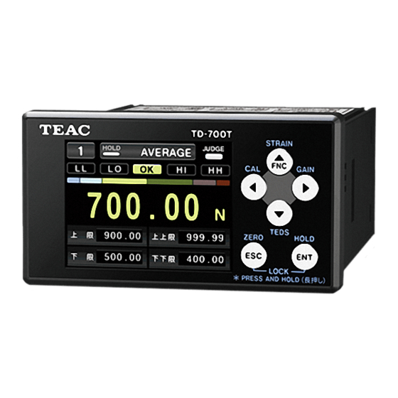
- Page 11 1. Names and functions of parts 1-1. Front panel Setting buttons ZERO/ESC button STRAIN When Cal. Value Lock is OFF, press and hold to use the Press and hold to open static strain display. Zero Balancing function (page 44). When Cal. Value Lock is ON, press this to forcibly set the Press and hold to conduct equivalent input calibration.
- Page 12 Connect the included GPE012T AC adapter. o See page 26 for information about compatible plugs. DC IN 12V o An AC adapter is included with the TD-700T for Japan and North America. No adapter is included for other regions. (The included AC adapter conforms to the safety stan- dards of Japan and North America.)
- Page 13 1. Names and functions of parts 1-3. Sensor signal input terminals 1-4. D/A output connectors These can output either voltage or current. +SENS/TEDS(F) They cannot output both at the same time. Set voltage or current in System Settings q D/A Converter q D/A Output Mode (page 75).
- Page 14 1. Names and functions of parts o Signals are input to each terminal by shorting and open- 1-5. Control signal input terminal ing with 18 COM. A current of about 20mA results from shorting. When using a transistor, select one with a resistance of Terminal Signal Explanation...
- Page 15 1. Names and functions of parts 1-7. Screen transition diagram Screen selected on the System Settings Home Screen page Power supply ON will open Standard Bar meter display Indicator Value Only Display Waveform display Function Menu Press and hold Actual Load Calibration Press and hold Equivalent Input...
- Page 16 1. Names and functions of parts 1-8-2. Bar meter display 1-8. Home Screen The screen selected on the System Settings Home Screen page will open when the unit is turned on. Use the g and t buttons to change screen views. NOTE The Home Screen will open about 15 seconds after power is supplied to the unit.
- Page 17 1. Names and functions of parts Memory number High limit, low limit, high high limit and The currently selected memory number is shown. low low limit setting values Each setting value is shown. HOLD indicator If high high limit and low low limit are disabled, the LOCK When the hold function is active, a white indicator settings are shown.
- Page 18 1. Names and functions of parts 1-8-4. Graph display The screen will appear as follows when the peak to peak hold or peak and bottom hold function is active. This graph shows the indicator value as the vertical axis and the time as the horizontal axis.
- Page 19 1. Names and functions of parts Hold indicator The color shows the hold status. White: hold activated Gray: zone definition activated No indicator: hold not activated Hold line This line corresponds to the hold value. This line is shown in purple. o Press the ESC button to initialize the hold value.
- Page 20 2. Installation Follow these procedures to install the unit in a control panel. Insert the unit through the front of the panel. 2-1. Installing in a panel Open a hole in the panel in accordance with this dimensional drawing of the panel installation opening.
Need help?
Do you have a question about the TD-700T and is the answer not in the manual?
Questions and answers