Table of Contents
Advertisement
Quick Links
https://wiki.teltonika-gps.com/view/FMU130_First_Start
FMU130 First Start
Main Page
>
EOL Products
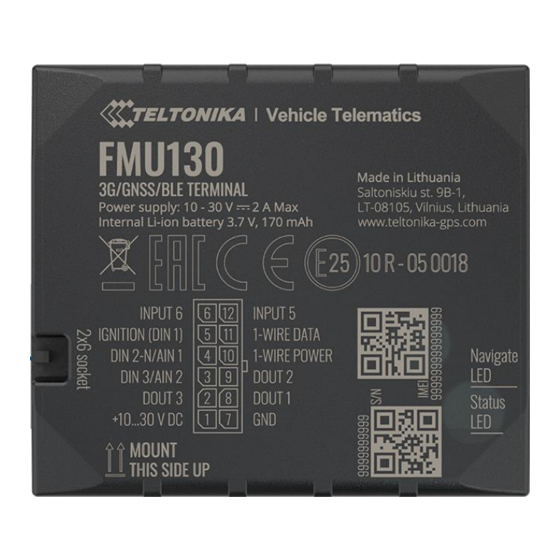
GNSS/GSM/Bluetooth tracker with internal GNSS/GSM antennas and internal battery
Contents
1 How to insert Micro-SIM card and connect the battery
How to insert Micro-SIM card and connect the battery
1.
Gently remove FMU130 cover using plastic pry tool from both sides.
2.
Insert Micro-SIM card as shown with PIN request disabled or read
enter it later in Configurator. Make sure that Micro-SIM card cut-off corner is pointing
forward to slot.
Attach device cover back.
3.
4.
Device is ready to be connected.
Micro-SIM card insertion/removal must be performed when device is powered off –
external voltage and internal battery disconnected. Otherwise Micro-SIM card might be
damaged or device will not detect it.
Battery placement after complete device disassembling
>
FMU130
> FMU130 First Start
Security info
how to
Advertisement
Table of Contents

Related Manuals for Teltonika FMU130


Summary of Contents for Teltonika FMU130
- Page 1 5 Safety information 5.1 Precautions How to insert Micro-SIM card and connect the battery Gently remove FMU130 cover using plastic pry tool from both sides. Insert Micro-SIM card as shown with PIN request disabled or read Security info how to enter it later in Configurator.
- Page 2 Data for 1–Wire devices. INPUT 5 RX EXT (LVCAN - RX). PC Connection (Windows) Power-up FMU130 with DC voltage 10-30 V power supply using supplied power cable. LED’s should start blinking, see “FMU130 LED status”. Connect device to computer using Micro-USB cable or Bluetooth connection:...
- Page 3 Setup will continue installing the driver and eventually the confirmation window will appear. Click Finish to complete the setup. Configuration (Windows) At first FMU130 device will have default factory settings set. These settings should be changed according to the user's needs. Main configuration can be performed via Teltonika Configurator software.
- Page 4 Various and etc. FMU130 has one user editable profile, which can be loaded and saved to the device. After any modification of configuration the changes need to be saved to device using Save to device button. Main buttons offer following functionality: Load from device –...
- Page 5 If device has made a record it is sent to the server every 120 seconds After successful SMS configuration, FMU130 device will synchronize time and update records to configured server. Time intervals and default I/O elements can be changed by using Teltonika Configurator parameters.
- Page 6 Installation photos FMU130 is the device that has internal GNSS and GSM antenna. Device should be mounted with the sticker / engraving view to the open sky (metal free). FMU130 area with engraving is shown in figure below: FMU130 can be mounted under the plastic panel behind the front window, with the sticker / engraving direction to a window (sky).
- Page 7 The device is designed to be mounted in a zone of limited access, which is inaccessible to the operator. All related devices must meet the requirements of EN 60950-1 standard. The device FMU130 is not designed as a navigational device for boats. Precautions Do not disassemble the device.
Need help?
Do you have a question about the FMU130 and is the answer not in the manual?
Questions and answers