Table of Contents
Advertisement
Quick Links
Advertisement
Table of Contents

Subscribe to Our Youtube Channel
Related Manuals for Teltonika FMB964


Summary of Contents for Teltonika FMB964
- Page 1 FMB964 Quick Manual Special and smart tracker v1.0...
-
Page 2: Table Of Contents
How to install USB drivers (Windows) ..........7 Configuration (Windows) ..............7 Quick SMS configuration ..............9 Mounting recommendations ............. 10 LED indications ................11 Characteristics................11 Basic characteristics ............... 11 Electrical characteristics ..............13 Safety information ..............14 Certification and Approvals ............15 FMB964 | Wiki... -
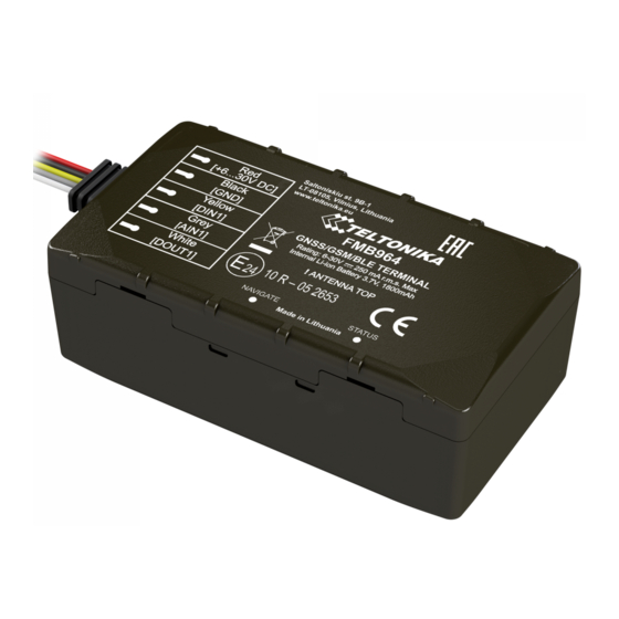
Page 3: Know Your Device
Know your device Figure 1 FMB964 device view FMB964 | Wiki... -
Page 4: Pinout
(Black) Ground (Yellow) Digital input, channel 1. DIN1 DEDICATED FOR IGNITION INPUT (Grey) Analog input, channel 1. Input AIN1 range: 0-30 V DC (White) Digital output. Open collector DOUT1 output. Max. 3,3 A DC. Figure 2 FMB964 pinout FMB964 | Wiki... -
Page 5: Wiring Scheme
Wiring scheme Figure 3 FMB964 Wiring scheme Automotive relay FMB964 | Wiki... -
Page 6: Set Up Your Device
Set up your device How to insert Micro-SIM card 1. Gently remove FMB964 cover using plastic pry tool from both sides. 2. Insert Micro-SIM card as shown with PIN request disabled or read our Wiki how to enter it later in Teltonika Configurator. -
Page 7: Pc Connection (Windows)
Setup will continue installing the driver and eventually the confirmation window will appear. Click Finish to complete the setup. 1. Power-up FMB964 with DC voltage (6 – 30 V) power supply using power wires. LED’s should start blinking, see “LED Configuration (Windows) indications”. - Page 8 Most important configurator section is GPRS – where all your server and GPRS settings can be configured and Data Acquisition – where data acquiring parameters can be configured. More details about FMB964 configuration using Configurator can be found in our Wiki. Figure 10 Configurator Status window FMB964 | Wiki...
-
Page 9: Quick Sms Configuration
2006 – Data sending protocol After successful SMS configuration, FMB964 device will (0 – TCP, 1 – UDP) synchronize time and update records to configured server. Time intervals and default I/O elements can be changed by using Teltonika Configurator parameters. -
Page 10: Mounting Recommendations
▬ Use 3A, 125V external fuse. and dynamic potentials on the line GND will be unpredictable, which can lead to unstable FMB964 operation and even its failure. FMB964 | Wiki... -
Page 11: Led Indications
Device is not working or Device is in boot mode Technology Quad-band 850 / 900 / 1800 / 1900 2G bands GPRS Multi-Slot Class 12 (up to 240 Data transfer kbps), GPRS Mobile Station Class B Data support SMS (text/data) FMB964 | Wiki... - Page 12 OBDII dongle Micro-SIM Digital Input 1, Accelerometer, External Memory 128MB internal flash memory Ignition detection Power Voltage, Engine RPM (OBDII Physical specification dongle) Dimensions 79 x 43 x 27.5 mm (L x W x H) Weight 98 g FMB964 | Wiki...
-
Page 13: Electrical Characteristics
Drain current (Digital Output OFF) Measurement error on 30V Drain current (Digital Output ON, Additional error on 30V Recommended Operating Conditions) Static Drain-Source resistance (Digital Output mΩ Digitial Input Input resistance (DIN1) kΩ Input voltage (Recommended Operating Conditions) Input Voltage threshold FMB964 | Wiki... -
Page 14: Safety Information
All related devices must meet the requirements of EN 60950-1 standard. The device is susceptible to water and humidity. The device FMB964 is not designed as a navigational device for boats. FMB964 | Wiki... -
Page 15: Certification And Approvals
This sign on the package means that all used electronic and electric equipment should not be mixed with general household waste. Hereby, Teltonika declare under our sole responsibility that the above described product is in conformity with the relevant Community harmonization: European Directive 2014/53/EU (RED). -
Page 16: Warranty
Repaired More information can be found at teltonika.lt/warranty-repair Replaced with a new product Replaced with an equivalent repaired product fulfilling the same functionality TELTONIKA can also repair products that are out of warranty at an agreed cost. FMB964 | Wiki...
Need help?
Do you have a question about the FMB964 and is the answer not in the manual?
Questions and answers