Table of Contents

Related Manuals for Innova AirLeaf ECB649


Summary of Contents for Innova AirLeaf ECB649
- Page 1 All manuals and user guides at all-guides.com Installation manual D C I n v e r t e r ECA644 - ECA647 - EWF644 - EWF647 - ESD645 - ESD648 ECA649 - ECB649 - EWF649 - EWB649 E4T643 - E2T543 - B3V137 B4V642 - B3V151- B3V152 - B10642...
- Page 2 By following the suggestions contained in this manual, the product you have purchased will operate without problems, giving you optimum room temperatures with minimum energy costs. Innova S.r.l Symbols The pictograms in the next chapter provide the necessary unmistakable way.
-
Page 3: Table Of Contents
All manuals and user guides at all-guides.com General table of contents GENERAL General warnings ................5 ECA644 - ECA647 - ESD645 - ESD648 Assembly, set-up and connection of on-board control panels ECA644, ESD645, ECA647, ESD648. - Page 4 All manuals and user guides at all-guides.com B10642 11.1 Assembly and fitting of fan control for remote control B10642..........28 11.2 Assembly .
-
Page 5: General Warnings
All manuals and user guides at all-guides.com GENERAL General warnings This instruction is an integral part of the booklet of It is forbidden to modify the safety or adjustment the appliance on which the kit is installed. Please consult devices without authorisation from and indications of the this booklet for general warnings and fundamental safety manufacturer. -
Page 6: Assembly, Set-Up And Connection Of On-Board Control Panels Eca644, Esd645, Eca647, Esd648
All manuals and user guides at all-guides.com ECA644 - ECA647 -EWF644 - EWF647 - ESD645 - ESD648 Assembly, set-up and connection of on-board control panels ECA644, ESD645, ECA647, ESD648 The controllers have two independent clean contacts compartment on the battery regulations the minimum level for controlling a refrigerator unit, a boiler and a presence when heating (30°C) and the maximum level when cooling input. -
Page 7: Set-Up Of Auxiliary Dip-Switch Functions B And C
All manuals and user guides at all-guides.com Set-up of auxiliary dip-switch functions B and C There are two dip switches on the controller circuit board reached the set point, to allow for more uniform for configuring unit operation as per requirements. operation of the temperature probe and to avoid The night-time heating operation logic is modified by layering in the air. -
Page 8: Air Temperature Probe Assembly (Only For Models Eca644, Eca647)
All manuals and user guides at all-guides.com Air temperature probe assembly (only for models ECA644, ECA647) To position the temperature probe (ref. A): insert the probe into the lower hole (ref. C) pass the probe through the hole on the shoulder (ref. B) fix the probe on the relevant hook (ref. -
Page 9: Eca644 And Eca647 Connections
All manuals and user guides at all-guides.com ECA644 and ECA647 connections water temperature probe (10 kΩ) boiler consent output (free contact max 1A) water temperature probe 4 pipes (10 kΩ) (only chiller consent output (free contact max 1A) for ECA 647) air temperature probe (10 kΩ) presence input sensor (if closed, the fan coil unit DC inverter fan motor... -
Page 10: Esd645 And Esd648 Connections
All manuals and user guides at all-guides.com ESD645 and ESD648 connections serial connection for wall-mounted remote chiller consent output (free contact max 1A) +BA- control ECA/ECB649 - EWF/EWB649 (respect AB polarity) RS water probe (10 kΩ) (ESD645 only) H2** hot water temperature probe (10 kΩ) Air probe optional (*) H4** cold water temperature probe (10 kΩ) (648 only) -
Page 11: Continuous Modulation Circuit Board For Connecting Remote Thermostat (Only For Models Esd645 - Esd648)
All manuals and user guides at all-guides.com Continuous modulation circuit board for connecting remote thermostat (only for models ESD645 - ESD648) The circuit board for remote control is for all functions of the room temperature are transmitted from the wall- the fan coil system from the wall-mounted remote control mounted remote control ECA/ECB649 - EWF/EWB649 ECA/ECB649 - EWF/EWB649. -
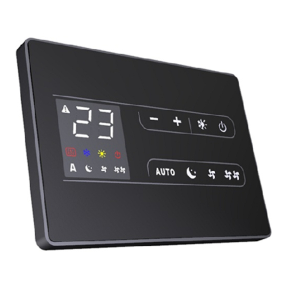
Page 12: Wall-Mounted Remote Control Panel Assembly Eca649 - Ecb649
All manuals and user guides at all-guides.com ECA649 - ECB649 Wall-mounted remote control panel assembly ECA649 - ECB649 The wall-mounted remote control ECA/ECB649 is an protruding teeth on the rear (A). electronic thermostat (fitted with an optional temperature Use the base of the controller (ref. B in diagram) to trace probe which can be remotely installed in one of the fan the fixing points on to the wall (use two opposing holes). -
Page 13: Cp Occupancy Contact Input Connection
All manuals and user guides at all-guides.com 0.2-1 mm CP occupancy contact input connection On closing the contact connected to the CP input (ref. The input cannot be connected in parallel to that A) the panels are placed into stand-by. If the contact is of other electronic boards (use separate contacts). -
Page 14: Wall-Mounted Remote Control Panel Assembly Ewb649 - Ewf649
All manuals and user guides at all-guides.com EWF649 - EWB649 Wall-mounted remote control panel assembly EWB649 - EWF649 The wall-mounted remote control EWB/EWF649 is an Use the base of the controller (ref. B in diagram) to trace electronic thermostat (fitted with an optional temperature the fixing points on to the wall (use two opposing holes). -
Page 15: Spring-Loaded Terminal Connections -Ab+ And Cp
All manuals and user guides at all-guides.com Spring-loaded terminal connections -AB+ and CP Rigid or flexible wires with a 0.2 to 1 mm² cross-section easily, whereas with flexible cable it may be easier to can be inserted in the spring-loaded terminal blocks for use a long pointed pair of pliers to insert correctly. -
Page 16: Ewb649 - Ewf649 Connections
All manuals and user guides at all-guides.com EWB649 - EWF649 Connections The wall-mounted remote control EWB/EWF649 is Rigid or flexible wires with a 0.2 to 1 mm² cross-section supplied with a serial expansion card M5/B30 + 12V (0.75 mm² if two wires are connected to the same terminal (cod. -
Page 17: E4T643
All manuals and user guides at all-guides.com E4T643 Assembly and connections for on-board control panel E4T643 The on-board controller is a panel with 8 capacitative keys for installing on board and has a 230V output for controlling and amber display that contains the AUTO function (step a solenoid valve. -
Page 18: Air Temperature Probe Assembly
All manuals and user guides at all-guides.com Air temperature probe assembly To position the temperature probe (ref. A): insert the probe into the lower hole (ref. C) pass the probe through the hole on the shoulder (ref. B) fix the probe on the relevant hook (ref. D) E4T643 Connections water temperature probe (10 kΩ) RS water probe (10 kΩ) -
Page 19: E2T543
All manuals and user guides at all-guides.com E2T543 Assembly and connections for on-board control panel E2T543 The on-board controller with speed selector and ON/OFF (30°C) and maximum summer temperature (20°C) is suitable key, room thermostat adjustable from 5 to 40°C, winter for fitting on board the unit and has a 230V - 1A output for summer selector and minimum winter temperature function controlling a solenoid valve. -
Page 20: Air Temperature Probe Assembly
All manuals and user guides at all-guides.com Air temperature probe assembly To position the temperature probe (ref. A): insert the probe into the lower hole (ref. C) pass the probe through the hole on the shoulder (ref. B) fix the probe on the relevant hook (ref. D) E2T543 Connections water temperature probe (10 kΩ) RS version cabling... -
Page 21: B3V137
All manuals and user guides at all-guides.com B3V137 Assembly and connections for on-board control panel B3V137 The on-board controller with speed selector and ON/OFF key unit and has a 230V output for controlling a solenoid valve. and TERM room thermostat is suitable for fitting on board the Assembly Slide the control panel into its housing in the upper part N.B.: should the two brown terminals on the unit be... -
Page 22: B3V137 Connections
All manuals and user guides at all-guides.com B3V137 Connections 230V connection permission from room 230V/50Hz electrical power supply thermostat RS version cabling DC inverter fan motor output for mobile suction panel servo (power grill safety micro-switch output 230V/ 50Hz 1A) water solenoid valve (230V/ 50Hz 1A output water probe for RS version (10 kΩ) voltage) -
Page 23: B4V642
All manuals and user guides at all-guides.com B4V642 Assembly and fitting of fan control for remote control B4V642 Assembled on-board the unit, this card allows the regulation available in the market. of the motor with fixed speeds; it can be combined with It has a 230 V output to pilot the summer and winter solenoid control panels with thermostat and with all control panels valve. -
Page 24: Connection Diagram B4V642 With 3-Speed Thermostat
All manuals and user guides at all-guides.com Connection diagram B4V642 with 3-speed thermostat make the electrical connections to a thermostat fit for use according to the diagram electrical supply 230V-50Hz water probe for RS (10 kΩ) solenoid valve permission input DC inverter fan motor maximum fan speed safety micro-switch for grill... -
Page 25: Led Signals
All manuals and user guides at all-guides.com LED signals The LED (ref. A) is off if the CV input is not closed (stand-by • 3 flashes + pause indicates a disconnected or faulty condition). water probe alarm. It turns on when the CV contact is closed and indicates normal operation. -
Page 26: B4V642 + B3V151 Connection Diagrams
All manuals and user guides at all-guides.com B4V642 + B3V151 B4V642 + B3V151 Connection Diagrams Wall control with thermostat, summer/winter selector and For 2-pipe units. speed selector in connection with B4V642. Electrical power supply 230V-50 Hz Mobile suction panel commander (power output Permission input 230V/ 50Hz 1A) RS version cabling... -
Page 27: B4V642 + B3V152
All manuals and user guides at all-guides.com B4V642 + B3V152 10.1 B4V642 + B3V152 Connection Diagrams Built-in wall control with thermostat, summer/winter For 2-pipe units. selector and speed selector in connection with B4V642. Electrical supply 230V-50Hz Mobile suction panel commander (power output Permission input 230V/ 50Hz 1A) RS version cabling... -
Page 28: B10642
All manuals and user guides at all-guides.com B10642 11.1 Assembly and fitting of fan control for remote control B10642. When fitted on board the machine it allows for managing the For board B10642 control outputs these impedance values motor, with modulated speed; motor regulation can be made must be considered, especially when controlling more than using an analogue 0-10V DC input with 25 kΩ... -
Page 29: Connection Diagram B10642 With 0-10V Dc Thermostats / Signals
All manuals and user guides at all-guides.com 11.4 Connection diagram B10642 with 0-10V DC thermostats / signals make the electrical connections to a thermostat fit for use according to the diagram Electrical power supply 230V-50 Hz RS version cabling Appliance piloting input 0÷10 V water probe for RS (10 kΩ) water solenoid valve (230V/ 50Hz 1A output DC inverter fan motor... -
Page 30: Ed Rs Full Flat Versions
All manuals and user guides at all-guides.com ED RS FULL FLAT VERSIONS 12.1 Full flat version connections In this version, the servo mechanisms charged with moving the grill are pre-wired to the unit. They can be connected to the Y2 output on the panels using a dedicated connector (ref. -
Page 31: Versions With Connections On The Right
All manuals and user guides at all-guides.com VERSIONS WITH CONNECTIONS ON THE RIGHT 13.1 Motor connection in versions with hydraulic connections on the right BB0646 Should the battery hydraulic connection positions need to Furthermore, the two terminals connected to the grill safety be inverted from the left to the right hand side of the unit, micro switch are extended and connected on the left hand the electrical connection box is also inverted, but as the fan... - Page 32 All manuals and user guides at all-guides.com INNOVA s.r. l . INNOVA s.r.l. Fraz . St rada, 16 - 38085 PIEVE DI BONO (TN) - ITALY Via I Maggio, 8 - 38089 Storo (TN) - ITALY tel. +39.0465.670104 fax +39.0465.674965 tel.
Need help?
Do you have a question about the AirLeaf ECB649 and is the answer not in the manual?
Questions and answers