Innova AirLeaf ECA644 User Manual
Dc inverter
Hide thumbs
Also See for AirLeaf ECA644:
- Installation manual (40 pages) ,
- User manual (24 pages) ,
- Installation manual (32 pages)

Related Manuals for Innova AirLeaf ECA644


Summary of Contents for Innova AirLeaf ECA644
- Page 1 User manual D C I n v e r t e r ECA644 - ESD645 - ECA649 - ECA647 - ESD648 EWF644 - EWF647 - E4T643 - E2T543 - B3V137 B4V642 - B10642 - BM1151- BM0152...
- Page 2 By following the suggestions contained in this manual, the product you have purchased will operate without problems, giving you optimum room temperatures with minimum energy costs. Innova S.r.l This booklet code N273005E - Rev. 00 - (09/18) consists of 44 pages.
-
Page 3: Table Of Contents
General table of contents GENERAL General waenings ..............6 Fundamental safety rules ... - Page 4 E4T643 SMART TOUCH electronic control panel with fixed speed modulation ......15 Display ............... . 15 Key function ...
- Page 5 TROUBLESHOOTING Troubleshooting ..............28 Troubleshooting table ...
-
Page 6: General Waenings
GENERAL General waenings This instruction is an integral part of the booklet of the It is forbidden to modify the safety or adjustment appliance on which the kit is installed. Please consult devices without authorisation from and indications of the this booklet for general warnings and fundamental safety manufacturer. -
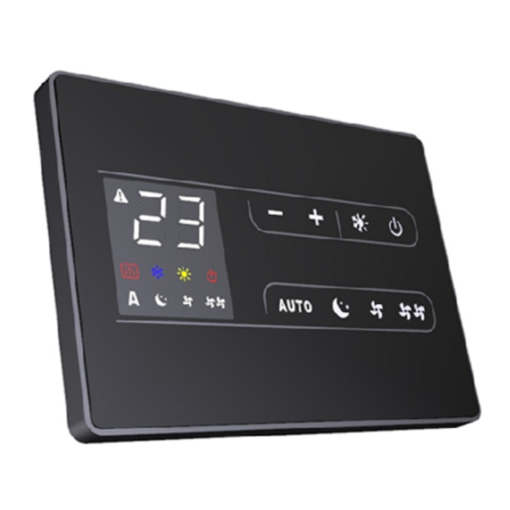
Page 7: Eca644 - Eca647 - Ewf644 - Ewf647
ECA644 - ECA647 - EWF644 - EWF647 SMART TOUCH electronic control panel with device side continuous modulation These controls make room temperature adjustment (with After 20 seconds from the last action the panel offset settable from the keyboard) completely autonomous brightness will be reduced for improved night-time through the AUTO, SILENT, NIGHT and MAX programmes comfort, and the room temperature will appear on the... -
Page 8: General On Switch
General On Switch In order to manage the device via the control panel, this also be switched on. must be connected to the mains electricity. - Turn the device on by activating the general switch If a general switch is installed on the power line, this must Activation To activate the device Operation... -
Page 9: Automatic Operation
Automatic operation Operation Display Press and hold the AUTO key. The function being activated is indicated by the relevant symbol appearing on the display. Ventilation speed adjustment is carried out automatically point, according to a PI-type algorithm. between the minimum and maximum values, according to the distance of the actual room temperature from the set 2.10 Silent operation... -
Page 10: Deactivation
2.15 Deactivation Operation Display Press and hold the ON Stand-By key for approx. 2 seconds. No illuminated signals on the display at all means that the system is in stand-by (no operation). The controller also ensures anti freezing when in stand-by. 2.16 Room temperature probe regulation offset As the detection probe is towards the bottom of the... -
Page 11: Eca649
ECA649 Wall-mounted SMART TOUCH electronic control panel with room probe The remote wall-mounted control ECA649 is an electronic Anti-freeze protection guaranteed thermostat with a room temperature probe for controlling temperature probe when in stand-by. one or more (up to a maximum of 30) fan coils / cooler- radiators in broadcast mode (with simultaneous control After 20 seconds from the last action, the panel transmission) equipped with electronic control for ESD645... -
Page 12: General On Switch
General On Switch In order to manage the device via the control panel, this also be switched on. must be connected to the mains electricity. - Turn the device on by activating the general switch If a general switch is installed on the power line, this must Activation To activate the device Operation... -
Page 13: Automatic Operation
Automatic operation Operation Display Press and hold the AUTO key. The function being activated is indicated by the relevant symbol appearing on the display. Ventilation speed adjustment is carried out automatically point, according to a PI-type algorithm. between the minimum and maximum values, according to the distance of the actual room temperature from the set 3.10 Silent operation... -
Page 14: Deactivation
3.15 Deactivation Operation Display Press and hold the ON Stand-By key for approx. 2 seconds. No illuminated signals on the display at all means that the system is in stand-by (no operation). The controller also ensures anti freezing when in stand-by. 3.16 Room temperature probe regulation offset As the detection probe is towards the bottom of the... -
Page 15: E4T643
E4T643 SMART TOUCH electronic control panel with fixed speed modulation These controls make room temperature adjustment (with brightness will be reduced for improved night-time offset settable from the keyboard) completely autonomous comfort, and the room temperature will appear on the through the four speeds by means of a probe located in display. -
Page 16: General On Switch
General On Switch In order to manage the device via the control panel, this also be switched on. must be connected to the mains electricity. - Turn the device on by activating the general switch If a general switch is installed on the power line, this must Activation To activate the device Operation... -
Page 17: Ventilation Speed Regulation
Ventilation speed regulation Operation Display The fan speed is selected by using one of the 4 keys (automatic, minimum, super silent and maximum). The activation of the function is indicated by the relevant symbol on the display. In automatic mode, the fan carries out a "stepped" power level is activated immediately whether heating or adjustment to move the room temperature closer to the cooling. -
Page 18: Room Temperature Probe Regulation Offset
4.13 Room temperature probe regulation offset As the detection probe is towards the bottom of the actually detected a discrepancy compared with the actual device, the temperature detected may at times differ from room temperature using a reliable device! the actual room temperature. By using this function, the value displayed can be adjusted in a range from -9 to +12 K in intervals of 1°C. -
Page 19: E2T543
E2T543 4-speed on board LCD electronic control panel The controller makes the regulation of room temperature entirely automatic using the set point setting which can be After 20 seconds from the last action, the panel adjusted between 5°C and 40°C, to one of the 4 speeds brightness will be reduced for improved night-time and the summer/winter setting. -
Page 20: Activation
Activation To activate the device Operation Display Off → On Press the mode/off key Select one of the 4 operating speeds by pressing the relative mode/off key. When heating, the symbol displays when the set point is higher than ambient temperature, both are off when the set point is lower. -
Page 21: Key Lock
5.10 Key lock Operation Display When the increase and decrease keys are pressed simultaneously for 5 seconds, all keys are locally locked; this is indicated by bL appearing on the display. All actions are disabled to the user and whenever any key is pressed, "LOC" will appear. To unlock the keys, repeat the sequence. -
Page 22: B3V137
B3V137 On-board speed selector for connecting to standard thermostat. The command is for switching on and off and selecting the 4 speeds directly from the fan coil. Controls cannot be installed on the SLI and RSI versions. Switching on and off takes place via closing of the external thermostat contact. -
Page 23: General On Switch
General On Switch To manage the fan coil via the selector, it must be also be switched on. connected to the mains and to a room thermostat with a - Turn the device on by activating the general switch single 230V AC contact. If a general switch is installed on the power line, this must Activation To activate the device... -
Page 24: Deactivation
Deactivation Operation Display Press and hold the mode/off key for approx. 2 seconds. No illuminated signals on the display at all means that the system is in stand-by (no operation). Switching off for long periods When switching off for a season or for holidays, proceed - Deactivate the device as follows: - Turn the general unit switch to off. -
Page 25: Maintenance
MAINTENANCE External cleaning Disconnect the unit from the power supply before Do not use abrasive sponges or abrasive or corrosive each cleaning and maintenance intervention by setting detergents as you might damage the painted surfaces. the main power supply switch to off. When necessary, clean the external surfaces of the fan Wait for the components to cool down in order to coil with a soft damp cloth. - Page 26 Removal of filtering cells in versions with mobile panel suction. Pass hand underneath the far side of the mobile panel Lift and extract the mobile panel Press the plastic tabs Extract the filter. Mobile panel Filter Plastic tabs Filter extraction Cleaning the filters Remove dust from the filter with a vacuum cleaner Do not use the device without the mesh filter.
-
Page 27: Suggestions For Power Saving
Complete cleaning operations For versions with a flap grill, insert the two tabs in the corresponding loops, rotate and attach with a light tap to the upper section. Tabs Loops For versions with a mobile panel, rest in position parallel to the front and press until locked into place. Suggestions for power saving Ensure filters are constantly clean;... -
Page 28: Troubleshooting
TROUBLESHOOTING Troubleshooting Ventilation does not start even if there is hot or cold In the event of water leaks or anomalous operation, water in the hydraulic circuit. disconnect mains power immediately and close all The device leaks water when heating. water taps. -
Page 30: Innovapp Operation
InnovApp Fancoils for EWF644 - EWF647 Minimum system requirements The INNOVA Fancoils App lets you manage the main To download and install the app, there are some operating parameters of your fancoil using a smartphone and tablet system version requirements for your smartphone: from home or when you are out. - Page 31 After switching on the display of your fancoil, go to your telephone’s WiFi settings: ensure that you have activated WiFi check the available WiFi connections find the “Fancoil” network connect to it. Note: with Android devices, this procedure is automatic. With iOS devices, you must enter the WiFi settings of your device and select the “Fancoil”...
-
Page 32: App Features
DHCP / IP configuration of the network GROUPS list of groups of several fancoils (e.g. 1st floor, 2nd floor,...). PREFERENCES language and PUSH notifications Figure 9-11 MANUAL link to the INNOVA website where you can find the necessary documentation www.innovaenergie.com/en/documents-products-airconditioners-innova/ manuals/ HELPDESK to ask for support... -
Page 33: My Products
My Products MY PRODUCTS list of the fancoils and groups configured in the App By selecting the "My Products" item, you can see the fancoils on the network. They can be edited and/or scheduled as desired. New devices can be added, searching for, installing and configuring them tapping on the + symbol in the top right corner and/or at the bottom right. -
Page 34: Mode
Mode MODE list of possible fancoils management modes The fancoil operating mode can be changed in several ways: - selecting "Mode" in the general menu - clicking on the change button at the bottom right of the fancoil general screen (see section 9.4 on page 32 ). This provides access to the screen illustrated in Figure 9-16. -
Page 35: Scheduling
Scheduling SCHEDULING section dedicated to the weekly scheduling of the fancoil Note: this option is possible only if remote control has been configured (see section 9.9 on page 38 to enable remote control). By selecting the "Scheduling" item, access fancoil calendar scheduling feature. - Page 36 If you want to apply the same schedule that you have just confirmed for other days, simply click "copy" and select the days where you want to apply this schedule (as illustrated in the sequence of example figures shown below). Figure 9-24 Figure 9-25 Figure 9-26...
- Page 37 After completing scheduling, select the “Mode“ item in the general menu, then “Programming“. This activates the weekly program you just created. Returning to the fancoil's main screen (Figure9-31, on the lower part, there are the indication of the scheduling. If you was in the scheduled shut-down time, the time of the first fancoil restart will be showed in the lower part.
-
Page 38: Remote Access
Remote access REMOTE ACCESS manage your fancoil even away from home Once you have selected the menu item "Remote Access", a list of the available WiFi connections will appear. Note: the fancoil can connect only with 2.4GHz networks. Select the preferred network for Internet access.Then enter the WiFi network password and confirm it. -
Page 39: Groups
9.10 Groups GROUPS list of groups of several fancoils If you have several fancoils, you can combine them in groups to simplify scheduling and management of them. (For example, the fancoils in a hotel could be grouped by floor). First of all, select "Groups" in the menu and create a new group by clicking on "+". -
Page 40: Preferences
You can also associate a fancoil with the group through the fancoil itself. Select the penultimate icon on the row of the fancoil (icon list with three rows) and click "Assign groups" (Figure 9-42). Assign the fancoil to one of the groups shown on the list. -
Page 41: Control With Several Devices
9.12 Control with several devices CONTROL WITH SEVERAL DEVICES At this point, the telephone alerts that you are not The same fancoil can be managed with several devices connected to the right WiFi network and to connect to the (smartphone/tablet/PC). “Fancoil”: ignore the warning, clicking on the “devices”... -
Page 42: Troubleshooting
9.13 Troubleshooting Effect Causa Solution iOS smartphones do not automatically identify Go to the telephone's settings and select The fancoil cannot be configured on the iOS the WiFi network which was renamed during the fancoil unit's WiFi network with the name smartphone configuration of the App assigned to it during configuration of the App... - Page 44 INNOVA s.r. l . INNOVA s.r. l . Fraz . St rada, 16 - 38085 PIEVE DI BONO (TN) - ITALY Via I Maggio, 8 - 38089 Storo (TN) - ITALY tel. +39.0465.670104 fax +39.0465.674965 tel. +39.0465.670104 fax +39.0465.674965 info@innovaenergie.com info@innovaenergie.com...
Need help?
Do you have a question about the AirLeaf ECA644 and is the answer not in the manual?
Questions and answers