Table of Contents
Advertisement
Quick Links
Introduction
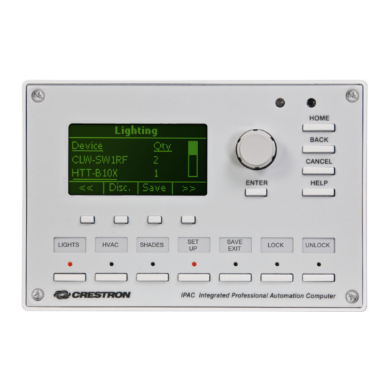
IPAC-GL1-W-T Physical View (shown in white)
Supplied Parts
Supplied Hardware for the IPAC
Mounting Plate with Ground Wire
Screws, 06-32 x ¾", Combo Head
Screws, 04-40 x ¼", Pan, Phil
Screws, 04-40, 7/16", Pan, Phil, Blk
(for Black units)
Screws, 04-40, 7/16", Pan, Phil, Zinc
(for White units)
Label Sheet
Front Cover
Crestron Electronics, Inc.
15 Volvo Drive Rockleigh, NJ 07647
Tel: 888.CRESTRON
Fax: 201.767.7576
www.crestron.com
This document contains instructions for installing the IPAC series of wall-mounted,
Integrated Professional Automation Computers.
The IPAC is designed for installation in a standard 3-gang electrical box.
The parts supplied with the IPAC are listed in the following table.
DESCRIPTION
OR
PART NUMBER
4506280
2009211
2007156
2022900
2013409
4505784 (Black) OR 4506570 (White)
4505711 (Black) OR 4505867 (White)
Installation Guide – DOC. 6696A
IPAC
QUANTITY
1
4
2
4
1
1
(2022187)
12.08
Specifications subject to
change without notice.
Advertisement
Table of Contents

Subscribe to Our Youtube Channel
Related Manuals for Crestron IPAC


Summary of Contents for Crestron IPAC
- Page 1 Introduction This document contains instructions for installing the IPAC series of wall-mounted, Integrated Professional Automation Computers. The IPAC is designed for installation in a standard 3-gang electrical box. IPAC-GL1-W-T Physical View (shown in white) Supplied Parts The parts supplied with the IPAC are listed in the following table.
-
Page 2: Installation
Integrated Professional Automation Computer Installation The following tools are required for installation of an IPAC: Install the Mounting Plate Use the four included 06-32 x ¾” screws to install the mounting plate on the electrical box. Refer to the diagram below. -
Page 3: Network Device
Crestron IPAC WARNING: Prior to connecting the IPAC, turn off power at the power supply. Failure to do so may result in serious personal injury or damage to the device. Restore power after all connections have been made. When making connections to the IPAC, note the following: NOTE: The IPAC can only be powered by either of the 4-position NET connectors. - Page 4 Integrated Professional Automation Computer LAN Connector The following illustration shows the pin assignments of the RJ-45 LAN connector. WARNING: Incorrect wiring may damage the IPAC. COM Connector Refer to the illustration below when wiring the COM connector. WARNING: Incorrect wiring may damage the IPAC.
- Page 5 Crestron IPAC RELAYS Connector Refer to the illustration below when wiring the RELAYS connector. WARNING: Incorrect wiring may damage the IPAC. INPUTS Connector The illustration below is an example of what could be connected to the INPUTS connector. WARNING: Incorrect wiring may damage the IPAC.
- Page 6 Integrated Professional Automation Computer Attach the IPAC to the Mounting Plate Use the two included 04-40 x ¼” screws to attach the IPAC to the mounting plate as shown in the following diagram. CAUTION: Excess wire that is pinched between the IPAC and the electrical box could short out.
- Page 7 As shown in the following diagram, attach the label holder by placing the holder tabs in the slots and sliding them downward into position. Attach the Faceplate to the IPAC Use the included 04-40, 7/16” screws to attach the faceplate to the IPAC as shown in the following diagram. SCREWS (4) 04-40 x (2022900 or 2013409) Installation Guide –...
-
Page 8: Specifications
0.40 in 5.25 in (11 mm) (134 mm) 6.70 in (171 mm) 0.33 in 6.04 in (9 mm) (154 mm) 8 • Integrated Professional Automation Computer: IPAC IPAC Specifications (Continued) SPECIFICATION Environmental Temperature ® Humidity Heat Dissipation Enclosure Faceplate Chassis... -
Page 9: Industry Compliance
This unit has been manufactured to comply with UL’s Standards for Safety in Canada and the United States. Formal approval is pending. As of the date of manufacture, the IPAC has been tested and found to comply with specifications for CE marking. -
Page 10: Problem Solving
The following table provides corrective action for possible trouble situations. If further assistance is required, please contact a Crestron customer service representative. IPAC Troubleshooting For issues encountered during operation, refer to the latest version of the IPAC-GL1 Setup Guide (Doc. 6660) which can be downloaded from the Crestron website (www.crestron.com/manuals). - Page 11 Crestron IPAC Integrated Professional Automation Computer Appendix The following labels are included with the IPAC: 3-Phase Power Loss Sensor: IPAC • 11 Installation Guide – DOC. 6696A...
-
Page 12: Return And Warranty Policies
All brand names, product names and trademarks are the sole property of their respective owners. Windows is a registered trademark of Microsoft Corporation. Windows95/98/Me/XP/Vista and WindowsNT/2000 are trademarks of Microsoft Corporation. 12 • Integrated Professional Automation Computer: IPAC Crestron IPAC...
Need help?
Do you have a question about the IPAC and is the answer not in the manual?
Questions and answers