Table of Contents
Advertisement
Advertisement
Table of Contents
Troubleshooting

Subscribe to Our Youtube Channel
Related Manuals for Crestron MC2E


Summary of Contents for Crestron MC2E
- Page 1 Crestron MC2E 2-Series Professional Media Controller Operations Guide...
- Page 2 This document was prepared and written by the Technical Documentation department at: Crestron Electronics, Inc. 15 Volvo Drive Rockleigh, NJ 07647 1-888-CRESTRON All brand names, product names and trademarks are the property of their respective owners. ©2003 Crestron Electronics, Inc.
-
Page 3: Table Of Contents
Establishing Communication with the MC2E ... 15 Troubleshooting Communications ... 18 Compiling and Uploading a Program to the Control System ... 19 Uploading Web pages to the MC2E ... 20 Uploading Touchpanel Projects via the MC2E ... 21 Updating the Operating System... 22 Advanced Console Commands... -
Page 5: 2-Series Professional Media Controller: Mc2E
As with all of the Crestron 2-Series control processors, the 2-Series control engine is a solutions-driven control technology that is at the very heart of the MC2E. The breakthrough 2-Series control engine is based on the 257 MIPS, 32-bit Motorola... -
Page 6: Master Mode
IR, serial, Cresnet or Ethernet devices. Slave Mode In slave mode, the MC2E operates as a Cresnet device as part of a 2-series control system. For example, the MC2E can be part of a control system that includes IR, serial, Cresnet and Ethernet devices, with touchpanels that operate the MC2E through another 2-Series control system. -
Page 7: Physical Description
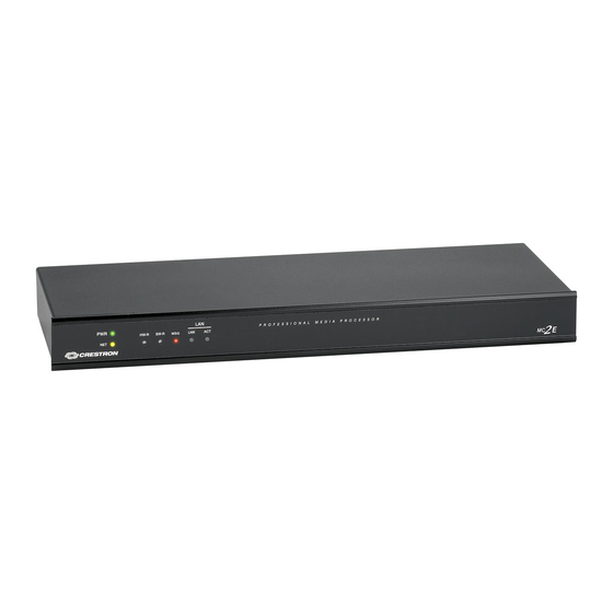
MC2E Specifications (continued) Physical Description The MC2E is housed in a black enclosure with labeling on the front and rear panels. The front panel includes standard LEDs and two reset buttons. All connections to the unit are made through the rear panel. Refer to the following illustrations. -
Page 8: Controls And Indicators
24VDC male receptacle for power supplied through an external power pack (included). The MC2E can be placed in a rack (with included mounting ears) or on a table with the supplied rubber feet. Refer to “Rack Mounting” on page 11 for more information. - Page 9 The CNXRMIRD that ships from Crestron requires some modification before use with the MC2E. THE CNXRMIRD ships with a mini phone jack that cannot be used with the 3-position connector on the IR IN port of the MC2E. To modify the CNXRMIRD to connect to the MC2E: Operations Guide –...
- Page 10 NOTE: Data Set Ready (DSR) and Data Terminal Ready (DTR) are not supported. 6 • 2-Series Professional Media Controller: MC2E 2. Using a voltmeter, determine which wire connects to the Tip, Ring, and Shield of the mini phone jack.
- Page 11 ABBREVIATION DESCRIPTION Data Carrier Detect Receive Data Transmit Data Data Terminal Ready Signal Ground Data Set Ready Request To Send Clear To Send Ring Ring Indicator 2-Series Professional Media Controller: MC2E • 7 DESCRIPTION Male DB9 Connector Female DB9 Connector...
- Page 12 This connector is used for expansion to Cresnet peripherals. This connector can also serve as a 24V power source to Cresnet devices when the MC2E is powered by the 24 Y Z G external power pack, PW-2410RU;. There is a 14 Watt maximum load rating for the Cresnet power output when used with the included power pack PW-2410RU.
-
Page 13: Memory
NOTE: Interface connectors for the NET, Infrared-Serial, I/O, and Relay Output ports are provided with the unit. 24VDC, 2.0A (Power Supply) This female connector can be used to supply 24 VDC power to the MC2E from the 24VDC included external power pack, (model PW-2410RU) or the optional power pack 2.0A... - Page 14 NOTE: If you extract NVRAM values to a file (creating an NVRAM disk via the Crestron Viewport command, File transfer | Save NVRAM to File), to simplify restoring them in the event of file corruption or to distribute to identical control systems, remember that NVRAM values are position sensitive in the program.
-
Page 15: Industry Compliance
Crestron MC2E Industry Compliance As of the date of manufacture, the MC2E has been tested and found to comply with specifications for CE marking and standards per EMC and Radiocommunications Compliance Labelling (N11785). NOTE: This device complies with part 15 of the FCC rules. Operation is subject to... -
Page 16: Bussing Strip Installation
(linking) of multiple terminal block connections on the relay port. One strip is supplied for the 8-position terminal block (four relays). 12 • 2-Series Professional Media Controller: MC2E 2. Position a rack ear so that its mounting holes align with the holes vacated by the screws in step 1. -
Page 17: Network Wiring
To power additional devices from the MC2E’s NET connector, use the optional power pack PW-2420RU that can supply up to 38 Watts from the NET connector to Cresnet devices. -
Page 18: Hardware Hookup
The ratings on the connecting unit's supply input should be considered to prevent overloading the wiring. Hookup Connections for the MC2E 14 • 2-Series Professional Media Controller: MC2E RESISTANCE (R) WIRE GAUGE Doubled CAT5... -
Page 19: Power Supply
2410RU, the MC2E can provide power to peripheral Cresnet devices (via the NET connector) up to a total of 14 Watts. The PW-2420RU allows the MC2E to provide up to 38 Watts to peripheral Cresnet devices (via the NET connector). - Page 20 The PC communication settings specified here should match the protocol that the MC2E ships with. The settings are as follows: “Port Settings” Window: Default PC Settings for RS-232 Communication with the MC2E To verify communication, click Diagnostics | Establish Communications (Find Rack).
-
Page 21: Tcp/Ip Connection
For TCP/IP, use CAT5 straight through cables with 8-pin RJ45 connectors to connect the LAN port on the MC2E and the LAN port on the PC to the Ethernet hub. Alternatively, you can use a CAT5 crossover cable to connect the two LAN ports directly, without using a hub. -
Page 22: Troubleshooting Communications
(e.g., for a modem). Consult the manufacturer’s documentation for further information about the COM ports on your 3. Check the ERR LED indicator on the front panel of the MC2E. If this LED is illuminated before a program is loaded, unplug the unit and reapply power after a few seconds. -
Page 23: Compiling And Uploading A Program To The Control System
Compiling and Uploading a Program to the Control System After you have completed your SIMPL Windows program using an MC2E, you must compile and upload the program to the control system. To compile the program, simply click the Convert/Compile button SIMPL Windows toolbar, or select Project | Convert/Compile (you can also press F12). -
Page 24: Uploading Web Pages To The Mc2E
In designing and creating a browser project, keep in mind that you must assign an IP ID to all the project pages and specify the IP address of the MC2E. (For further information on this procedure, refer to the VT Pro-e online help file.) -
Page 25: Simpl Windows
As with all Ethernet devices, the PC Interface must receive an entry in the IP Table of the MC2E. Here the IP ID must match the IP ID that was assigned in VT Pro-e, while the IP address must be set to a loopback: 127.0.0.1, when hosting to the internal memory of the MC2E. -
Page 26: Updating The Operating System
The SIMPL Windows online help file provides a full listing of console commands that are valid for 2-Series control systems. You can access the MC2E console in a variety of ways: via a serial connection (RS-232) with a PC, over Ethernet via the LAN port, or through Telnet, among many other methods. -
Page 27: Switching Between Master And Slave Mode
03 to FE, designated as slave mode). In slave mode, the MC2E operates as a Cresnet device as part of a 2-series control system. For example, the MC2E can be part of a control system that includes IR, serial, Cresnet and RF devices, with touchpanels that operate the MC2E through the master 2-Series control system. -
Page 28: Programming The Mc2E
(only the controlled devices connected to the slave's local ports). Only the master control system can address network devices. NOTE: When operating in slave mode, any program that is loaded in the MC2E will not run. NOTE: When operating in slave mode, the MC2E will be controlled by the master control system only. -
Page 29: Programming With The Crestron Appbuilder
IR Database, and User Modules Directory. The Crestron AppBuilder accesses these tools behind the scenes, enabling you to easily create robust systems. NOTE: When using AppBuilder, the MC2E can only be programmed as a master device. Programming with SIMPL Windows... - Page 30 To add an IR device to the system, drag the device driver from the Crestron or User IR Database to a C2I-MC2-IR4 port. To add an RS-232 device, drag the C2IR one-way serial driver from the Serial Drivers folder to a C2I-MC2-IR4 port.
- Page 31 Program View. Then drag the symbol to Detail View. (Alternatively, double-click the symbol.) Slot 3: C2I-MC2-IO4 The MC2E provides four I/O ports called Versiports, each of which can function as a digital input, a digital output, or an analog input. Each Versiport has a corresponding pullup resistor.
- Page 32 NOTE: Here, as with digital output mode, the corresponding pullup resistor should be enabled. That is, <pu-disable> should be given the signal name 0 or left undefined; otherwise the input is always read as logic low. Example 3: 28 • 2-Series Professional Media Controller: MC2E pullup1 S1-A S1-B The <pu-disable1>...
- Page 33 10. If the current value is 500, then a new value is not be reported until it changes to 510 or 490. • 4 relays: <A1> through <A4> 2-Series Professional Media Controller: MC2E • 29...
- Page 34 NOTE: By default, RTS idles high unless controlled by a program. Slot 7: C2I-MC2-IR-INPUT The MC2E can accommodate up to 60 individual IR inputs (hex 01 through hex 3F). 30 • 2-Series Professional Media Controller: MC2E Crestron MC2E...
- Page 35 In this example, we are using a PRO2 as the master. The PRO2 system view shows the MC2E as a slave device in slot 9 with a Net ID of 03 (assuming that no other C2NET devices are present as shown in the following illustration).
- Page 36 Setting the Net ID in Device Settings Double-click the MC2E icon to open the “Device Settings” window. This window displays the MC2E device information. If necessary, select the Net ID tab to change the Net ID, as shown in the following figure.
- Page 37 To do this you first open the program, and then replace the existing control system with the MC2E. That is, drag the MC2E from the Control Systems folder onto the existing control system in System Views, and click Yes when prompted to confirm the replacement.
-
Page 38: Example Program
SIMPL Windows online help file. Example Program An example program for the MC2E is available from the Crestron FTP site (ftp.crestron.com/Examples). Search for the file MC2E.zip that contains an example program, associated files, and a README.TXT file that describes the program where the MC2E operates in slave mode. -
Page 39: Problem Solving
Crestron MC2E Problem Solving Troubleshooting The following table provides corrective action for possible trouble situations. If further assistance is required, please contact a Crestron customer service representative. MC2E Troubleshooting Operations Guide – DOC. 6142 2-Series Professional Media Controller TROUBLE POSSIBLE... -
Page 40: System Monitor
2-Series Professional Media Controller System Monitor The System Monitor allows firmware to be reloaded into the MC2E in the event that firmware cannot be loaded in the normal mode. Perform the following procedure to correct the “System does not function” trouble situation on page 35 (in reference to Corrective Action). -
Page 41: Network Analyzer
IP Table. NOTE: Slot locations vary from processor to processor. For example, on a PRO2, the COM slot location is number 4 while on the MC2E, the COM slot location is number 6. Specify the port (Port A or Port B) that the device is connected to, if applicable. -
Page 42: Further Inquiries
Crestron award winning customer service team by calling: Firmware Upgrades To take advantage of all the MC2E features, it is important that the unit contains the latest firmware available. Therefore, please check the Crestron website (http://www.crestron.com/downloads/software_updates.asp) for the latest version of firmware. -
Page 43: Future Updates
Future Updates As Crestron improves functions, adds new features, and extends the capabilities of the MC2E, additional information may be made available as manual updates. These updates are solely electronic and serve as intermediary supplements prior to the release of a complete technical documentation revision. -
Page 44: Software License Agreement
This Agreement may only be modified by a writing signed by an authorized officer of Crestron. Updates may be licensed to You by Crestron with additional or different terms. This is the entire agreement between Crestron and You relating to the Software and it supersedes any prior representations, discussions, undertakings, communications or advertising relating to the Software. - Page 45 “applets” incorporated into the Software), the accompanying media and printed materials, and any copies of the Software are owned by Crestron or its suppliers. The Software is protected by copyright laws and international treaty provisions. Therefore, you must treat the Software like any other copyrighted material, subject to the provisions of this Agreement.
-
Page 46: Return And Warranty Policies
CRESTRON shall not be liable to honor the terms of this warranty if the product has been used in any application other than that for which it was intended, or if it has been subjected to misuse, accidental damage, modification, or improper installation procedures. - Page 47 Crestron MC2E 2-Series Professional Media Controller This page intentionally left blank. 2-Series Professional Media Controller: MC2E • 43 Operations Guide – DOC. 6142...
- Page 48 Crestron Electronics, Inc. Operations Guide – DOC. 6142 15 Volvo Drive Rockleigh, NJ 07647 04.03 Tel: 888.CRESTRON Fax: 201.767.7576 Specifications subject to www.crestron.com change without notice.
Need help?
Do you have a question about the MC2E and is the answer not in the manual?
Questions and answers