Table of Contents
Advertisement
Quick Links
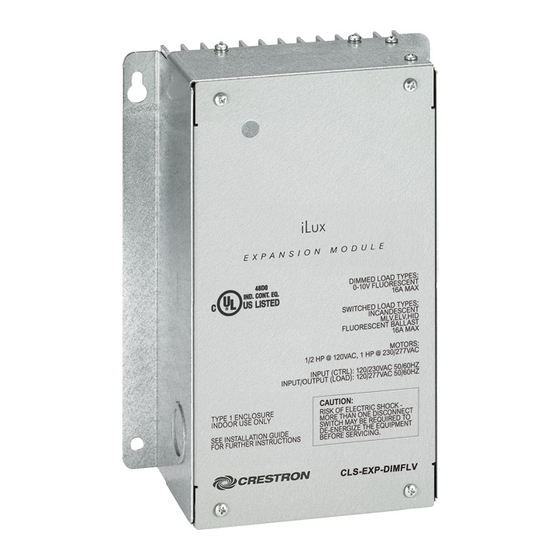
CLS-EXP-DIMFLV
0-10 V Fluorescent Dimmer Expansion Module
Installation Guide
Description
The Crestron
®
CLS-EXP-DIMFLV enables the expansion of iLux
®
Integrated Lighting
System (CLS-C6 Series) and other Crestron lighting dimmers to allow control of 0-10
volt fluorescent dimming ballasts. It can also be used to switch nondimmable loads
including LED, incandescent, MLV, ELV, HID, fluorescent ballasts, and motors. The
CLS-EXP-DIMFLV supports 120, 230, or 277 volt loads up to 16 amps.
Any output channel of the iLux system can be used to control the CLS-EXP-DIMFLV to
dim a fully loaded circuit. It is also compatible with CLW-series in-wall dimmers and select
CLX-series lighting control modules. The metal enclosure is designed for mounting to
a vertical surface and can be installed in an environmental air-handling space above a
suspended ceiling. Conduit knockouts are provided on the bottom and lower sides. All
connections are made via screw terminals behind the front cover.
NOTE: CLX-series lighting control modules are compatible only with forward-phase
dimming modules.
CLS-EXP-DIMFLV Specifications
Specification
Details
Load Ratings
Dimmer Channels
1
Lamp Load Rating
16 Amps @ 120 to 277 Volts;
Motor Load Rating
0.5 HP @ 120 Volts, 1 HP @ 230/277 Volts
Minimum Load
at 120 volts
15 watts
at 230 volts
25 watts
at 277 volts
30 watts
Load Types
Dimmable Load
0-10 Volt fluorescent ballast or LED driver (4-wire)
Switch Load
LED, incandescent, fluorescent, magnetic low voltage,
electronic low voltage, neon/cold cathode, high-intensity
discharge (HID), motors
Input Voltages
Line Power
120–277 Vac, 50/60 Hz
Control Input
120–230 Vac, 50/60 Hz, phase independent of line power
and load;
Presents a 25 watt load to the controlling device
Electrical Terminals
Captive screw type;
Accommodates two 22–12 AWG (0.34–4.0 mm
wires
Enclosure
Surface mount module with (2) integral mounting
flanges, galvanized steel with gray matte powder
coat front panel, extruded aluminum heat sink,
(4) 1/2 in (13 mm) and 3/4 in (20 mm) conduit
knockouts provided on bottom and lower left and
right sides
Environmental
Temperature
32° to 104 °F (0° to 40 °C)
Humidity
10% to 90% RH (noncondensing)
Heat Dissipation
70 Btu/h at maximum load, 16 amps
Dimensions
Height
8.82 in (224 mm)
Width
6.39 in (163 mm)
Depth
3.18 in (81 mm)
Weight
3.3 lbs (1.5 kg)
5
Maximum Expansion Modules per
Controller Output
Additional Resources
Visit the product page on the Crestron website (www.crestron.com)
for additional information and the latest firmware updates. Use a QR
reader application on your mobile device to scan the QR image.
Physical Description
This section provides information on the connections and indicators available on the
CLS-EXP-DIMFLV.
CLS-EXP-DIMFLV Overall Dimensions - Front View
5.79 in
(148 mm)
4.99 in
Ø 0.19 in
(127 mm)
(5 mm)
(212 mm)
8.82 in
7.31 in
(224 mm)
(186 mm)
)
2
Ø 0.25 in
0.50 in
(7 mm)
(13 mm)
CLS-EXP-DIMFLV Overall Dimensions - Side View
3.18 in
(81 mm)
3.07 in
(78 mm)
1.56 in
(40 mm)
2.02 in
(53 mm)
CLS-EXP-DIMFLV Overall Dimensions - Rear View
6.39 in
(163 mm)
1.64 in
(42 mm)
CLS-EXP-DIMFLV Hardware Connections
INPUT
CTRL: Control input from CLS(I)-C6 Series,
CLW-DIM Series, CLX(I)-DIM Series, GLX-DIM6,
GLXX-2DIM8, DIN-1DIM4, or DIN1-DIMU4
dimmers
NEUT: Neutral connection for control input
8.31 in
OUTPUT
SW OUT: Switched load output
HOT: Line power input
NEUT: Neutral connection for line power input and
load
0-10V
+/-:
(2) Captive screw terminals,1 dimming control
output;
Class 1 or Class 2 wiring allowed;
Control voltage: 0-10 Vdc, 70 mA
Ground
(1) 3-terminal chassis ground bus
bar
Installation
Refer to the following diagram when installing a CLS-EXP-DIMFLV module.
NOTE: Install in accordance with all local and national electrical codes.
NOTE: To prevent potential heat damage to the drywall, do not mount the
CLS-EXP-DIMFLV directly onto drywall. Mount a piece of 1/2 in (13 mm) minimum thick
plywood between the CLS-EXP-DIMFLV and the drywall.
NOTE: To ensure proper ventilation, the device must be installed vertically on a vertical
surface. Install the device with 6 inches (153 mm) of clearance from the top and bottom
of the device.
Module Installation
1.64 in
(42 mm)
CLS-EXP-DIMFLV
#8 mounting screw
(not included)
Mounting surface
Advertisement
Table of Contents

Summary of Contents for Crestron CLS-EXP-DIMFLV
- Page 1 CLS-EXP-DIMFLV supports 120, 230, or 277 volt loads up to 16 amps. plywood between the CLS-EXP-DIMFLV and the drywall. Any output channel of the iLux system can be used to control the CLS-EXP-DIMFLV to NOTE: To ensure proper ventilation, the device must be installed vertically on a vertical dim a fully loaded circuit.
- Page 2 NOTE: This equipment has been tested and found to comply with the limits for a Class B digital device, • Consult the dealer or an experienced radio/TV technician for help. names or their products. Crestron disclaims any proprietary interest in the marks and names of others. Laboratories Inc.


Need help?
Do you have a question about the CLS-EXP-DIMFLV and is the answer not in the manual?
Questions and answers