
Related Manuals for Enterasys WS-AP3765i


Summary of Contents for Enterasys WS-AP3765i
- Page 1 Enterasys Wireless ® Outdoor Access Points Installation Guide WS-AP3765i WS-AP3765e WS-AP3767e P/N 9034664-01...
- Page 3 Enterasys Networks reserves the right to make changes in specifications and other information contained in this document and its web site without prior notice. The reader should in all cases consult Enterasys Networks to determine whether any such changes have been made.
- Page 4 (2) copies of the Licensed Software in whole or in part, including the original media, in your possession for said purposes without Enterasys’ prior written consent, and in no event shall You operate more than one copy of the Licensed Software.
- Page 5 Enterasys in good faith determines that the media and proof of payment of the license fee are returned to Enterasys or the dealer from whom it was obtained within ninety (90) days of the date of payment of the license fee.
- Page 6 (g) Enterasys’ waiver of any right shall not constitute waiver of that right in future. This Agreement constitutes the entire understanding between the parties with respect to the subject matter hereof, and all prior agreements, representations, statements and undertakings, oral or written, are hereby expressly superseded and canceled.
-
Page 7: Table Of Contents
Contents About This Guide Who Should Use This Guide ..........................ix What Is in This Guide ............................ix Related Documents ............................ix Formatting Conventions .............................x Getting Help ................................x Safety Information .............................xi Removing the Housing Cover ........................xi Qualified Personnel .............................xi Prescribed Usage ............................xi Biological Compatibility ..........................xii Disclaimer of Liability .......................... - Page 8 FCC ................................5-5 RSS-210 of Industry Canada .......................... 5-6 Bahrain Notice ..............................5-6 List of Figures Enterasys Wireless Outdoor WS-AP3765 and WS-AP3767e Access Points........1-2 WS-AP3765 LEDs ..........................1-4 WS-AP3767e LEDs ..........................1-5 Reset Button, With The Housing Cover Removed ................1-6 Removing the Housing Cover......................
- Page 9 2-10 Mounting Plate with Fittings for DIN Rail Mounting ................2-10 2-11 Mounting Plate with Fittings for Mast Mounting ................2-11 2-12 Fitting the AP to a Mounting Bracket ....................2-12 2-13 Screwing WS-AP3765 or WS-AP3767e to a Mounting Plate ............2-13 Position of the Opening in the Housing for the Power Supply with the Housing Cover Removed ..
- Page 10 viii...
-
Page 11: About This Guide
WS-AP3765i, WS-AP3765e, and WS-AP3767e access points. In addition, this guide provides information on the product certifications and national approvals for these access points. The WS-AP3765 is available in two versions: — one with internal antennas only (WS-AP3765i), and one with support for external antennas (WS-AP3765e). Each WS-AP3765 model provides one RJ-45 Ethernet port for LAN cable connections. -
Page 12: Formatting Conventions
Elektrischer Gefahrenhinweis: Warnung vor sämtlichen Handlungen, die zu Verletzung von Personen oder Todesfällen – hervorgerufen durch elektrische Spannung – führen können! Getting Help For additional support related to the product or this document, contact Enterasys Networks using one of the following methods: World Wide Web www.enterasys.com/support Phone 1-800-872-8440 (toll-free in U.S. -
Page 13: Safety Information
A description of any action(s) already taken to resolve the problem (for example, changing mode switches or rebooting the unit) • The serial and revision numbers of all involved Enterasys Networks products in the network • A description of your network environment (such as layout, cable type, other relevant environmental information) •... -
Page 14: Biological Compatibility
You will find further information on this topic under the following URL: www.bitkom.org Disclaimer of Liability Enterasys Networks has reviewed the contents of this publication to ensure consistency with the hardware and software described. Since variance cannot be precluded entirely, Enterasys Networks cannot guarantee full consistency. -
Page 15: Chapter 1: Introduction
Introduction This chapter introduces the WS-AP3765i, WS-AP3765e, and WS-AP3767e outdoor access points. For information about... Refer to page... Product Overview Package Contents Accessories and Transceivers Access Point LEDs Reset Button Product Overview The Enterasys Wireless Outdoor WS-AP3765i, WS-AP3765e, and WS-AP3767e access points enable you to extend your Wireless LAN beyond the boundaries of indoor locations. -
Page 16: Package Contents
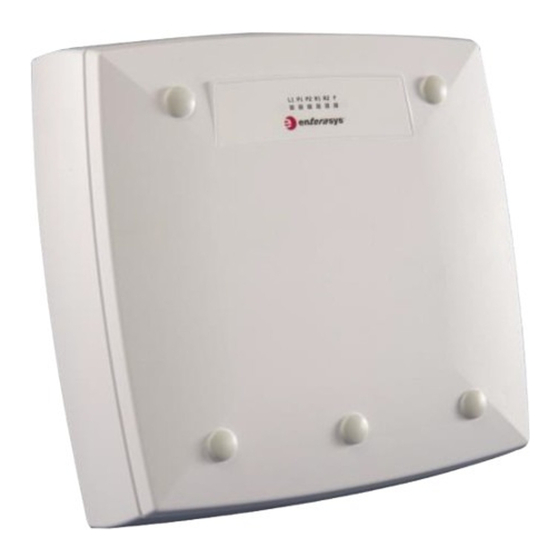
Package Contents Figure 1-1 Enterasys Wireless Outdoor WS-AP3765 and WS-AP3767e Access Points Note: These access points require configuration and control from the Enterasys Wireless Controller. Warning: The WS-AP3765 and WS-AP3767e access points must not be installed in an explosive atmosphere. -
Page 17: Accessories And Transceivers
WS-CAB-LPM Table 1-2 lists the industrial pluggable transceivers that can be used with the WS-AP3767e. These transceivers can be ordered from Enterasys Networks. Supported transceiver models are also listed in the data sheet at: http://www.enterasys .com/products/transceivers-ds.pdf Table 1-2 Pluggable Transceivers Supported for the WS-AP3767e... -
Page 18: Ws-Ap3767E Leds
When off, indicates normal operation, AP connected to controller. WS-AP3767e LEDs The WS-AP3767e frontal view of the housing cover displays six LEDs. These LEDs provide information on operating status. For more information, see the Enterasys Wireless Convergence Software User Guide. 1-4 Introduction... -
Page 19: Reset Button
Warning: Turn off the power supply of the access point before you remove the housing cover. After you have removed the housing cover, turn the power on to use the reset button. Enterasys Wireless Outdoor Access Points Installation Guide 1-5... -
Page 20: Reset Button, With The Housing Cover Removed
Reset Button Figure 1-4 Reset Button, With The Housing Cover Removed The reset button resets the access point to its factory defaults. Press the button quickly to restart the device. Press and hold the button to reset the device to its factory defaults. 1-6 Introduction... -
Page 21: Chapter 2: Mounting The Outdoor Access Point
Only authorized personnel is permitted to open the device and carry out any work on the open device (for example, connection and disconnection of lines, operating the reset button). Enterasys Wireless Outdoor Access Points Installation Guide 2-1... -
Page 22: Attaching Cables
Attaching Cables Figure 2-1 Removing the Housing Cover P o E • A – Sealing cap • B – Cover screw • C – Housing case To remove the housing cover: Remove the sealing caps from the housing cover (Position A in Figure 2-1) Loosen the screws in the cover (Position B in... -
Page 23: Grounding Terminal
Place the supplied toothed washer directly on the rear of the device before screwing on the ground cable. This ensures that there is maximum contact with the screwed-on cable. Enterasys Wireless Outdoor Access Points Installation Guide 2-3... -
Page 24: Mounting Without A Mount Bracket (Wall Mounting Only)
Mounting Without a Mount Bracket (Wall Mounting Only) Figure 2-3 Chassis Ground Connector on Rear of AP Mounting Without a Mount Bracket (Wall Mounting Only) Regarding Installation Location • Devices with an internal antenna must be aligned according to the characteristics of the internal antenna (refer to the technical specifications of the antenna “External Antennas”... -
Page 25: Drilling Template
To mount the access point without a mounting bracket (wall mounting only): Lead the cables into the housing of the access point (Position A in Figure 2-5). Figure 2-5 WS-AP3765 and WS-AP3767e Wall Mounting Enterasys Wireless Outdoor Access Points Installation Guide 2-5... -
Page 26: Mounting With Mounting Bracket
Mounting with Mounting Bracket Secure the AP to the wall with three screws (Position B Figure 2-5). The screws are not supplied with the device. The type and length of the screws depend on the type of wall. Option: Threaded Holes on Rear of Housing When a wall is extremely thin, it is often not possible to use wall plugs for the screws. -
Page 27: Fitting The Mounting Plate To A Wall
Secure the mounting plate to the wall with four screws. Screws are not supplied with the AP. The type and length of the screws depend on the type of wall. Figure 2-7 Fitting the Mounting Plate to a Wall Enterasys Wireless Outdoor Access Points Installation Guide 2-7... -
Page 28: Attaching The Cover Plate To The Mounting Plate
Mounting with Mounting Bracket Attaching the Cover Plate to the Mounting Plate The cabling of the WS-AP3765 and WS-AP3767e is led out of the rear of the device. The housing seal is effective only when it is not subjected to spray water. If the device is mounted on a wall, no further measures are necessary. -
Page 29: Fitting The Mounting Plate To An S7-300 Standard Rail
At the bottom, the mounting plate has two lugs with holes. Screw the lugs to the S7 standard rail (position B in Figure 2-9). The required screws are supplied with the mounting plate. Enterasys Wireless Outdoor Access Points Installation Guide 2-9... -
Page 30: Fitting The Mounting Plate To A Din Rail
Mounting with Mounting Bracket Fitting the Mounting Plate to a DIN Rail To fit the mounting plate to a DIN rail: Place the mounting plate with the two catches (Position A in Figure 2-10) on the upper edge of the DIN rail. Figure 2-10 Mounting Plate with Fittings for DIN Rail Mounting Pull down the DIN rail sliding catch (Position B in... -
Page 31: Fitting The Mounting Plate To A Mast
2-11) to the side to adapt a fastening strap to the diameter of the mast. Press the tensioning screw against the fastening strap and tighten the tensioning screw, tightening torque 4.5 Nm. Enterasys Wireless Outdoor Access Points Installation Guide 2-11... -
Page 32: Fitting The Ap To A Mounting Bracket
Mounting with Mounting Bracket Fitting the AP to a Mounting Bracket To fit an WS-AP3765 or WS-AP3767e to a mounting bracket: Lead the cables into the housing of the AP (Position A in Figure 2-12). For more information, Chapter Connecting Cables to the Outdoor Access Points. -
Page 33: Screwing Ws-Ap3765 Or Ws-Ap3767E To A Mounting Plate
2-12) and release the AP from the recesses. Pull out the lower edge of the AP to the front and then release it from the two clips on the mounting plate (position B in Figure 2-12 on page 2-12). Enterasys Wireless Outdoor Access Points Installation Guide 2-13... - Page 34 Mounting with Mounting Bracket 2-14 Mounting the Outdoor Access Point...
-
Page 35: Chapter 3: Connecting Cables To The Outdoor Access Points
• WARNING: SUBSTITUTION OF COMPONENTS MAY IMPAIR SUITABILITY FOR DIVISION 2. • WARNING: DO NOT DISCONNECT EQUIPMENT WHEN A FLAMMABLE OR COMBUSTIBLE ATMOSPHERE IS PRESENT. Enterasys Wireless Outdoor Access Points Installation Guide 3-1... -
Page 36: Notes On Lightning Protection
Safety Notices Notes on Lightning Protection Warning: Antennas installed outdoors must be within the area covered by a lightning protection system. Make sure that all conducting systems entering from outdoors can be protected by a lightning protection potential equalization system.When implementing your lightning protection concept, make sure you adhere to the VDE 0182 or IEC 62305 standard. -
Page 37: Power/Cables
Ethernet circuits must fulfill SELV requirements and shall be entirely contained within a single low-voltage power distribution and within a single building. • Do not connect any external LAN-circuit, power supply, or antenna coming from outdoors. Enterasys Wireless Outdoor Access Points Installation Guide 3-3... -
Page 38: Hazardous Areas (Ul-Hazloc)
WS-AP3765 / WS-AP3767e Cables and Connectors Hazardous Areas (UL-Hazloc) Warning: Notices cULus haz.loc This equipment is suitable for use in Class I, Division 2, Groups A, B, C, D; Class I, Zone 2, Group IIC or non-hazardous locations. WARNING - Explosion Hazard – Do not disconnect while circuit is live unless area is known to be non-hazardous. -
Page 39: Antenna Connectors
The WS-AP3765e and WS-AP3767e do not have built-in lightning protectors. Additional parts (pigtail connectors) are needed to connect Reverse Type N antennas to the R-SMA AP ports. Table 3-2 is a list of available parts that can be ordered from Enterasys: Table 3-2 Reverse Type N Antenna Connector Parts Part Number... -
Page 40: Pluggable Transceivers
• 24V DC direct voltage Use the two-pin connector supplied with the WS-AP3765 / WS-AP3767e. • 100 - 240V AC alternating voltage Requires the optional power supply adapter WS-PS376X-MR, ordered from Enterasys. 3-6 Connecting Cables to the Outdoor Access Points... -
Page 41: Fitting A Power Supply Adapter
Fitting a Power Supply Adapter The WS-AP3765 / WS-AP3767e supports the 100-240V AC power supply adapter (WS-PS376X-MR) only. This adapter is necessary only for connecting a 100-240V AC power supply to the WS-AP3765 or WS-AP3767e. Enterasys Wireless Outdoor Access Points Installation Guide 3-7... -
Page 42: Using A Power Supply Adapter
Connecting the Cables Note: The Enterasys 100-240V AC power supply adapter (WS-PS376X-MR) is identical to the Siemens PS791-2AC power supply adapter, and is shipped with that part number on the label. Warning: Power supply cables may be connected only when the power is turned off. Start up the AP only after screwing the housing cover in place again so that protection from touching live parts is restored. -
Page 43: Connecting An Ethernet Cable To The Ws-Ap3765
Warning: SFP transceivers may be connected only when the power is turned off. Start up the AP only after screwing the housing cover in place again so that protection from touching live parts is restored. Enterasys Wireless Outdoor Access Points Installation Guide 3-9... -
Page 44: Position Of Sfp Ports With Housing Cover Removed
Connecting the Cables Figure 3-5 Position of SFP Ports with Housing Cover Removed Warning: Fiber-optic SFPs use Class 1 lasers. Do not use optical instruments to view the laser output. The use of optical instruments to view laser output increases eye hazard. When viewing the output optical port, power must be removed from the network adapter. -
Page 45: Connecting Fiber-Optic Cables To An Sfp Port
To connect an external antenna cable to the access point: Insert the connector on the antenna cable into the R-SMA socket and tighten the sleeve nut on the socket (key size SW8), tightening torque 0.6 Nm. Enterasys Wireless Outdoor Access Points Installation Guide 3-11... -
Page 46: Using Strain Relief Clamps On Cable Connections
The Antenna “A1” and “B1” connectors are mapped to the Left antenna and the Antenna “A2” and “B2” connectors are mapped to the Middle antenna on the user interface of the Enterasys Wireless Controller. The “A3” and “B3” connectors are mapped to the Right antenna. -
Page 47: Connecting A Cable And Fitting The Strain Relief Clamps
Figure 3-8 Securing a Sealing Plug with a Strain Relief Clamp Note: Keep unused sealing plugs and strain relief clamps for later use. Enterasys Wireless Outdoor Access Points Installation Guide 3-13... - Page 48 Connecting the Cables 3-14 Connecting Cables to the Outdoor Access Points...
-
Page 49: Chapter 4: Technical Specifications
Internal Antenna Radiation Patterns Antenna Channel Power Settings Outdoor Access Point Technical Specifications This section provides the technical specifications for the WS-AP3765i, WS-AP3765e, and WS- AP3767e outdoor access points. Unless otherwise noted, the specifications for all three models are the same. -
Page 50: Interfaces
36V DC, max. 57V DC via RJ-45 jack, electrically isolated according to IEEE802.3at, dielectric resistance > 2 Mohm • 100 - 240V AC with optional power supply adapter Data • WS-AP3765i RJ-45 jack for Ethernet 6 internal antennas • WS-AP3765e... -
Page 51: Permitted Ambient Conditions
AC 100 ... 240 V, 45 ... 65 Hz Rated current 170 mA ... 70 mA Efficiency, typical 82.2 % Power supply buffering > 20 ms Output voltage DC 18 V Output current 0.8 A Enterasys Wireless Outdoor Access Points Installation Guide 4-3... -
Page 52: External Antennas
External Antennas Table 4-8 lists the certified external antennas for AP3765e and WS-AP3767e. For more detailed specifications and radiation pattern diagrams, see the Enterasys Wireless External Antenna Site Preparation and Installation Guide. Table 4-8 Certified External Antennas for WS-AP3765e and WS-AP3767e... -
Page 53: Internal Antenna Radiation Patterns
Internal Antenna Radiation Patterns Internal Antenna Radiation Patterns The following radiation patterns apply to the antennas in the AP3765i only. Horizontal Radiation Pattern 2500 MHz -150 -120 Vertical Radiation Pattern 2500 MHz -150 -120 Enterasys Wireless Outdoor Access Points Installation Guide 4-5... -
Page 54: Horizontal Radiation Pattern 5800 Mhz
Internal Antenna Radiation Patterns Horizontal Radiation Pattern 5800 MHz -150 -120 Vertical Radiation Pattern 5800 MHz -150 -120 4-6 Technical Specifications... -
Page 55: Antenna Channel Power Settings
FCC/IC Power Setting Tables Table 4-9 shows the necessary FCC/IC-required software power settings for each certified antenna, in each 802.11 mode for WS-AP3765i, WS-AP3765e, and WS-AP3767e. Table 4-9 FCC/IC Antenna Channel Power Settings, Modes B, G, GN-HT20, GN-HT40 Antenna #1... - Page 56 Antenna Channel Power Settings Table 4-9 FCC/IC Antenna Channel Power Settings, Modes B, G, GN-HT20, GN-HT40 (continued) Antenna #1 Antenna #2 Antenna #3 Antenna #4 802.11 AP3765i Channel Mode Internal AO-DT05120-1 AO-DS05360 AO-2S10360 AIO-2S18018 12.5 11.5 16.5 14.5 12.5 13.5 16.5 13.5 13.5...
-
Page 57: Fcc/Ic Antenna Channel Power Settings, Modes A, An-Ht20, An-Ht40
SELECT 36-40 44-48 149-153 20** HT40 157-161 20** AUTO 20** SELECT * Must use a cable with a minimum 4.4dB of loss. **must use a cable with a minimum 8.8dB of loss. Enterasys Wireless Outdoor Access Points Installation Guide 4-9... -
Page 58: Etsi Power Setting Tables
Table 4-11 shows the necessary ETSI-required software power settings for each certified antenna, in 802.11 modes B, G, GN-HT20, and GN-HT40 for WS-AP3765i, WS-AP3765e, and WS-AP3767e. Table 4-12 on page 4-13 shows the ETSI-required software power settings for each certified antenna, in 802.11 modes A, AN-HT20 and AN-HT40 for WS-AP3765i, WS-AP3765e, and WS-... - Page 59 Table 4-11 ETSI Antenna Channel Power Settings, Modes B, G, GN-HT20, GN-HT40 (continued) Antenna #2 Antenna #3 Antenna #4 Antenna #5 802.11 AP3765i Antenna #1 Channel Mode Internal AO-DS05360 AO-2S10360 AO-DX13025 AIO-2S18018 AO-DT05120-1 AUTO SELECT GN-HT20 AUTO SELECT Enterasys Wireless Outdoor Access Points Installation Guide 4-11...
- Page 60 Antenna Channel Power Settings Table 4-11 ETSI Antenna Channel Power Settings, Modes B, G, GN-HT20, GN-HT40 (continued) Antenna #2 Antenna #3 Antenna #4 Antenna #5 802.11 AP3765i Antenna #1 Channel Mode Internal AO-DS05360 AO-2S10360 AO-DX13025 AIO-2S18018 AO-DT05120-1 GN-HT40 6-10 7-11 8-12 9-13 AUTO...
-
Page 61: Etsi Antenna Channel Power Settings, Modes A, An-Ht20, An-Ht40
Table 4-12 ETSI Antenna Channel Power Settings, Modes A, AN-HT20, AN-HT40 Antenna #2 Antenna #3 Antenna #4 Antenna #5 Antenna #6 Antenna #1 802.11 AP3765i Channel Mode Internal DT05120-1 DS05360 5S10360 DX13025 5D16060 5D23009 AUTO SELECT Enterasys Wireless Outdoor Access Points Installation Guide 4-13... - Page 62 Antenna Channel Power Settings Table 4-12 ETSI Antenna Channel Power Settings, Modes A, AN-HT20, AN-HT40 (continued) Antenna #2 Antenna #3 Antenna #4 Antenna #5 Antenna #6 Antenna #1 802.11 AP3765i Channel Mode Internal DT05120-1 DS05360 5S10360 DX13025 5D16060 5D23009 HT20 AUTO SELECT 36-40...
-
Page 63: Chapter 5: Certification
Warning: The Enterasys Wireless Outdoor WS-AP3765i is identical to the SCALANCE-W786-2IA- RJ45 model, the Enterasys Wireless Outdoor WS-AP3765e is identical to the SCALANCE-W786-2- RJ45 model, and the Enterasys Wireless Outdoor WS-AP3767e is identical to the SCALANCE W786-2-SFP. The differences are in the software that communicate with an Enterasys Wireless Controller. - Page 64 Devices connected to the system must meet the relevant safety regulations. The EC Declaration of Conformity is available for the responsible authorities according to the above-mentioned EC Directive at the following address: Enterasys Networks Limited Nexus House, Newbury Business Park London Road, Newbury...
- Page 65 The date of signatory is the initial date that the CE mark was affixed in accordance with these directives. Manufacturer Signature Mr. Thomas R. Whissel Full Name Manager, Compliance Engineering Title Andover MA, USA Location November 20, 2012 Date Enterasys Wireless Outdoor Access Points Installation Guide 5-3...
-
Page 66: Hazardous Location Approvals
Hazardous Location Approvals Hazardous Location Approvals Note: The hazardous location approvals in this section apply to the WS-AP3765 only. ATEX (Explosion Protection Directive) Warning: When using SIMATIC NET products in hazardous area zone 2, make absolutely sure that the associated conditions are adhered to. “Use of subassemblies/modules in a Zone 2 Hazardous Area”. -
Page 67: Culus Approval For Information Technology Equipment
This device must accept any interference received, including interference that may cause undesired operation. Note: Changes or modifications made to this equipment not expressly approved by Enterasys, Inc. may void the FCC authorization to operate this equipment. IEEE802.11b or g operation of this product in the USA is firmware-limited to channels 1 through This equipment has been tested and found to comply with the limits for a Class B digital device, pursuant to Part 15 of the FCC Rules. -
Page 68: Rss-210 Of Industry Canada
RSS-210 of Industry Canada Professional Installation Notice: To comply with FCC part 15 rules in the United States, the system must be professionally installed to ensure compliance with the Part 15 certification. It is the responsibility of the operator and professional installer to ensure that only certified systems are deployed in the United States.
Need help?
Do you have a question about the WS-AP3765i and is the answer not in the manual?
Questions and answers