Table of Contents
Advertisement
Quick Links
Download this manual
See also:
Installation Manual
Installing the WS-AP3710
Electrical Hazard: Only qualified personnel should perform
installation procedures.
For complete installation instructions and safety warnings
about the WS-AP3710, see the Enterasys Wireless AP3710
Installation Guide at
https://extranet.enterasys.com/downloads.
The WS-AP3710 Access Point is the mid-range of the next-
generation Wireless AP37xx product line.
Table 1-1
shows
the specifications of the WS-AP3710 i & e models:
Table 1-1 WS-AP3710i
WS-AP3710e
and
Specifications
Feature
WS-AP3710i
WS-AP3710e
Radios
2
2
LEDs
4
4
1 Ghz Ethernet Port
1
1
Power
<12.9W;
<12.9W;
802.3af
802.3af
Antennas
6 internal single-band
6 external RSMA
antennas
connectors
The WS-AP3710 supports the 802.11n wireless standard,
with full backward compatibility with legacy 802.11a,
802.11g, and 802.11b devices. The WS-AP3710 interoperates
fully with Wireless LANs, including support for VoWLAN,
branch office mode, guest services, RTLS, availability and
mobility features.
Note: The WS-AP3710 is available in an "i" model (with internal
antennas), and an "e" model (with external antennas). Within this
Quick Reference, any reference to WS-AP3710 applies to both
models.
Accessories
Table 2
shows the optional accessories available for the WS-
AP3710:
Table 2 WS-AP3710 Accessories
Accessory
Enterasys Part Number
Drop ceiling T-bar rail mounting
WS-MB3700-1
bracket
Overview
The WS-AP3710 is designed to extend your Wireless LAN
around indoor locations. A mounting bracket is included
for quick and easy mounting of the WS-AP3710 to walls
and drop ceilings.
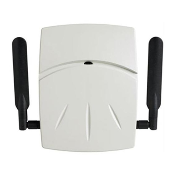
Figure
1, left shows a front view of the
AP3710i and
Figure
1, right shows a front view of the WS-
AP3710e.
Figure 1
Front View of Access Points
1 Reset Switch
5 Kensington Lock Slot
2 LAN Port(s)
6 RSMA Conn. (e models only)
3 Console Port
7 LEDs
4 External Power Supply Port
Table 3
shows the way to power the WS-AP3710:
Table 3 Powering the WS-AP3710
Power
Source
Description
Power
Power is provided through the RJ45 Ethernet port (LAN port)
over
on the top of the WS-AP3710. POE is the preferred method
Ethernet
of powering the AP on ceiling and high wall installations.
(PoE)
Mounting and Connecting the APs
Use these instructions as guidelines for mounting and
connecting the WS-AP3710 easily and safely. More detailed
installation instructions are available in the Enterasys
Wireless AP3710 Installation Guide.
Mounting on a Drop Ceiling
1. Attach the first (3 in
Figure
2) of the two T-bar rail clamps
to the mount bracket. Place the clamp against the top of
the plate so that its two screw holes match up to the
topmost pair of countersink holes, and screw in the
provided screws from underneath the mounting bracket
as shown in
Figure
2. Torque screws to 7.0 in-lbs.
Figure 2
Attaching Rail Clamps To Mount Bracket
Mounting Bracket
5 Top Pair Countersink Holes
1
T-bar Rail Clamp 2
6 Countersink Hole Pair for 9/16" Rail
2
T-bar Rail Clamp 1
7 Countersink Hole Pair for 15/16" Rail
3
Locking Tab
8 Countersink Hole Pair for 1.5" Rail
4
2.
Attach the second T-bar rail clamp to the bracket with
its two screw holes matching up to the pair of
countersink holes at the width needed for the rails you
have, as shown in
Figure
2. Turn the screws into the
mount bracket countersink holes from beneath, no
more than one or two turns so the second clamp is
attached but loose.
3.
Remove the ceiling panels around the drop ceiling T-
bar rails where you intend to mount the AP. Verify that
the Ethernet cable that will connect to the AP can reach
the AP at the point where you plan to mount it.
4.
Hold the bracket and clamp assembly in one hand with
the two clamps spread and held apart by a finger, and
fit the edges of the clamps over the T-bar rail on both
sides of the rail at once. Release the clamps over the rail
and tighten the screws the rest of the way in the
countersink holes (torque screws to 7.0 in-lbs).
5.
Fit the back of the AP against the mounting bracket
with the locking tab aligned with the lock screw hole,
and slide it backward so that the end of the AP is
against the locking tab, as shown in
Figure
3.
Figure 3
Mounting to Drop Ceiling Mount
1 Connector Bay
4 Locking Screw
2 Bracket and Clamp Assembly
5 Locking Tab
3 T-bar Rail
6 Locking Screw Hole
6.
Thread the locking screw (4) into the locking tab and
AP hole to secure the AP in place
(Figure
3). Torque
the screw to 7.0 in-lbs.
Warning: If the screw is not inserted as described in this
step, there is a strong risk the WS-AP3710 could fall from
the bracket.
7.
Make a hole through the ceiling panel closest to the
power slot on the AP. Then run the Ethernet cable
through the hole and into the RJ45 LAN port in the
recessed connector bay.
8.
Replace the displaced ceiling panels.
Mounting on a Wall
1.
Determine the spot on the wall where the AP is to be
mounted, preferably high up on the wall (near the
ceiling for maximum radio wave dispersion) but in
reach of the Ethernet cable.
2.
Place the WS-AP3710 wall mounting bracket firmly
against the wall surface.
3.
Secure the bracket to the wall with three screws (see
Figure
4) through the wall mounting holes.
Figure 4
Mounting the Wall Bracket to a Wall
1 Rail slots
4 Locking Tab
2 Ethernet, Console Cables
5 Locking Screw
3 Mounting Bracket
6 Wall Mounting Holes
4.
Plug the Ethernet cable into the RJ-45 port on the back
of the AP before mounting the AP on the bracket.
5.
Place the back of the AP against the mounting bracket
so that the bracket side rails fit into the rail slots on the
back of the AP and the locking screw hole in the AP
aligns with the locking tab. Slide the AP down until
the AP rests on the locking tab, and screw in the
locking screw through the locking tab and locking
screw hole.
Figure 4
shows what the AP would look
like with the mounting bracket in place.
Warning: If the screw is not inserted as described in this
step, there is a strong risk the WS-AP3710 could fall from
the bracket.
LAN/Console Connections
The WS-AP3710 has both a LAN and a Console port. Refer
to
Figure 1
for the location of these ports. To access these
ports on the WS-AP3710, remove the AP from its mount
on the ceiling or wall first. During administration and
maintenance through the LAN or Console, the AP must
have a power connection through an Ethernet PoE cable.
Advertisement
Table of Contents

Related Manuals for Enterasys WS-AP3710i


Summary of Contents for Enterasys WS-AP3710i
- Page 1 For complete installation instructions and safety warnings bar rails where you intend to mount the AP. Verify that about the WS-AP3710, see the Enterasys Wireless AP3710 the Ethernet cable that will connect to the AP can reach Installation Guide at the AP at the point where you plan to mount it.
- Page 2 ΤΗΣ Ο∆ΗΓΙΑΣ 1999/5/ΕΚ. Qualified Personnel: European Waste Electrical and Electronic Icelandic Enterasys lysir her med yfir að thessi bunadur, Radio LAN Electrical Hazard: Only qualified personnel should perform device, uppfyllir allar grunnkrofur, sem gerdar eru i R&TTE Equipment (WEEE) Notice installation procedures.
Need help?
Do you have a question about the WS-AP3710i and is the answer not in the manual?
Questions and answers