Juniper ACX1000 Hardware Manual
Universal metro router
Hide thumbs
Also See for ACX1000:
- Configuration manual (3270 pages) ,
- User manual (216 pages) ,
- Hardware manual (204 pages)
Table of Contents
Advertisement
Quick Links
Advertisement
Table of Contents
Troubleshooting

Related Manuals for Juniper ACX1000


Summary of Contents for Juniper ACX1000
- Page 1 ACX1000 and ACX1100 Universal Metro Router Hardware Guide Published 2022-12-05...
- Page 2 The Juniper Networks product that is the subject of this technical documentation consists of (or is intended for use with) Juniper Networks software. Use of such software is subject to the terms and conditions of the End User License Agreement ("EULA") posted at https:/ /support.juniper.net/support/eula/.
-
Page 3: Table Of Contents
Uplink Ports on ACX1000 and ACX1100 Routers | 51 LEDs on ACX1000 and ACX1100 Routers | 55 Cooling System and Airflow in an ACX1000 and ACX1100 Router | 58 ACX1000 and ACX1100 Power System | 60 ACX1000 and ACX1100 Power Overview | 60... - Page 4 Console or Auxiliary Port Connector Pinout on ACX Series Routers | 89 USB Port Specifications for an ACX Series Router | 90 External Clocking Ports Specifications on the ACX1000 and ACX1100 Router | 91 Initial Installation and Configuration Installing and Connecting an ACX1000 or ACX1100 Router Overview | 93...
- Page 5 Connecting the Router to a Network for Out-of-Band Management | 107 Connecting the Router to a Management Console or Auxiliary Device | 108 Connecting the ACX1000 or ACX1100 Router to an External Alarm-Reporting Device | 109 Connecting the ACX1000 or ACX1100 Router to External Clocking Devices | 110...
- Page 6 Contacting Customer Support and Returning the Chassis or Components Contacting Customer Support and Returning the Chassis or Components | 136 How to Return a Hardware Component to Juniper Networks, Inc. | 136 Displaying ACX1000 and ACX1100 Components and Serial Numbers | 137...
- Page 7 Agency Approvals for ACX1000 and ACX1100 Routers | 179 Compliance Statements for NEBS for ACX1000 and ACX1100 Routers | 182 Compliance Statements for EMC Requirements for ACX1000 and ACX1100 Routers | 182 Compliance Statements for Environmental Requirements | 184 Compliance Statements for Acoustic Noise for ACX1000 and ACX1100 Routers | 184...
-
Page 8: About This Guide
Use this guide to install hardware and perform initial software configuration, routine maintenance, and troubleshooting for the ACX1000 and ACX1100 Universal Metro router. After completing the installation and basic configuration procedures covered in this guide, refer to the Junos OS documentation for information about further software configuration. -
Page 9: Overview
C HAPTER Overview ACX1000 and ACX1100 System Overview | 2 ACX1000 and ACX1100 Chassis Components | 45 Cooling System and Airflow in an ACX1000 and ACX1100 Router | 58 ACX1000 and ACX1100 Power System | 60... -
Page 10: Acx1000 And Acx1100 System Overview
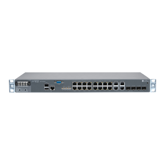
ACX1000 Router Description | 3 ACX1100 Router Description | 4 The ACX1000 and ACX1100 Universal Metro Routers are principally designed to provide superior management for rapid provisioning to the access network. The ACX Series routers support rich Gigabit Ethernet and 10-Gigabit Ethernet capabilities for uplink, along with support for legacy interfaces and Gigabit Ethernet interfaces in a compact form factor that is environmentally hardened and passively cooled. - Page 11 ACX1000 Router Description The ACX1000 routers contain eight T1/E1 ports and twelve Gigabit Ethernet ports, eight of which are RJ-45 ports. The ports labeled COMBO PORTS provide an additional four RJ-45 ports or four Gigabit Ethernet SFP ports. You can use only one set of combination ports at a time.
- Page 12 Figure 1 on page 4 Figure 2 on page 4 show the front and rear views of the ACX1000 router. Figure 1: Front View of the ACX1000 Router Figure 2: Rear View of the ACX1000 Router ACX1100 Router Description The ACX1100 routers contain twelve Gigabit Ethernet ports, eight of which are RJ-45 ports. The ports labeled COMBO PORTS provide an additional four RJ-45 ports or four Gigabit Ethernet SFP ports.
-
Page 13: Acx1000 And Acx1100 Routers Hardware And Cli Terminology Mapping
LEDs on ACX1000 and ACX1100 Routers | 55 ACX1000 and ACX1100 Routers Hardware and CLI Terminology Mapping IN THIS SECTION ACX1000 and ACX1100 Routers Hardware and CLI Terminology Mapping | 6 ACX1100 Routers Hardware and CLI Terminology Mapping | 8... - Page 14 Junos OS command line interface (CLI). Figure 5 on page 7 shows the port locations of the interfaces. Table 1: CLI Equivalents of Terms Used in Documentation for ACX1000 Router Hardware Description (as Value (as...
- Page 15 (Continued) Table 1: CLI Equivalents of Terms Used in Documentation for ACX1000 Router Hardware Description (as Value (as Item in Documentation Additional Information Item (as displayed in the displayed in the displayed in CLI) CLI) the CLI) One of the...
- Page 16 CLI) the CLI) Chassis ACX1100 – Router chassis "Chassis Physical Specifications for ACX1000 and ACX1100 Routers" on page 71 n is FPC ( Abbreviated name Value of The router does not Interface Naming of the Flexible PIC always 0.
- Page 17 AC or DC power supply "ACX1000 and supply ( supply always 0. ACX1100 Power Overview" on page 60 – "Cooling System and Airflow in an ACX1000 NOTE: ACX1100 and ACX1100 Router" routers are fanless on page 58 models. Figure 6: ACX1100 Interface Port Mapping...
-
Page 18: Packet Flow On Acx Series Routers
Packet Flow on ACX Series Routers The class-of-service (CoS) architecture for ACX Series routers is in concept similar to that for MX Series routers. The general architecture for ACX Series routers is shown in Figure 7 on page Figure 7: ACX Series Router Packet Forwarding and Data Flow Based on the model, ACX Series routers contain a built-in Routing Engine and Packet Forwarding Engine and can contain both T1/E1 and Gigabit Ethernet Ports. -
Page 19: Protocols And Applications Supported By Acx Series Routers
The packet pipeline through an ACX Series router is shown in Figure 8 on page 11. Note that the rate limiting is done with an integrated architecture along with all other CoS functions. Scheduling and shaping are supported on the output side. Figure 8: ACX Series Router Packet Handling SEE ALSO ACX2000 and ACX2100 Routers Hardware and CLI Terminology Mapping... - Page 20 MTU values are not limited to 1500 but can range between 256 to 9216. For more information, see the Knowledge Base (KB) article KB28179 at: https:/ / kb.juniper.net/InfoCenter/index?page=content&id=KB28179. Table 3: Protocols and Applications Supported by ACX Series Routers Protocol or Application ACX1...
- Page 21 (Continued) Table 3: Protocols and Applications Supported by ACX Series Routers Protocol or Application ACX1 ACX1 ACX2 ACX2 ACX2 ACX4 ACX5 ACX5 ACX5 ACX5 T1 interfaces 12.2 – 12.2 12.2R – – – – – – Circuit emulation 12.2 – 12.2 12.2R 12.3x...
- Page 22 (Continued) Table 3: Protocols and Applications Supported by ACX Series Routers Protocol or Application ACX1 ACX1 ACX2 ACX2 ACX2 ACX4 ACX5 ACX5 ACX5 ACX5 OSPF 12.2 12.2R 12.2 12.2R 12.3X 12.3x 15.1X 15.1X 12.3X 18.2R –D15 -D10 –D20 –D20 –D20 (Indoo 12.3X –D25...
- Page 23 (Continued) Table 3: Protocols and Applications Supported by ACX Series Routers Protocol or Application ACX1 ACX1 ACX2 ACX2 ACX2 ACX4 ACX5 ACX5 ACX5 ACX5 Internet Control 12.2 12.2R 12.2 12.2R 12.3X 12.3x 15.1X 15.1X 12.3X 18.2R Message Protocol (ICMP) –D15 -D10 –D20 –D20...
- Page 24 (Continued) Table 3: Protocols and Applications Supported by ACX Series Routers Protocol or Application ACX1 ACX1 ACX2 ACX2 ACX2 ACX4 ACX5 ACX5 ACX5 ACX5 Dynamic Host 12.2 12.2R 12.2 12.2R 12.3X 12.3x 15.1X 15.1X 12.3X 18.2R Configuration Protocol (DHCP) –D15 -D10 –D20 –D20...
- Page 25 (Continued) Table 3: Protocols and Applications Supported by ACX Series Routers Protocol or Application ACX1 ACX1 ACX2 ACX2 ACX2 ACX4 ACX5 ACX5 ACX5 ACX5 Layer 3 VPNs 12.3R 12.3R 12.3R 12.3R 12.3X 12.3x 15.1X 15.1X 12.3X 18.2R –D15 -D10 –D20 –D20 –D20 (Indoo...
- Page 26 (Continued) Table 3: Protocols and Applications Supported by ACX Series Routers Protocol or Application ACX1 ACX1 ACX2 ACX2 ACX2 ACX4 ACX5 ACX5 ACX5 ACX5 Static label-switched 12.2 12.2R 12.2 12.2R 12.3X 12.3x 15.1X 15.1X 12.3X 18.2R path (LSP) –D15 -D10 –D20 –D20 –D20...
- Page 27 (Continued) Table 3: Protocols and Applications Supported by ACX Series Routers Protocol or Application ACX1 ACX1 ACX2 ACX2 ACX2 ACX4 ACX5 ACX5 ACX5 ACX5 E-LINE 12.2 12.2R 12.2 12.2R 12.3X 12.3x 15.1X 15.1X 12.3X 18.2R –D15 -D10 –D20 –D20 –D20 (Indoo 12.3X –D25...
- Page 28 (Continued) Table 3: Protocols and Applications Supported by ACX Series Routers Protocol or Application ACX1 ACX1 ACX2 ACX2 ACX2 ACX4 ACX5 ACX5 ACX5 ACX5 IEE802.1ag CC 12.2 12.2R 12.2 12.2R 12.3X 12.3x 15.1X 15.1X 12.3X 18.2R monitoring on active and standby –D15 -D10 –D20...
- Page 29 (Continued) Table 3: Protocols and Applications Supported by ACX Series Routers Protocol or Application ACX1 ACX1 ACX2 ACX2 ACX2 ACX4 ACX5 ACX5 ACX5 ACX5 802.1ag connectivity 12.2 12.2R 12.2 12.2R 12.3X 12.3x 15.1X 15.1X 12.3X 18.2R fault management (CFM) –D15 -D10 –D20 –D20...
- Page 30 (Continued) Table 3: Protocols and Applications Supported by ACX Series Routers Protocol or Application ACX1 ACX1 ACX2 ACX2 ACX2 ACX4 ACX5 ACX5 ACX5 ACX5 Standard firewall filter 12.2 12.2R 12.2 12.2R 12.3X 12.3x 15.1X 15.1X 12.3X 18.2R match conditions for MPLS traffic –D15 -D10...
- Page 31 (Continued) Table 3: Protocols and Applications Supported by ACX Series Routers Protocol or Application ACX1 ACX1 ACX2 ACX2 ACX2 ACX4 ACX5 ACX5 ACX5 ACX5 Policing—per physical 12.2 12.2R 12.2 12.2R 12.3X 12.3x 15.1X 15.1X 12.3X 18.2R interface –D15 -D10 –D20 –D20 –D20 (Indoo...
- Page 32 (Continued) Table 3: Protocols and Applications Supported by ACX Series Routers Protocol or Application ACX1 ACX1 ACX2 ACX2 ACX2 ACX4 ACX5 ACX5 ACX5 ACX5 SrTCM (color aware, 12.2 12.2R 12.2 12.2R 12.3X 12.3x 15.1X 15.1X 12.3X 18.2R color blind) –D15 -D10 –D20 –D20...
- Page 33 (Continued) Table 3: Protocols and Applications Supported by ACX Series Routers Protocol or Application ACX1 ACX1 ACX2 ACX2 ACX2 ACX4 ACX5 ACX5 ACX5 ACX5 Priority queuing 12.2 12.2R 12.2 12.2R 12.3X 12.3x 15.1X 15.1X 12.3X 18.2R –D15 -D10 –D20 –D20 –D20 (Indoo 12.3X...
- Page 34 (Continued) Table 3: Protocols and Applications Supported by ACX Series Routers Protocol or Application ACX1 ACX1 ACX2 ACX2 ACX2 ACX4 ACX5 ACX5 ACX5 ACX5 Low-latency queue 12.2 12.2R 12.2 12.2R 12.3X 12.3x 15.1X 15.1X 12.3X 18.2R (LLQ) –D15 -D10 –D20 –D20 –D20 (Indoo...
- Page 35 (Continued) Table 3: Protocols and Applications Supported by ACX Series Routers Protocol or Application ACX1 ACX1 ACX2 ACX2 ACX2 ACX4 ACX5 ACX5 ACX5 ACX5 Classification—MPLS 12.2 12.2R 12.2 12.2R 12.3X 12.3x 15.1X 15.1X 12.3X 18.2R –D15 -D10 –D20 –D20 –D20 (Indoo 12.3X –D25...
- Page 36 (Continued) Table 3: Protocols and Applications Supported by ACX Series Routers Protocol or Application ACX1 ACX1 ACX2 ACX2 ACX2 ACX4 ACX5 ACX5 ACX5 ACX5 Rewrite MPLS EXP 12.2 12.2R 12.2 12.2R 12.3X 12.3x 15.1X 15.1X 12.3X 18.2R –D15 -D10 –D20 –D20 –D20 (Indoo...
- Page 37 (Continued) Table 3: Protocols and Applications Supported by ACX Series Routers Protocol or Application ACX1 ACX1 ACX2 ACX2 ACX2 ACX4 ACX5 ACX5 ACX5 ACX5 Timing-1588-v2, 12.2 12.2R 12.2 12.2R 12.3X 12.3x – – 12.3X 18.2R 1588-2008–backup clock –D15 -D10 –D20 (Indoo 12.3X –D25...
- Page 38 (Continued) Table 3: Protocols and Applications Supported by ACX Series Routers Protocol or Application ACX1 ACX1 ACX2 ACX2 ACX2 ACX4 ACX5 ACX5 ACX5 ACX5 Clock synchronization 12.2 12.2R 12.2 12.2R 12.3X 12.3x – – 12.3X –D15 -D10 –D20 (Indoo 12.3X –D25 (Outd oor)
- Page 39 (Continued) Table 3: Protocols and Applications Supported by ACX Series Routers Protocol or Application ACX1 ACX1 ACX2 ACX2 ACX2 ACX4 ACX5 ACX5 ACX5 ACX5 Network Time Protocol 12.2 12.2R 12.2 12.2R 12.3X 12.3x 15.1X 15.1X 12.3X 18.2R (NTP) –D15 -D10 –D20 –D20 –D20...
- Page 40 (Continued) Table 3: Protocols and Applications Supported by ACX Series Routers Protocol or Application ACX1 ACX1 ACX2 ACX2 ACX2 ACX4 ACX5 ACX5 ACX5 ACX5 802.3ah LFM 12.2 12.2R 12.2 12.2R 12.3X 12.3x 15.1X 15.1X 12.3X 18.2R –D15 -D10 –D20 –D20 –D20 (Indoo 12.3X...
- Page 41 (Continued) Table 3: Protocols and Applications Supported by ACX Series Routers Protocol or Application ACX1 ACX1 ACX2 ACX2 ACX2 ACX4 ACX5 ACX5 ACX5 ACX5 RMON 12.2 12.2R 12.2 12.2R 12.3X 12.3x 15.1X 15.1X 12.3X 18.2R –D15 -D10 –D20 –D20 –D20 (Indoo 12.3X –D25...
- Page 42 (Continued) Table 3: Protocols and Applications Supported by ACX Series Routers Protocol or Application ACX1 ACX1 ACX2 ACX2 ACX2 ACX4 ACX5 ACX5 ACX5 ACX5 TFTP for software 12.2 12.2R 12.2 12.2R 12.3X 12.3x 15.1X 15.1X 12.3X 18.2R downloads –D15 -D10 –D20 –D20 –D20...
- Page 43 (Continued) Table 3: Protocols and Applications Supported by ACX Series Routers Protocol or Application ACX1 ACX1 ACX2 ACX2 ACX2 ACX4 ACX5 ACX5 ACX5 ACX5 Ethernet loopback 12.2 12.2R 12.2 12.2R 12.3X 12.3x – – 12.3X –D15 -D10 –D20 (Indoo 12.3X –D25 (Outd oor)
- Page 44 (Continued) Table 3: Protocols and Applications Supported by ACX Series Routers Protocol or Application ACX1 ACX1 ACX2 ACX2 ACX2 ACX4 ACX5 ACX5 ACX5 ACX5 Drop packet stats 12.2 12.2R 12.2 12.2R 12.3X 12.3x 15.1X 15.1X 12.3X 18.2R –D15 -D10 –D20 –D20 –D20 (Indoo...
- Page 45 (Continued) Table 3: Protocols and Applications Supported by ACX Series Routers Protocol or Application ACX1 ACX1 ACX2 ACX2 ACX2 ACX4 ACX5 ACX5 ACX5 ACX5 Multipacket mirror – – – – – – – – 12.3X –D20 (Indoo 12.3X –D25 (Outd oor) Security TACACS AAA...
- Page 46 (Continued) Table 3: Protocols and Applications Supported by ACX Series Routers Protocol or Application ACX1 ACX1 ACX2 ACX2 ACX2 ACX4 ACX5 ACX5 ACX5 ACX5 Control plane DOS 12.2 12.2R 12.2 12.2R 12.3X 12.3x 15.1X 15.1X 12.3X 18.2R prevention –D15 -D10 –D20 –D20 –D20...
- Page 47 (Continued) Table 3: Protocols and Applications Supported by ACX Series Routers Protocol or Application ACX1 ACX1 ACX2 ACX2 ACX2 ACX4 ACX5 ACX5 ACX5 ACX5 ATM over PWE3 12.2 – 12.2 12.2R 12.3X 12.3x – – – –D15 -D10 RFC4717 ATM 12.2 12.2R 12.2...
- Page 48 (Continued) Table 3: Protocols and Applications Supported by ACX Series Routers Protocol or Application ACX1 ACX1 ACX2 ACX2 ACX2 ACX4 ACX5 ACX5 ACX5 ACX5 ATM PWE3 by means of 12.2 12.2R 12.2 12.2R 12.3X 12.3x – – 12.3X dynamic labels –D15 -D10 –D20...
- Page 49 (Continued) Table 3: Protocols and Applications Supported by ACX Series Routers Protocol or Application ACX1 ACX1 ACX2 ACX2 ACX2 ACX4 ACX5 ACX5 ACX5 ACX5 ATM support for N to 1 12.2 12.2R 12.2 12.2R 12.3X 12.3x – – 12.3X PW promiscuous mode: 1 PW per port and 1 PW –D15 -D10...
- Page 50 (Continued) Table 3: Protocols and Applications Supported by ACX Series Routers Protocol or Application ACX1 ACX1 ACX2 ACX2 ACX2 ACX4 ACX5 ACX5 ACX5 ACX5 Inverse multiplexing 12.2 12.2R 12.2 12.2R 12.3X 12.3x – – 12.3X over ATM (IMA) –D15 -D10 –D20 (Indoo 12.3X...
- Page 51 (Continued) Table 3: Protocols and Applications Supported by ACX Series Routers Protocol or Application ACX1 ACX1 ACX2 ACX2 ACX2 ACX4 ACX5 ACX5 ACX5 ACX5 MAP ATM service 12.2 12.2R 12.2 12.2R 12.3X 12.3x – – 12.3X categories to PW EXP bits –D15 -D10...
- Page 52 12.2R 12.2 12.2R 12.3X 12.3x 15.1X 15.1X 12.3X 18.2R –D15 -D10 –D20 –D20 –D20 (Indoo 12.3X –D25 (Outd oor) Juniper Networks 12.2 12.2R 12.2 12.2R 12.3X 12.3x 15.1X 15.1X 12.3X 18.2R enterprise-specific MIBs –D15 -D10 –D20 –D20 –D20 (Indoo 12.3X –D25...
-
Page 53: Acx1000 And Acx1100 Chassis Components
The external alarm contact has 15 pins that accept a single core wire from external alarm devices. A DE15 alarm cable is required to connect the ACX1000 and ACX1100 router to external alarm devices. Use the gauge wire appropriate for the external device that you are connecting. - Page 54 Table 4: Alarm Relay Contact Functions Contact Name Contact Name Function Contact 1 Normally Open (NO) Current is not flowing through Contact 1 and Contact 2 [REF] when operating normally. When the current flows, the closed alarm is generated. Normally Closed Current is flowing through Contact 1 and Contact 2 [REF] when (NC) operating normally.
-
Page 55: Clocking Ports On The Acx1000 And Acx1100 Router
Figure 10: Sample Input Alarm-Reporting Device SEE ALSO Alarm Contact Port Pinouts for ACX1000 and ACX1100 Routers | 86 Clocking Ports on the ACX1000 and ACX1100 Router The clocking ports acquire the clock source and synchronize communication over time-division multiplexing (TDM) interfaces in the router. -
Page 56: Front Panel Of An Acx1000 Router
External Clocking Ports Specifications on the ACX1000 and ACX1100 Router | 91 Connecting the ACX1000 or ACX1100 Router to External Clocking Devices | 110 Front Panel of an ACX1000 Router The front panel of an ACX1000 router consists of the following components (see Figure 11 on page 49): •... -
Page 57: Front Panel Of An Acx1100 Router
• Combination Gigabit Ethernet ports labeled 0/2/0 through 0/2/3, either: • Four Gigabit Ethernet RJ-45 ports labeled Cu • Four Gigabit Ethernet ports labeled SFP that accept SFP transceivers Figure 11: Front Panel of the ACX1000 Router DC terminals ESD point —... - Page 58 • AC power inlets or DC power terminals • USB port for upgrading Junos OS • Management Ethernet port labeled MGMT • Console or auxiliary port labeled CONSOLE/AUX • Alarm contact port labeled ALARM—accepts a DE-15 alarm cable • External clocking input port labeled EXT REF CLK IN •...
-
Page 59: Uplink Ports On Acx1000 And Acx1100 Routers
— — SEE ALSO ACX1000 and ACX1100 Universal Metro Router Overview | 2 ACX1000 and ACX1100 Routers Hardware and CLI Terminology Mapping | 5 Uplink Ports on ACX1000 and ACX1100 Routers IN THIS SECTION T1/E1 Ports | 52 Gigabit Ethernet RJ-45 Ports | 53... - Page 60 Unless otherwise specified, the information about uplink ports applies to both ACX1000 and ACX1100 routers. TIP: You can find information about the pluggable transceivers supported on your Juniper Networks device by using the Hardware Compatibility Tool. In addition to transceiver and connector type, the optical and cable characteristics—where applicable—are documented for...
- Page 61 E1 framing: through Gigabit Ethernet RJ-45 Ports Each ACX1000 and ACX1100 router has twelve Gigabit Ethernet RJ-45 ports. Table 6 on page 53 describes the ports in more detail. Table 6: RJ-45 Port Features Feature Description Supported standards •...
- Page 62 Supported See the Hardware Compatibility Tool for the specifications of transceivers supported on the standards ACX1000 or ACX1100. The list of supported transceivers for the ACX1000 is located at https:/ /pathfinder.juniper.net/hct/product/#prd=ACX1000. The list of supported transceivers for the ACX1100 is located at https:/ /pathfinder.juniper.net/hct/product/#prd=ACX1100.
-
Page 63: Leds On Acx1000 And Acx1100 Routers
Ethernet Port LEDs | 56 SFP Port LEDs | 57 Management and Console Port LEDs on the Front Panel | 57 Unless otherwise specified, the information about LEDs applies to both ACX1000 and ACX1100 routers. System LED on the Front Panel One bicolor LED labeled SYS indicates the status of the router. - Page 64 Description Router has failed. steadily T1/E1 Port LEDs The front panel of the ACX1000 router has eight T1/E1 ports, each with one pair of port LEDs. Table 9 on page 56 describes the LEDs in more detail. Table 9: T1/E1 Port LEDs...
- Page 65 (Continued) Table 10: Ethernet Port LEDs Name Location Color State Description – No link. Left Green Blinking The port is receiving data. – The port is not receiving data. SFP Port LEDs The front panel has four Gigabit Ethernet SFP ports, each with one pair of port LEDs. Table 11 on page describes the LEDs in more detail.
-
Page 66: Cooling System And Airflow In An Acx1000 And Acx1100 Router
The port is receiving data. – The port is not receiving data. SEE ALSO Troubleshooting Resources for ACX1000 and ACX1100 Routers | 130 Front Panel of an ACX1000 Router | 48 Cooling System and Airflow in an ACX1000 and ACX1100 Router... - Page 67 Temperature sensors in the chassis monitor the temperature within the chassis. If the temperature inside the chassis rises above the threshold, the router shuts down automatically. Figure 14: Cooling System and Airflow in an ACX1000 and ACX1100 Router RELATED DOCUMENTATION...
-
Page 68: Acx1000 And Acx1100 Power System
ACX1000 and ACX1100 DC Power Specifications | 63 ACX1000 and ACX1100 Power Overview Both ACX1000 and ACX1100 routers are available as DC-powered models. The ACX1100 router is also available as an AC-powered model. The power supply in the router is built along the front panel of the chassis, with the DC power terminals or AC inlets on the front to connect power to the router. -
Page 69: Acx1100 Ac Power Specifications
ACX1100 AC Power Specifications Table 14 on page 61 lists the AC power system electrical specifications. Table 14: AC Power System Electrical Specifications Item Specification AC input voltage Operating range: 100 to 240 VAC AC input line frequency 50 to 60 Hz (nominal) AC system current rating 2 A (100 VAC) or 1 A (240 VAC) AC system input power... - Page 70 You can order detachable AC power cords, each approximately 8 ft (2.5 m) long that supply AC power to the router. The C15 appliance coupler end of the cord, as described by International Electrotechnical Commission (IEC) standard 60320, inserts into the AC appliance inlet coupler. The plug end of the power cord fits into the power source receptacle that is standard for your geographic location.
-
Page 71: Acx1000 And Acx1100 Dc Power Specifications
ACX1000 and ACX1100 DC Power Specifications The power supplies in ACX1000 and ACX1100 routers are built in along the front left panel of the chassis with DC power terminals to connect power to the router. The power supplies are labeled PS0 and PS1. - Page 72 36.6 W @-60 V and 0.61 A 37.2 W @-60 V and 0.62 A SEE ALSO ACX1000 and ACX1100 DC Power Electrical Safety Guidelines | 170 DC Power Copper Conductors Warning | 172 DC Power Disconnection Warning | 172 DC Power Grounding Requirements and Warning | 174...
-
Page 73: Site Planning, Preparation, And Specifications
C HAPTER Site Planning, Preparation, and Specifications Site Preparation Checklist for ACX1000 and ACX1100 Routers | 66 ACX1000 and ACX1100 Site Guidelines and Requirements | 68 ACX1000 and ACX1100 Network Cable and Transceiver Planning | 80 ACX1000 and ACX1100 Alarm, Management, and Clocking Cable Specifications... -
Page 74: Site Preparation Checklist For Acx1000 And Acx1100 Routers
Site Preparation Checklist for ACX1000 and ACX1100 Routers The checklist in Table 17 on page 66 summarizes the tasks you need to perform when preparing a site for ACX1000 and ACX1100 router installation. Table 17: Site Preparation Checklist Item or Task... - Page 75 Review the maximum distance allowed for each cable. Choose the length of cable based on the distance between the hardware components being connected. Plan the cable routing and management. RELATED DOCUMENTATION Installing and Connecting an ACX1000 or ACX1100 Router Overview | 93...
-
Page 76: Acx1000 And Acx1100 Site Guidelines And Requirements
General Site Guidelines | 68 Site Electrical Wiring Guidelines | 69 Clearance Requirements for Airflow and Hardware Maintenance on ACX1000 and ACX1100 Routers | 70 Chassis Physical Specifications for ACX1000 and ACX1100 Routers | 71 ACX1000 and ACX1100 Router Environmental Specifications | 71... -
Page 77: Site Electrical Wiring Guidelines
Site Electrical Wiring Guidelines Table 18 on page 69 describes the factors you must consider while planning the electrical wiring at your site. WARNING: You must provide a properly grounded and shielded environment and use electrical surge-suppression devices. Avertissement Vous devez établir un environnement protégé et convenablement mis à la terre et utiliser des dispositifs de parasurtension. -
Page 78: Clearance Requirements For Airflow And Hardware Maintenance On Acx1000 And Acx1100 Routers
• When deploying the router in harsh environments where the router may operate between 131° F (55° C) and 149° F (65° C), allow a 1–rack unit (U) gap above and below the router. • Minimum 1 meter/second airflow in any direction Figure 15: ACX1000 and ACX1100 Chassis Dimensions and Clearance Requirements... -
Page 79: Chassis Physical Specifications For Acx1000 And Acx1100 Routers
General Site Guidelines | 68 Installing and Connecting an ACX1000 or ACX1100 Router Overview | 93 Chassis Physical Specifications for ACX1000 and ACX1100 Routers The ACX1000 and ACX1100 router is a rigid sheet-metal structure that houses the hardware components. Table 19 on page 71 summarizes the physical specifications of the ACX1000 and ACX1100 router. - Page 80 • The site must be as dust-free as possible, because dust can clog air intake vents and filters, reducing the efficiency of the router cooling system. • Maintain ambient airflow for normal router operation. If the airflow is blocked or restricted, or if the intake air is too warm, the router might overheat, leading to the router temperature monitor shutting down the router to protect the hardware components.
-
Page 81: Acx1000 And Acx1100 Router Grounding Specifications
NOTE: Install the router only in restricted areas, such as dedicated equipment rooms and equipment closets, in accordance with Articles 110-16, 110-17, and 110-18 of the National Electrical Code, ANSI/NFPA 70. ACX1000 and ACX1100 Router Grounding Specifications IN THIS SECTION Grounding Points Specifications | 74... - Page 82 The grounding points fit 0.5-inch-long SAE 10-32 screws (American). The grounding points are spaced at 0.625-in. (15.86-mm) centers. You must install the ACX1000 and ACX1100 routers in a restricted-access location and ensure that the chassis is always properly grounded. The routers have a two-hole protective grounding terminal provided on the chassis.
- Page 83 NOTE: All nonconductive surfaces on the router must be removed from all threads and connection points to ensure electrical continuity. Grounding Cable Lug Specifications The grounding cable lug is used to secure the grounding cable to the grounding points on the ACX chassis.
-
Page 84: Cabinet Requirements For Acx1000 And Acx1100 Routers
• Cabinet size • Clearance requirements • Cabinet airflow requirements Table 21 on page 76 provides the cabinet requirements and specifications for the router. Table 21: Cabinet Requirements and Specifications for the ACX1000 and ACX1100 Router Cabinet Requirement Guidelines Cabinet size •... - Page 85 (Continued) Table 21: Cabinet Requirements and Specifications for the ACX1000 and ACX1100 Router Cabinet Requirement Guidelines Cabinet clearance • The outer edges of the mounting brackets extend the width of the chassis to 19 in. (48.3 cm). • The minimum total clearance inside the cabinet is 30 in.
-
Page 86: Rack Requirements For Acx1000 And Acx1100 Routers
SEE ALSO Site Preparation Checklist for ACX1000 and ACX1100 Routers | 66 Installing and Connecting an ACX1000 or ACX1100 Router Overview | 93 Rack Requirements for ACX1000 and ACX1100 Routers You can mount the router on two-post racks or four-post racks. - Page 87 One pair of mounting brackets for mounting the router on two posts of a rack is supplied with each router. For mounting the router on four posts of a rack or cabinet, you can order a four-post rack-mount kit separately. SEE ALSO Installing and Connecting an ACX1000 or ACX1100 Router Overview | 93...
-
Page 88: Acx1000 And Acx1100 Network Cable And Transceiver Planning
Juniper Networks. If you face a problem running a Juniper device that uses third-party optical modules or cables, JTAC may help you diagnose host-related issues if the observed issue is not, in the opinion of JTAC, related to the use of the third-party optical modules or cables. -
Page 89: Calculating Power Budget And Power Margin For Fiber-Optic Cables
ZR or ZR+) can potentially cause thermal damage to or reduce the lifespan of the host equipment. Any damage to the host equipment due to the use of third-party optical modules or cables is the users’ responsibility. Juniper Networks will accept no liability for any damage caused due to such use. -
Page 90: How To Calculate Power Budget For Fiber-Optic Cables
How to Calculate Power Budget for Fiber-Optic Cables To ensure that fiber-optic connections have sufficient power for correct operation, you need to calculate the link's power budget, which is the maximum amount of power it can transmit. When you calculate the power budget, you use a worst-case analysis to provide a margin of error, even though all the parts of an actual system do not operate at the worst-case levels. - Page 91 (Continued) Table 23: Estimated Values for Factors Causing Link Loss Link-Loss Factor Estimated Link-Loss Value Modal and chromatic dispersion Single mode—None Multimode—None, if product of bandwidth and distance is less than 500 MHz- Faulty connector 0.5 dB Splice 0.5 dB Fiber attenuation Single mode—0.5 dB/km Multimode—1 dB/km...
-
Page 92: Fiber-Optic Cable Signal Loss, Attenuation, And Dispersion
In both examples, the calculated power margin is greater than zero, indicating that the link has sufficient power for transmission and does not exceed the maximum receiver input power. Fiber-Optic Cable Signal Loss, Attenuation, and Dispersion IN THIS SECTION Signal Loss in Multimode and Single-Mode Fiber-Optic Cable | 84 Attenuation and Dispersion in Fiber-Optic Cable | 84 Signal Loss in Multimode and Single-Mode Fiber-Optic Cable Multimode fiber is large enough in diameter to allow rays of light to reflect internally (bounce off the... -
Page 93: Acx1000 And Acx1100 Alarm, Management, And Clocking Cable Specifications And Pinouts
Management Port Connector Pinout Information for ACX Series Routers | 88 Console or Auxiliary Port Connector Pinout on ACX Series Routers | 89 USB Port Specifications for an ACX Series Router | 90 External Clocking Ports Specifications on the ACX1000 and ACX1100 Router | 91... -
Page 94: Alarm Contact Port Pinouts For Acx1000 And Acx1100 Routers
Alarm Contact Port Pinouts for ACX1000 and ACX1100 Routers You can independently configure alarm input ports (0 to 3) to operate in Normally Open or Normally Closed mode, and to trigger a red alarm condition or a yellow alarm condition, or to ignore alarm conditions. - Page 95 (Continued) Table 24: Alarm Contact Connector Pinouts Signal Definition Direction CLI Port Mapping Function Number ALARM_IN0_REF Input Input Alarm Port External alarm input 0 (Reference for Pin 1) ALARM_IN1_NO/NC Input Input Alarm Port External alarm input 1 (if voltage on this pin is between 24V to 72V with reference to Pin 2, alarm input 1 is closed)
-
Page 96: Management Port Connector Pinout Information For Acx Series Routers
Front Panel of an ACX1000 Router | 48 LEDs on ACX1000 and ACX1100 Routers | 55 Alarm Contact Port on ACX1000 and ACX1100 Routers | 45 Management Port Connector Pinout Information for ACX Series Routers The management port— labeled MGMT— on an ACX Series router uses an RJ-45 connector to connect to a management device for out-of-band management. -
Page 97: Console Or Auxiliary Port Connector Pinout On Acx Series Routers
(Continued) Table 25: Management Port Connector Pinout Information Description Direction TRD[1]+ In/Out TRD[2]- In/Out TRD[2]+ In/Out TRD[3]- In/Out TRD[3]+ In/Out Console or Auxiliary Port Connector Pinout on ACX Series Routers The port labeled CONSOLE/AUX on the front panel is an asynchronous serial interface that accept an RJ-45 connector. -
Page 98: Usb Port Specifications For An Acx Series Router
Clear to Send Routing Engine USB Port Specifications for an ACX Series Router The following Juniper Networks USB flash drives have been tested and are officially supported for the USB port on all ACX Series routers: • RE-USB-1G-S • RE-USB-2G-S •... -
Page 99: External Clocking Ports Specifications On The Acx1000 And Acx1100 Router
External Clocking Ports Specifications on the ACX1000 and ACX1100 Router The external clocking port on the ACX1000 and ACX1100 router contains four SMB connectors that support 10 MHz GPS and 1 pulse-per-second (PPS) signals. These signals are internally isolated and have surge protection. -
Page 100: Initial Installation And Configuration
C HAPTER Initial Installation and Configuration Installing and Connecting an ACX1000 or ACX1100 Router Overview | 93 Unpacking and Mounting the ACX1000 and ACX1100 Routers | 94 Connecting the ACX1000 and ACX1100 to Power | 99 Connecting the ACX1000 and ACX1100 to External Devices | 107... -
Page 101: Installing And Connecting An Acx1000 Or Acx1100 Router Overview
• "Connecting ACX1000 or ACX1100 Routers to Management Devices" on page 107 • "Connecting the ACX1000 or ACX1100 Router to an External Alarm-Reporting Device" on page • "Connecting the ACX1000 or ACX1100 Router to External Clocking Devices" on page 110 7. -
Page 102: Unpacking And Mounting The Acx1000 And Acx1100 Routers
Installing the ACX1000 or ACX1100 Router in the Rack | 97 Unpacking an ACX1000 or ACX1100 Router The ACX1000 and ACX1100 routers are shipped in a cardboard carton, secured with foam packing material. The carton also contains an accessory box. -
Page 103: Parts Inventory (Packing List) For An Acx1000 And Acx1100 Router
The parts shipped depend on the configuration you order. If any part on the packing list is missing, contact your customer service representative or contact Juniper Customer Care from within the U.S. or Canada by telephone at 1-888-314-5822. For international-dial or direct-dial options in countries without toll-free numbers, see https:/ /www.juniper.net/support/... -
Page 104: Installing The Acx1000 Or Acx1100 Mounting Brackets
(Continued) Table 27: Parts List for an ACX1000 and ACX1100 Router Component Quantity Quick Start installation instructions Juniper Networks Product Warranty End User License Agreement NOTE: You must provide additional mounting screws if needed that are appropriate for your rack or cabinet to mount the chassis on a rack or a cabinet. -
Page 105: Installing The Acx1000 Or Acx1100 Router In The Rack
4. Repeat the procedure for the other bracket. Figure 18: Installing the Mounting Brackets to the Front of the ACX1000 or ACX1100 Router Figure 19: Installing the Mounting Brackets to the Rear of the ACX1000 or ACX1100 Router SEE ALSO... - Page 106 CAUTION: Before front mounting the router in a rack, have a qualified technician verify that the rack is strong enough to support the router's weight (about 7 lb (3.2 kg)) and is adequately supported at the installation site. NOTE: One person must be available to lift the router while another secures it to the rack. CAUTION: If you are mounting multiple units on a rack, mount the heaviest unit at the bottom of the rack, and mount the other units from the bottom of the rack to the top in decreasing order of the weight of the units.
-
Page 107: Connecting The Acx1000 And Acx1100 To Power
Site Preparation Checklist for ACX1000 and ACX1100 Routers | 66 Connecting the ACX1000 and ACX1100 to Power IN THIS SECTION Connecting the ACX1000 or ACX1100 Router to Earth Ground | 100 Connecting DC Power Cables to the ACX1000 or ACX1100 Router | 102... -
Page 108: Connecting The Acx1000 Or Acx1100 Router To Earth Ground
• Grounding cable, minimum 14 AWG (2 mm ) 90° C wire (not provided) You must install the ACX1000 and ACX1100 routers in a restricted-access location and ensure that the chassis is always properly grounded. The routers have a two-hole protective grounding terminal provided on the chassis. - Page 109 9. Dress the grounding cable, and verify that it does not touch or block access to router components, and that it does not drape where people could trip on it. Figure 21: Grounding Points on the ACX1000 and ACX1100 Router Grounding lug SAE 10-32 screws and washers —...
-
Page 110: Connecting Dc Power Cables To The Acx1000 Or Acx1100 Router
Connecting DC Power Cables to the ACX1000 or ACX1100 Router To connect DC power to the router, you need the following tools: • Phillips (+) screwdriver, number 2 • ESD grounding wrist strap • M3 screws and flat washers • DC power source cables, minimum 14 AWG or as required by local code (not provided) •... - Page 111 To install heat-shrink tubing: a. Slide the tubing over the portion of the cable where it is attached to the lug barrel. Ensure that tubing covers the end of the wire and the barrel of the lug attached to it. b.
- Page 112 CAUTION: Ensure that each power cable lug seats flush against the surface of the terminal block as you are tightening the screws. Ensure that each screw is properly threaded into the terminal. Applying installation torque to the screw when improperly threaded may result in damage to the terminal. CAUTION: The maximum torque rating of the terminal screws on the DC power supply is 9 lb-in.
-
Page 113: Connecting Ac Power Cords To The Acx1100 Router
Figure 23: Connecting DC Power to the Router SEE ALSO ACX1000 and ACX1100 Power Overview | 60 Installing and Connecting an ACX1000 or ACX1100 Router Overview | 93 ACX1000 and ACX1100 DC Power Specifications | 63 Connecting AC Power Cords to the ACX1100 Router To connect AC power to the router, you need the following tools: •... - Page 114 NOTE: Each power supply must be connected to a dedicated AC power feed and a dedicated customer site circuit breaker. We recommend that you use a dedicated customer site circuit breaker rated for 2 A (100 VAC) or 1 A (240 VAC), or as required by local code. 5.
-
Page 115: Connecting The Acx1000 And Acx1100 To External Devices
IN THIS SECTION Connecting ACX1000 or ACX1100 Routers to Management Devices | 107 Connecting the ACX1000 or ACX1100 Router to an External Alarm-Reporting Device | 109 Connecting the ACX1000 or ACX1100 Router to External Clocking Devices | 110 Connecting ACX1000 or ACX1100 Routers to Management Devices... -
Page 116: Connecting The Router To A Management Console Or Auxiliary Device
3. Plug the other end of the cable into the network device. Figure 25: Ethernet Cable Connector Figure 26: Ethernet Port Connecting the Router to a Management Console or Auxiliary Device You can connect a console, laptop, modem, or other auxiliary device by connecting a serial cable to the port on the front panel labeled CONSOLE/AUX. -
Page 117: Connecting The Acx1000 Or Acx1100 Router To An External Alarm-Reporting Device
Figure 27: Routing Engine Console and Auxiliary Cable Connector Figure 28: Auxiliary and Console Connections RELATED DOCUMENTATION Installing and Connecting an ACX1000 or ACX1100 Router Overview | 93 General Site Guidelines | 68 Management Port Connector Pinout Information for ACX Series Routers | 88... -
Page 118: Connecting The Acx1000 Or Acx1100 Router To External Clocking Devices
If attaching a reporting device for the other kind of alarm, repeat the procedure. SEE ALSO Alarm Contact Port on ACX1000 and ACX1100 Routers | 45 Alarm Contact Port Pinouts for ACX1000 and ACX1100 Routers | 86 Connecting the ACX1000 or ACX1100 Router to External Clocking Devices... -
Page 119: Connecting 1Pps And 10Mhz Timing Devices To The Router
The ACX1000 and ACX1100 routers support external clock synchronization for Synchronous Ethernet, T1 or E1 line timing sources, and external inputs. Connecting 1PPS and 10MHz Timing Devices to the Router The router has four SMB connectors that support 1PPS and 10MHz timing devices. -
Page 120: Initially Configuring The Acx1000 Or Acx1100 Router
Initially Configuring the ACX1000 or ACX1100 Router The ACX1000 and ACX1100 routers ship with Junos OS preinstalled and ready to be configured when the router is powered on. One 4-GB internal NAND Flash memory device is divided into two partitions (da0s1 and da0s2). - Page 121 • Domain name that the router will use • IP address and prefix length information for the Ethernet interface • IP address of a default router • IP address of a DNS server • Password for the root user This procedure connects the router to the network but does not enable it to forward traffic. For complete information about enabling the router to forward traffic, including examples, see the Junos OS configuration guides.
- Page 122 Set the user account class to super-user. [edit] root@# set system login user user-name class super-user Configure the router’s domain name. [edit] domain-name root@# set system domain-name Configure the IP address and prefix length for the router’s Ethernet interface. [edit] address/prefix-length root@# set interfaces fxp0 unit 0 family inet address 10.
- Page 123 [edit] public-key root@# set system root-authentication ssh-dsa [edit] public-key root@# set system root-authentication ssh-rsa 13. (Optional) Configure the static routes to remote subnets with access to the management port. Access to the management port is limited to the local subnet. To access the management port from a remote subnet, you need to add a static route to that subnet within the routing table.
- Page 124 18. When you have finished configuring the router, exit configuration mode. [edit] root@host# exit root@host> RELATED DOCUMENTATION ACX1000 and ACX1100 Routers Hardware and CLI Terminology Mapping | 5 Protocols and Applications Supported by ACX Series Routers | 11...
-
Page 125: Maintaining Components
C HAPTER Maintaining components Maintaining ACX1000 and ACX1100 Components | 118... -
Page 126: Maintaining Acx1000 And Acx1100 Components
IN THIS SECTION Routine Maintenance Procedures for the ACX1000 and ACX1100 Router | 118 Maintaining Cables That Connect to ACX1000 and ACX1100 Network Ports | 119 Maintaining the ACX1000 and ACX1100 Uplink Ports | 120 Installing an ACX1000 or ACX1100 Transceiver | 121... -
Page 127: Maintaining Cables That Connect To Acx1000 And Acx1100 Network Ports
Maintaining Cables That Connect to ACX1000 and ACX1100 Network Ports IN THIS SECTION Purpose | 119 Action | 119 Purpose For optimum router performance, verify the condition of the cables that connect to the network ports. Action On a regular basis: •... -
Page 128: Maintaining The Acx1000 And Acx1100 Uplink Ports
Use only an approved alcohol-free fiber-optic cable cleaning kit, such as the Opptex Cletop-S Fiber Cleaner. Follow the directions for the cleaning kit you use. SEE ALSO Troubleshooting Resources for ACX1000 and ACX1100 Routers | 130 Replacing an ACX1000 or ACX1100 Fiber-Optic Cable | 124 Maintaining the ACX1000 and ACX1100 Uplink Ports... -
Page 129: Installing An Acx1000 Or Acx1100 Transceiver
PIC 2 Online 4x 1GE(LAN) SFP, RJ45 SEE ALSO ACX1000 and ACX1100 Routers Hardware and CLI Terminology Mapping | 5 Installing an ACX1000 or ACX1100 Transceiver To install a transceiver: 1. Attach an ESD grounding strap to your bare wrist, and connect the other end of the strap to an ESD grounding point. -
Page 130: Replacing An Acx500 Or Acx1100 Console Or Auxiliary Cable
IN THIS SECTION Removing an ACX500 or ACX1100 Console or Auxiliary Cable | 122 Installing an ACX1000 or ACX1100 Console or Auxiliary Cable | 123 Removing an ACX500 or ACX1100 Console or Auxiliary Cable To remove a serial cable connected to a console or auxiliary device: 1. -
Page 131: Installing An Acx1000 Or Acx1100 Console Or Auxiliary Cable
Console or Auxiliary Port Connector Pinout on ACX Series Routers | 89 Replacing an ACX1000 or ACX1100 Management Ethernet Cable IN THIS SECTION Removing an ACX1000 or ACX1100 Management Ethernet Cable | 123 Installing an ACX1000 and ACX1100 Management Ethernet Cable | 124 Removing an ACX1000 or ACX1100 Management Ethernet Cable To remove a serial cable connected to a management device: 1. -
Page 132: Installing An Acx1000 And Acx1100 Management Ethernet Cable
Management Port Connector Pinout Information for ACX Series Routers | 88 Replacing an ACX1000 or ACX1100 Fiber-Optic Cable IN THIS SECTION Disconnecting an ACX1000 or ACX1100 Fiber-Optic Cable | 125 Connecting an ACX1000 or ACX1100 Fiber-Optic Cable | 125 To replace a fiber-optic cable:... -
Page 133: Disconnecting An Acx1000 Or Acx1100 Fiber-Optic Cable
Disconnecting an ACX1000 or ACX1100 Fiber-Optic Cable ACX Series routers have field-replaceable unit (FRU) optical transceivers to which you can connect fiber- optic cables. Before you begin disconnecting a fiber-optic cable from an optical transceiver installed in an ACX Series router, ensure that you have taken the necessary precautions for safe handling of lasers (see "Laser and... - Page 134 ACX Series routers have field-replaceable unit (FRU) optical transceivers to which you can connect fiber- optic cables. To connect a fiber-optic cable to an optical transceiver installed in an ACX Series router: LASER WARNING: Do not look directly into a fiber-optic transceiver or into the ends of fiber-optic cables.
-
Page 135: Replacing An Acx1000 Or Acx1100 Transceiver
Removing an ACX1000 or ACX1100 Transceiver | 127 Small form-factor pluggable transceivers (SFPs) are optical transceivers that are installed in the front panel of the ACX1000 and ACX1100 router. Transceivers are hot-insertable and hot-removable. Removing an ACX1000 or ACX1100 Transceiver Removing a transceiver does not interrupt router functioning, but the removed transceiver no longer receives or transmits data. - Page 136 CAUTION: After removing a transceiver from the chassis, wait at least 30 seconds before reinserting it or inserting a transceiver into a different slot. SEE ALSO Front Panel of an ACX1000 Router | 48 Uplink Ports on ACX1000 and ACX1100 Routers | 51...
-
Page 137: Troubleshooting Hardware
C HAPTER Troubleshooting Hardware Troubleshooting ACX1000 and ACX1100 | 130... -
Page 138: Troubleshooting Acx1000 And Acx1100
Troubleshooting ACX1000 and ACX1100 IN THIS SECTION Troubleshooting Resources for ACX1000 and ACX1100 Routers | 130 Monitoring System Log Messages | 131 Verifying Active Alarms | 131 Alarm Types and Severity Classes on ACX Series Routers | 133 Troubleshooting Resources for ACX1000 and ACX1100 Routers... -
Page 139: Monitoring System Log Messages
• Link LEDs—Each network port has one pair of port LEDs that indicate the status of the ports. For more information on front panel LEDs, see "LEDs on ACX1000 and ACX1100 Routers" on page Monitoring System Log Messages IN THIS SECTION... - Page 140 Action | 132 Meaning | 132 Purpose Use the monitoring functionality to view alarm information for the ACX Series routers, including alarm type, alarm severity, and a brief description for each active alarm on the router. Action • Observe the system LED on the front panel of the router. If the router is functioning normally with no alarms, the system LED lights green steadily.
-
Page 141: Alarm Types And Severity Classes On Acx Series Routers
Table 28: Alarm Output Fields (Continued) Field Values Class Alarm severity—either major or minor. Description Brief synopsis of the alarm. Alarm Types and Severity Classes on ACX Series Routers IN THIS SECTION Alarm Types | 134 Alarm Severity Classes | 134 Before monitoring the alarms on the router, become familiar with the terms defined in Table 29 on page 133. - Page 142 (Continued) Table 29: Alarm Terms Term Definition System alarm Predefined alarm that is triggered by a missing rescue configuration or failure to install a license for a licensed software feature. Alarm Types The router supports these alarms: • Chassis alarms indicate a failure on the router or one of its components. Chassis alarms are preset and cannot be modified.
-
Page 143: Contacting Customer Support And Returning The Chassis Or Components | 136
C HAPTER Contacting Customer Support and Returning the Chassis or Components Contacting Customer Support and Returning the Chassis or Components | 136... -
Page 144: Contacting Customer Support And Returning The Chassis Or Components
NOTE: Do not return any component to Juniper Networks, Inc. unless you have first obtained an RMA number. Juniper Networks, Inc. reserves the right to refuse shipments that do not have an RMA. -
Page 145: Displaying Acx1000 And Acx1100 Components And Serial Numbers
Displaying ACX1000 and ACX1100 Components and Serial Numbers Before contacting Juniper Networks, Inc. to request a Return Materials Authorization (RMA), you must find the serial number on the router or component. To display all of the router components and their serial numbers, enter the following command-line interface (CLI) command: user@host>... -
Page 146: Acx1000 And Acx1100 Chassis Serial Number Label
ACX1000 and ACX1100 Chassis Serial Number Label The chassis serial number is located on the rear of the chassis (see Figure 34 on page 138). Figure 34: ACX1000 Chassis Serial Number Label Guidelines for Packing Hardware Components for Shipment To pack and ship individual components: •... - Page 147 Retrieve the shipping box and packing materials in which the router was originally shipped. If you do not have these materials, contact your Juniper Networks representative about approved packaging materials. On the console or other management device connected to the Routing Engine, enter CLI operational mode and issue the following command to shut down the router software.
-
Page 148: Safety And Compliance Information
Action to Take After an Electrical Accident | 166 Prevention of Electrostatic Discharge Damage | 167 ACX1100 AC Power Electrical Safety Guidelines | 168 AC Power Disconnection Warning | 170 ACX1000 and ACX1100 DC Power Electrical Safety Guidelines | 170... - Page 149 Multiple Power Supplies Disconnection Warning | 178 TN Power Warning | 179 Agency Approvals for ACX1000 and ACX1100 Routers | 179 Compliance Statements for NEBS for ACX1000 and ACX1100 Routers | 182 Compliance Statements for EMC Requirements for ACX1000 and ACX1100 Routers | 182...
-
Page 150: General Safety Guidelines And Warnings
General Safety Guidelines and Warnings The following guidelines help ensure your safety and protect the device from damage. The list of guidelines might not address all potentially hazardous situations in your working environment, so be alert and exercise good judgment at all times. •... -
Page 151: Definitions Of Safety Warning Levels
• Some parts of the chassis, including AC and DC power supply surfaces, power supply unit handles, SFB card handles, and fan tray handles might become hot. The following label provides the warning for hot surfaces on the chassis: • Always ensure that all modules, power supplies, and cover panels are fully inserted and that the installation screws are fully tightened. - Page 152 Waarschuwing Dit waarschuwingssymbool betekent gevaar. U verkeert in een situatie die lichamelijk letsel kan veroorzaken. Voordat u aan enige apparatuur gaat werken, dient u zich bewust te zijn van de bij elektrische schakelingen betrokken risico's en dient u op de hoogte te zijn van standaard maatregelen om ongelukken te voorkomen. Varoitus Tämä...
-
Page 153: Qualified Personnel Warning
Qualified Personnel Warning WARNING: Only trained and qualified personnel should install or replace the device. Waarschuwing Installatie en reparaties mogen uitsluitend door getraind en bevoegd personeel uitgevoerd worden. Varoitus Ainoastaan koulutettu ja pätevä henkilökunta saa asentaa tai vaihtaa tämän laitteen. Avertissement Tout installation ou remplacement de l'appareil doit être réalisé... -
Page 154: Fire Safety Requirements
In addition, you should establish procedures to protect your equipment in the event of a fire emergency. Juniper Networks products should be installed in an environment suitable for electronic equipment. We recommend that fire suppression equipment be available in the event of a fire in the vicinity of the equipment and that all local fire, safety, and electrical codes and ordinances be observed when you install and operate your equipment. -
Page 155: Installation Instructions Warning
NOTE: To keep warranties effective, do not use a dry chemical fire extinguisher to control a fire at or near a Juniper Networks device. If a dry chemical fire extinguisher is used, the unit is no longer eligible for coverage under a service agreement. -
Page 156: Chassis And Component Lifting Guidelines
Chassis and Component Lifting Guidelines • Before moving the device to a site, ensure that the site meets the power, environmental, and clearance requirements. • Before lifting or moving the device, disconnect all external cables and wires. • As when lifting any heavy object, ensure that your legs bear most of the weight rather than your back. - Page 157 Avertissement Cet appareil est à installer dans des zones d'accès réservé. Ces dernières sont des zones auxquelles seul le personnel de service peut accéder en utilisant un outil spécial, un mécanisme de verrouillage et une clé, ou tout autre moyen de sécurité. L'accès aux zones de sécurité...
-
Page 158: Ramp Warning
Ramp Warning WARNING: When installing the device, do not use a ramp inclined at more than 10 degrees. Waarschuwing Gebruik een oprijplaat niet onder een hoek van meer dan 10 graden. Varoitus Älä käytä sellaista kaltevaa pintaa, jonka kaltevuus ylittää 10 astetta. Avertissement Ne pas utiliser une rampe dont l'inclinaison est supérieure à... - Page 159 Les directives ci-dessous sont destinées à assurer la protection du personnel: • Le rack sur lequel est monté le Juniper Networks switch doit être fixé à la structure du bâtiment.
- Page 160 Le seguenti direttive vengono fornite per garantire la sicurezza personale: • Il Juniper Networks switch deve essere installato in un telaio, il quale deve essere fissato alla struttura dell'edificio. • Questa unità deve venire montata sul fondo del supporto, se si tratta dell'unica unità...
- Page 161 Para garantizar su seguridad, proceda según las siguientes instrucciones: • El Juniper Networks switch debe instalarse en un bastidor fijado a la estructura del edificio. • Colocar el equipo en la parte inferior del bastidor, cuando sea la única unidad en el...
-
Page 162: Grounded Equipment Warning
Följande riktlinjer ges för att trygga din säkerhet: • Juniper Networks switch måste installeras i en ställning som är förankrad i byggnadens struktur. • Om denna enhet är den enda enheten på ställningen skall den installeras längst ned på... -
Page 163: Radiation From Open Port Apertures Warning
Avvertenza Questo dispositivo deve sempre disporre di una connessione a massa. Seguire le istruzioni indicate in questa guida per connettere correttamente il dispositivo a massa. Advarsel Denne enheten på jordes skikkelig hele tiden. Følg instruksjonene i denne veiledningen for å jorde enheten. Aviso Este equipamento deverá... -
Page 164: Laser And Led Safety Guidelines And Warnings
Class 1 LED Product Warning | 158 Laser Beam Warning | 158 Juniper Networks devices are equipped with laser transmitters, which are considered a Class 1 Laser Product by the U.S. Food and Drug Administration and are evaluated as a Class 1 Laser Product per IEC/EN 60825-1 requirements. - Page 165 General Laser Safety Guidelines When working around ports that support optical transceivers, observe the following safety guidelines to prevent eye injury: • Do not look into unterminated ports or at fibers that connect to unknown sources. • Do not examine unterminated optical ports with optical instruments. •...
- Page 166 Class 1 LED Product Warning LASER WARNING: Class 1 LED product. Waarschuwing Klasse 1 LED-product. Varoitus Luokan 1 valodiodituote. Avertissement Alarme de produit LED Class I. Warnung Class 1 LED-Produktwarnung. Avvertenza Avvertenza prodotto LED di Classe 1. Advarsel LED-produkt i klasse 1. Aviso Produto de classe 1 com LED.
-
Page 167: Maintenance And Operational Safety Guidelines And Warnings
Aviso Não olhe fixamente para o raio, nem olhe para ele directamente com instrumentos ópticos. ¡Atención! No mirar fijamente el haz ni observarlo directamente con instrumentos ópticos. Varning! Rikta inte blicken in mot strålen och titta inte direkt på den genom optiska instrument. - Page 168 aanbevolen is. Gebruikte batterijen dienen overeenkomstig fabrieksvoorschriften weggeworpen te worden. Varoitus Räjähdyksen vaara, jos akku on vaihdettu väärään akkuun. Käytä vaihtamiseen ainoastaan saman- tai vastaavantyyppistä akkua, joka on valmistajan suosittelema. Hävitä käytetyt akut valmistajan ohjeiden mukaan. Avertissement Danger d'explosion si la pile n'est pas remplacée correctement. Ne la remplacer que par une pile de type semblable ou équivalent, recommandée par le fabricant.
- Page 169 Waarschuwing Alvorens aan apparatuur te werken die met elektrische leidingen is verbonden, sieraden (inclusief ringen, kettingen en horloges) verwijderen. Metalen voorwerpen worden warm wanneer ze met stroom en aarde zijn verbonden, en kunnen ernstige brandwonden veroorzaken of het metalen voorwerp aan de aansluitklemmen lassen.
- Page 170 Varning! Tag av alla smycken (inklusive ringar, halsband och armbandsur) innan du arbetar på utrustning som är kopplad till kraftledningar. Metallobjekt hettas upp när de kopplas ihop med ström och jord och kan förorsaka allvarliga brännskador; metallobjekt kan också sammansvetsas med kontakterna. Lightning Activity Warning WARNING: Do not work on the system or connect or disconnect cables during periods of lightning activity.
- Page 171 6 in. (15.2 cm) of clearance around the ventilation openings. Waarschuwing Om te voorkomen dat welke switch van de Juniper Networks router dan ook oververhit raakt, dient u deze niet te bedienen op een plaats waar de maximale aanbevolen omgevingstemperatuur van 40°...
- Page 172 ¡Atención! Para impedir que un encaminador de la serie Juniper Networks switch se recaliente, no lo haga funcionar en un área en la que se supere la temperatura ambiente máxima recomendada de 40° C. Para impedir la restricción de la entrada de aire, deje un espacio mínimo de 15,2 cm alrededor de las aperturas para ventilación.
-
Page 173: General Electrical Safety Guidelines And Warnings
General Electrical Safety Guidelines and Warnings WARNING: Certain ports on the device are designed for use as intrabuilding (within- GR-1089-CORE ) the-building) interfaces only (Type 2 or Type 4 ports as described in and require isolation from the exposed outside plant (OSP) cabling. To comply with NEBS (Network Equipment-Building System) requirements and protect against lightning must not be surges and commercial power disturbances, the intrabuilding ports... -
Page 174: Action To Take After An Electrical Accident
• Canada—Canadian Electrical Code, Part 1, CSA C22.1. • Suitable for installation in Information Technology Rooms in accordance with Article 645 of the National Electrical Code and NFPA 75. Peut être installé dans des salles de matériel de traitement de l’information conformément à l’article 645 du National Electrical Code et à... -
Page 175: Prevention Of Electrostatic Discharge Damage
Prevention of Electrostatic Discharge Damage Device components that are shipped in antistatic bags are sensitive to damage from static electricity. Some components can be impaired by voltages as low as 30 V. You can easily generate potentially damaging static voltages whenever you handle plastic or foam packing material or if you move components across plastic or carpets. -
Page 176: Acx1100 Ac Power Electrical Safety Guidelines
• When removing or installing a component that is subject to ESD damage, always place it component- side up on an antistatic surface, in an antistatic card rack, or in an antistatic bag (see Figure 35 on page 168). If you are returning a component, place it in an antistatic bag before packing it. Figure 35: Placing a Component into an Antistatic Bag CAUTION: ANSI/TIA/EIA-568 cables such as Category 5e and Category 6 can get electrostatically charged. - Page 177 • Each AC power supply has one AC appliance inlet. Each inlet requires a dedicated AC power feed and a dedicated customer site circuit breaker. We recommend that you use a dedicated circuit breaker rated at 2 A (100 VAC) or 1 A (240 VAC), or as required by local code. WARNING: The router is pluggable type A equipment installed in a restricted-access location.
-
Page 178: Ac Power Disconnection Warning
(CA). Varning! Innan du arbetar med ett chassi eller nära strömförsörjningsenheter skall du för växelströmsenheter dra ur nätsladden. ACX1000 and ACX1100 DC Power Electrical Safety Guidelines The following electrical safety guidelines apply to a DC-powered router:... - Page 179 • A DC-powered router is equipped with a DC terminal block that is rated for the power requirements of a maximally configured router. To supply sufficient power, terminate the DC input wiring on a facility DC source capable of supplying at least 5 A @ –48 VDC per input for each power supply. We recommend that the 48-VDC facility DC source should be equipped with a circuit breaker rated at 5 A @ –48 VDC) minimum, or as required by local code.
-
Page 180: Dc Power Copper Conductors Warning
DC Power Disconnection Warning | 172 DC Power Grounding Requirements and Warning | 174 DC Power Wiring Sequence Warning | 175 DC Power Wiring Terminations Warning | 176 DC Power Copper Conductors Warning WARNING: Use copper conductors only. Waarschuwing Gebruik alleen koperen geleiders. Varoitus Käytä... - Page 181 stroomverbreker die het gelijkstroom circuit bedient, draait de stroomverbreker naar de UIT positie en plakt de schakelaarhendel van de stroomverbreker met plakband in de UIT positie vast. Varoitus Varmista, että tasavirtapiirissä ei ole virtaa ennen seuraavien toimenpiteiden suorittamista. Varmistaaksesi, että virta on KATKAISTU täysin, paikanna tasavirrasta huolehtivassa kojetaulussa sijaitseva suojakytkin, käännä...
-
Page 182: Dc Power Grounding Requirements And Warning
posición de Apagado (OFF), y sujetar con cinta la palanca del interruptor automático en posición de Apagado (OFF). Varning! Innan du utför någon av följande procedurer måste du kontrollera att strömförsörjningen till likströmskretsen är bruten. Kontrollera att all strömförsörjning är BRUTEN genom att slå... -
Page 183: Dc Power Wiring Sequence Warning
Varning! Vid installation av enheten måste jordledningen alltid anslutas först och kopplas bort sist. DC Power Wiring Sequence Warning WARNING: Wire the DC power supply using the appropriate lugs. When connecting power, the proper wiring sequence is ground to ground, +RTN to +RTN, then –48 V to – 48 V. -
Page 184: Dc Power Wiring Terminations Warning
negativo a negativo (da neutro a N). Tenere presente che il filo di massa deve sempre venire collegato per primo e scollegato per ultimo. Advarsel Riktig tilkoples tilkoplingssekvens er jord til jord, +RTN til +RTN, –48 V til – 48 V. Riktig frakoples tilkoplingssekvens er –48 V til – 48 V, +RTN til +RTN, jord til jord. Aviso Ate con alambre la fuente de potencia cc Usando los terminales apropiados en el extremo del cableado. - Page 185 kiinnityskorvat. Tällaisten liitäntöjen tulee olla kooltaan johtimiin sopivia ja niiden tulee puristaa yhteen sekä eristeen että johdinosan. Avertissement Quand des fils torsadés sont nécessaires, utiliser des douilles terminales homologuées telles que celles à circuit fermé ou du type à plage ouverte avec cosses rebroussées.
-
Page 186: Midplane Energy Hazard Warning
Midplane Energy Hazard Warning WARNING: High levels of electrical energy are distributed across the midplane. Be careful not to contact the midplane connectors, or any component connected to the midplane, with any metallic object while servicing components. Multiple Power Supplies Disconnection Warning WARNING: The network device has more than one power supply connection. -
Page 187: Tn Power Warning
¡Atención! El equipo está diseñado para trabajar con sistemas de alimentación tipo TN. Varning! Enheten är konstruerad för användning tillsammans med elkraftssystem av TN- typ. Agency Approvals for ACX1000 and ACX1100 Routers IN THIS SECTION Compliance Statement for Argentina | 181... - Page 188 ACX1000 and ACX1100 routers comply with the following standards: • Safety • CAN/CSA-22.2 No. 60950-1 (2007), Safety of Information Technology Equipment • UL 60950-1 Information Technology Equipment - Safety - Part 1: General Requirements • EN 60950-1 European Norm, Safety of Information Technology Equipment •...
- Page 189 EQUIPO DE USO IDÓNEO. RELATED DOCUMENTATION Compliance Statements for EMC Requirements for ACX1000 and ACX1100 Routers | 182 Compliance Statements for NEBS for ACX1000 and ACX1100 Routers | 182 Compliance Statements for Acoustic Noise for ACX1000 and ACX1100 Routers | 184...
-
Page 190: Compliance Statements For Nebs For Acx1000 And Acx1100 Routers
GR-1089-CORE. RELATED DOCUMENTATION Agency Approvals for ACX1000 and ACX1100 Routers | 179 Compliance Statements for Acoustic Noise for ACX1000 and ACX1100 Routers | 184 Compliance Statements for Environmental Requirements | 184 Compliance Statements for EMC Requirements for ACX1000 and ACX1100 Routers... - Page 191 Canada CAN ICES-3 (A)/NMB-3(A) European Community This is a Class A product. In a domestic environment, this product might cause radio interference in which case the user might be required to take adequate measures. Israel Translation from Hebrew—Warning: This product is Class A. In residential environments, the product might cause radio interference, and in such a situation, the user might be required to take adequate measures.
-
Page 192: Compliance Statements For Environmental Requirements
Agency Approvals for ACX1000 and ACX1100 Routers | 179 Compliance Statements for NEBS for ACX1000 and ACX1100 Routers | 182 Compliance Statements for Acoustic Noise for ACX1000 and ACX1100 Routers | 184 Compliance Statements for Environmental Requirements | 184 Compliance Statements for Environmental Requirements Batteries in this product are not based on mercury, lead, or cadmium substances. - Page 193 RELATED DOCUMENTATION Compliance Statements for NEBS for ACX1000 and ACX1100 Routers | 182 Compliance Statements for EMC Requirements for ACX1000 and ACX1100 Routers | 182 Compliance Statements for Environmental Requirements | 184...
Need help?
Do you have a question about the ACX1000 and is the answer not in the manual?
Questions and answers