Juniper ACX4000 Hardware Manual
Universal metro router
Hide thumbs
Also See for ACX4000:
- Quick start manual (24 pages) ,
- Configuration manual (3270 pages) ,
- User manual (30 pages)
Table of Contents
Advertisement
Quick Links
Advertisement
Table of Contents
Troubleshooting

Related Manuals for Juniper ACX4000


Summary of Contents for Juniper ACX4000
- Page 1 ACX4000 Universal Metro Router Hardware Guide Published 2022-01-27...
- Page 2 The Juniper Networks product that is the subject of this technical documentation consists of (or is intended for use with) Juniper Networks software. Use of such software is subject to the terms and conditions of the End User License Agreement ("EULA") posted at https:/ /support.juniper.net/support/eula/.
-
Page 3: Table Of Contents
Overview ACX4000 System Overview | 2 ACX4000 Universal Metro Router Overview | 2 ACX4000 Routers Hardware and CLI Terminology Mapping | 4 Packet Flow on ACX Series Routers | 7 Protocols and Applications Supported by ACX Series Routers | 8... - Page 4 ACX4000 Site Guidelines and Requirements | 72 General Site Guidelines | 72 Site Electrical Wiring Guidelines | 73 Clearance Requirements for Airflow and Hardware Maintenance on ACX4000 Routers | 74 Chassis Physical Specifications for ACX4000 Routers | 75 ACX4000 Router Environmental Specifications | 76...
- Page 5 Connecting the ACX4000 Router to External Clocking Devices | 110 Connecting 1PPS and 10MHz Timing Devices to the ACX4000 Router | 110 Connecting a T1 or E1 External Clocking Device to the ACX4000 Router | 110 Connecting the ACX4000 Router to an External Alarm-Reporting Device | 111...
- Page 6 Contacting Customer Support Contacting Customer Support and Returning the Chassis or Components | 157 Displaying ACX4000 Components and Serial Numbers | 157 ACX4000 Chassis Serial Number Label | 158 How to Return a Hardware Component to Juniper Networks, Inc. | 159...
- Page 7 Prevention of Electrostatic Discharge Damage | 188 AC Power Electrical Safety Guidelines | 189 AC Power Disconnection Warning | 190 ACX4000 DC Power Electrical Safety Guidelines | 191 DC Power Copper Conductors Warning | 193 DC Power Disconnection Warning | 193...
- Page 8 TN Power Warning | 199 Agency Approvals for ACX4000 Routers | 200 Compliance Statements for NEBS | 202 Compliance Statements for EMC Requirements | 203 Compliance Statements for Environmental Requirements | 204 Compliance Statements for Acoustic Noise for ACX4000 Routers | 205...
-
Page 9: About This Guide
Use this guide to install hardware and perform initial software configuration, routine maintenance, and troubleshooting for the ACX4000 Universal Metro router. After completing the installation and basic configuration procedures covered in this guide, refer to the Junos OS documentation for information about further software configuration. -
Page 10: Overview
C HAPTER Overview ACX4000 System Overview | 2 ACX4000 Chassis | 42 ACX4000 Cooling System | 56 ACX4000 Power System | 58... -
Page 11: Acx4000 System Overview
Benefits of the ACX4000 Router | 2 Chassis Description | 3 The ACX4000 Universal Metro Router is principally designed to provide superior management for rapid provisioning to the access network. The ACX Series routers support rich Gigabit Ethernet and 10-... - Page 12 Junos OS running on both platforms. The ACX4000 routers are 2.5 rack units (U; that is, 4.375 in., or 11.11 cm) tall. Several routers can be stacked in a single floor-to-ceiling rack for increased port density per unit of floor space.
-
Page 13: Acx4000 Routers Hardware And Cli Terminology Mapping
Chassis Physical Specifications for ACX4000 Routers | 75 ACX4000 Routers Hardware and CLI Terminology Mapping Table 1 on page 5 describes the hardware terms used in ACX4000 router documentation and the corresponding terms used in the Junos OS command line interface (CLI). Figure 3 on page 7 shows the port locations of the interfaces. - Page 14 Table 1: CLI Equivalents of Terms Used in Documentation for ACX4000 Routers Hardware Description (as Value (as displayed Item in Documentation Additional Information Item (as displayed in the in the CLI) displayed in CLI) the CLI) Chassis ACX4000 – Router chassis "Chassis Physical...
- Page 15 (Continued) Table 1: CLI Equivalents of Terms Used in Documentation for ACX4000 Routers Hardware Description (as Value (as displayed Item in Documentation Additional Information Item (as displayed in the in the CLI) displayed in CLI) the CLI) 2x 1GE(LAN) SFP...
-
Page 16: Packet Flow On Acx Series Routers
Figure 3: ACX4000 Interface Port Mapping Packet Flow on ACX Series Routers The class-of-service (CoS) architecture for ACX Series routers is in concept similar to that for MX Series routers. The general architecture for ACX Series routers is shown in... -
Page 17: Protocols And Applications Supported By Acx Series Routers
interest are on the inner VLAN tag of a dual-tagged VLAN interface, the classifier can examine either the inner or outer bits. (By default, the classification is done based on the outer VLAN tag.) Eight queues per egress port support scheduling using the weighted deficit round- robin (WDRR) mechanism, a form of round-robin queue servicing. - Page 18 MTU values are not limited to 1500 but can range between 256 to 9216. For more information, see the Knowledge Base (KB) article KB28179 at: https:/ / kb.juniper.net/InfoCenter/index?page=content&id=KB28179. Table 2: Protocols and Applications Supported by ACX Series Routers Protocol or Application ACX1...
- Page 19 (Continued) Table 2: Protocols and Applications Supported by ACX Series Routers Protocol or Application ACX1 ACX1 ACX2 ACX2 ACX2 ACX4 ACX5 ACX5 ACX5 ACX5 E1 interfaces 12.2 – 12.2 12.2R – – – – – – T1 interfaces 12.2 – 12.2 12.2R –...
- Page 20 (Continued) Table 2: Protocols and Applications Supported by ACX Series Routers Protocol or Application ACX1 ACX1 ACX2 ACX2 ACX2 ACX4 ACX5 ACX5 ACX5 ACX5 OSPF 12.2 12.2R 12.2 12.2R 12.3X 12.3x 15.1X 15.1X 12.3X 18.2R –D15 -D10 –D20 –D20 –D20 (Indoo 12.3X –D25...
- Page 21 (Continued) Table 2: Protocols and Applications Supported by ACX Series Routers Protocol or Application ACX1 ACX1 ACX2 ACX2 ACX2 ACX4 ACX5 ACX5 ACX5 ACX5 Internet Control 12.2 12.2R 12.2 12.2R 12.3X 12.3x 15.1X 15.1X 12.3X 18.2R Message Protocol (ICMP) –D15 -D10 –D20 –D20...
- Page 22 (Continued) Table 2: Protocols and Applications Supported by ACX Series Routers Protocol or Application ACX1 ACX1 ACX2 ACX2 ACX2 ACX4 ACX5 ACX5 ACX5 ACX5 Dynamic Host 12.2 12.2R 12.2 12.2R 12.3X 12.3x 15.1X 15.1X 12.3X 18.2R Configuration Protocol (DHCP) –D15 -D10 –D20 –D20...
- Page 23 (Continued) Table 2: Protocols and Applications Supported by ACX Series Routers Protocol or Application ACX1 ACX1 ACX2 ACX2 ACX2 ACX4 ACX5 ACX5 ACX5 ACX5 Layer 3 VPNs 12.3R 12.3R 12.3R 12.3R 12.3X 12.3x 15.1X 15.1X 12.3X 18.2R –D15 -D10 –D20 –D20 –D20 (Indoo...
- Page 24 (Continued) Table 2: Protocols and Applications Supported by ACX Series Routers Protocol or Application ACX1 ACX1 ACX2 ACX2 ACX2 ACX4 ACX5 ACX5 ACX5 ACX5 Static label-switched 12.2 12.2R 12.2 12.2R 12.3X 12.3x 15.1X 15.1X 12.3X 18.2R path (LSP) –D15 -D10 –D20 –D20 –D20...
- Page 25 (Continued) Table 2: Protocols and Applications Supported by ACX Series Routers Protocol or Application ACX1 ACX1 ACX2 ACX2 ACX2 ACX4 ACX5 ACX5 ACX5 ACX5 E-LINE 12.2 12.2R 12.2 12.2R 12.3X 12.3x 15.1X 15.1X 12.3X 18.2R –D15 -D10 –D20 –D20 –D20 (Indoo 12.3X –D25...
- Page 26 (Continued) Table 2: Protocols and Applications Supported by ACX Series Routers Protocol or Application ACX1 ACX1 ACX2 ACX2 ACX2 ACX4 ACX5 ACX5 ACX5 ACX5 IEE802.1ag CC 12.2 12.2R 12.2 12.2R 12.3X 12.3x 15.1X 15.1X 12.3X 18.2R monitoring on active and standby –D15 -D10 –D20...
- Page 27 (Continued) Table 2: Protocols and Applications Supported by ACX Series Routers Protocol or Application ACX1 ACX1 ACX2 ACX2 ACX2 ACX4 ACX5 ACX5 ACX5 ACX5 802.1ag connectivity 12.2 12.2R 12.2 12.2R 12.3X 12.3x 15.1X 15.1X 12.3X 18.2R fault management (CFM) –D15 -D10 –D20 –D20...
- Page 28 (Continued) Table 2: Protocols and Applications Supported by ACX Series Routers Protocol or Application ACX1 ACX1 ACX2 ACX2 ACX2 ACX4 ACX5 ACX5 ACX5 ACX5 Standard firewall filter 12.2 12.2R 12.2 12.2R 12.3X 12.3x 15.1X 15.1X 12.3X 18.2R match conditions for MPLS traffic –D15 -D10...
- Page 29 (Continued) Table 2: Protocols and Applications Supported by ACX Series Routers Protocol or Application ACX1 ACX1 ACX2 ACX2 ACX2 ACX4 ACX5 ACX5 ACX5 ACX5 Policing—per physical 12.2 12.2R 12.2 12.2R 12.3X 12.3x 15.1X 15.1X 12.3X 18.2R interface –D15 -D10 –D20 –D20 –D20 (Indoo...
- Page 30 (Continued) Table 2: Protocols and Applications Supported by ACX Series Routers Protocol or Application ACX1 ACX1 ACX2 ACX2 ACX2 ACX4 ACX5 ACX5 ACX5 ACX5 SrTCM (color aware, 12.2 12.2R 12.2 12.2R 12.3X 12.3x 15.1X 15.1X 12.3X 18.2R color blind) –D15 -D10 –D20 –D20...
- Page 31 (Continued) Table 2: Protocols and Applications Supported by ACX Series Routers Protocol or Application ACX1 ACX1 ACX2 ACX2 ACX2 ACX4 ACX5 ACX5 ACX5 ACX5 Priority queuing 12.2 12.2R 12.2 12.2R 12.3X 12.3x 15.1X 15.1X 12.3X 18.2R –D15 -D10 –D20 –D20 –D20 (Indoo 12.3X...
- Page 32 (Continued) Table 2: Protocols and Applications Supported by ACX Series Routers Protocol or Application ACX1 ACX1 ACX2 ACX2 ACX2 ACX4 ACX5 ACX5 ACX5 ACX5 Low-latency queue 12.2 12.2R 12.2 12.2R 12.3X 12.3x 15.1X 15.1X 12.3X 18.2R (LLQ) –D15 -D10 –D20 –D20 –D20 (Indoo...
- Page 33 (Continued) Table 2: Protocols and Applications Supported by ACX Series Routers Protocol or Application ACX1 ACX1 ACX2 ACX2 ACX2 ACX4 ACX5 ACX5 ACX5 ACX5 Classification—MPLS 12.2 12.2R 12.2 12.2R 12.3X 12.3x 15.1X 15.1X 12.3X 18.2R –D15 -D10 –D20 –D20 –D20 (Indoo 12.3X –D25...
- Page 34 (Continued) Table 2: Protocols and Applications Supported by ACX Series Routers Protocol or Application ACX1 ACX1 ACX2 ACX2 ACX2 ACX4 ACX5 ACX5 ACX5 ACX5 Rewrite MPLS EXP 12.2 12.2R 12.2 12.2R 12.3X 12.3x 15.1X 15.1X 12.3X 18.2R –D15 -D10 –D20 –D20 –D20 (Indoo...
- Page 35 (Continued) Table 2: Protocols and Applications Supported by ACX Series Routers Protocol or Application ACX1 ACX1 ACX2 ACX2 ACX2 ACX4 ACX5 ACX5 ACX5 ACX5 Timing-1588-v2, 12.2 12.2R 12.2 12.2R 12.3X 12.3x – – 12.3X 18.2R 1588-2008–backup clock –D15 -D10 –D20 (Indoo 12.3X –D25...
- Page 36 (Continued) Table 2: Protocols and Applications Supported by ACX Series Routers Protocol or Application ACX1 ACX1 ACX2 ACX2 ACX2 ACX4 ACX5 ACX5 ACX5 ACX5 Clock synchronization 12.2 12.2R 12.2 12.2R 12.3X 12.3x – – 12.3X –D15 -D10 –D20 (Indoo 12.3X –D25 (Outd oor)
- Page 37 (Continued) Table 2: Protocols and Applications Supported by ACX Series Routers Protocol or Application ACX1 ACX1 ACX2 ACX2 ACX2 ACX4 ACX5 ACX5 ACX5 ACX5 Network Time Protocol 12.2 12.2R 12.2 12.2R 12.3X 12.3x 15.1X 15.1X 12.3X 18.2R (NTP) –D15 -D10 –D20 –D20 –D20...
- Page 38 (Continued) Table 2: Protocols and Applications Supported by ACX Series Routers Protocol or Application ACX1 ACX1 ACX2 ACX2 ACX2 ACX4 ACX5 ACX5 ACX5 ACX5 802.3ah LFM 12.2 12.2R 12.2 12.2R 12.3X 12.3x 15.1X 15.1X 12.3X 18.2R –D15 -D10 –D20 –D20 –D20 (Indoo 12.3X...
- Page 39 (Continued) Table 2: Protocols and Applications Supported by ACX Series Routers Protocol or Application ACX1 ACX1 ACX2 ACX2 ACX2 ACX4 ACX5 ACX5 ACX5 ACX5 RMON 12.2 12.2R 12.2 12.2R 12.3X 12.3x 15.1X 15.1X 12.3X 18.2R –D15 -D10 –D20 –D20 –D20 (Indoo 12.3X –D25...
- Page 40 (Continued) Table 2: Protocols and Applications Supported by ACX Series Routers Protocol or Application ACX1 ACX1 ACX2 ACX2 ACX2 ACX4 ACX5 ACX5 ACX5 ACX5 TFTP for software 12.2 12.2R 12.2 12.2R 12.3X 12.3x 15.1X 15.1X 12.3X 18.2R downloads –D15 -D10 –D20 –D20 –D20...
- Page 41 (Continued) Table 2: Protocols and Applications Supported by ACX Series Routers Protocol or Application ACX1 ACX1 ACX2 ACX2 ACX2 ACX4 ACX5 ACX5 ACX5 ACX5 Ethernet loopback 12.2 12.2R 12.2 12.2R 12.3X 12.3x – – 12.3X –D15 -D10 –D20 (Indoo 12.3X –D25 (Outd oor)
- Page 42 (Continued) Table 2: Protocols and Applications Supported by ACX Series Routers Protocol or Application ACX1 ACX1 ACX2 ACX2 ACX2 ACX4 ACX5 ACX5 ACX5 ACX5 Drop packet stats 12.2 12.2R 12.2 12.2R 12.3X 12.3x 15.1X 15.1X 12.3X 18.2R –D15 -D10 –D20 –D20 –D20 (Indoo...
- Page 43 (Continued) Table 2: Protocols and Applications Supported by ACX Series Routers Protocol or Application ACX1 ACX1 ACX2 ACX2 ACX2 ACX4 ACX5 ACX5 ACX5 ACX5 Multipacket mirror – – – – – – – – 12.3X –D20 (Indoo 12.3X –D25 (Outd oor) Security TACACS AAA...
- Page 44 (Continued) Table 2: Protocols and Applications Supported by ACX Series Routers Protocol or Application ACX1 ACX1 ACX2 ACX2 ACX2 ACX4 ACX5 ACX5 ACX5 ACX5 Control plane DOS 12.2 12.2R 12.2 12.2R 12.3X 12.3x 15.1X 15.1X 12.3X 18.2R prevention –D15 -D10 –D20 –D20 –D20...
- Page 45 (Continued) Table 2: Protocols and Applications Supported by ACX Series Routers Protocol or Application ACX1 ACX1 ACX2 ACX2 ACX2 ACX4 ACX5 ACX5 ACX5 ACX5 ATM over PWE3 12.2 – 12.2 12.2R 12.3X 12.3x – – – –D15 -D10 RFC4717 ATM 12.2 12.2R 12.2...
- Page 46 (Continued) Table 2: Protocols and Applications Supported by ACX Series Routers Protocol or Application ACX1 ACX1 ACX2 ACX2 ACX2 ACX4 ACX5 ACX5 ACX5 ACX5 ATM PWE3 by means of 12.2 12.2R 12.2 12.2R 12.3X 12.3x – – 12.3X dynamic labels –D15 -D10 –D20...
- Page 47 (Continued) Table 2: Protocols and Applications Supported by ACX Series Routers Protocol or Application ACX1 ACX1 ACX2 ACX2 ACX2 ACX4 ACX5 ACX5 ACX5 ACX5 ATM support for N to 1 12.2 12.2R 12.2 12.2R 12.3X 12.3x – – 12.3X PW promiscuous mode: 1 PW per port and 1 PW –D15 -D10...
- Page 48 (Continued) Table 2: Protocols and Applications Supported by ACX Series Routers Protocol or Application ACX1 ACX1 ACX2 ACX2 ACX2 ACX4 ACX5 ACX5 ACX5 ACX5 Inverse multiplexing 12.2 12.2R 12.2 12.2R 12.3X 12.3x – – 12.3X over ATM (IMA) –D15 -D10 –D20 (Indoo 12.3X...
- Page 49 (Continued) Table 2: Protocols and Applications Supported by ACX Series Routers Protocol or Application ACX1 ACX1 ACX2 ACX2 ACX2 ACX4 ACX5 ACX5 ACX5 ACX5 MAP ATM service 12.2 12.2R 12.2 12.2R 12.3X 12.3x – – 12.3X categories to PW EXP bits –D15 -D10...
- Page 50 12.2R 12.2 12.2R 12.3X 12.3x 15.1X 15.1X 12.3X 18.2R –D15 -D10 –D20 –D20 –D20 (Indoo 12.3X –D25 (Outd oor) Juniper Networks 12.2 12.2R 12.2 12.2R 12.3X 12.3x 15.1X 15.1X 12.3X 18.2R enterprise-specific MIBs –D15 -D10 –D20 –D20 –D20 (Indoo 12.3X –D25...
-
Page 51: Acx4000 Chassis
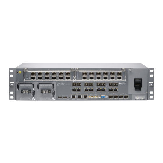
ACX4000 Modular Interface Card (MIC) Overview | 51 ACX4000 LEDs Overview | 52 ACX4000 Front Panel Overview The front panel of an ACX4000 router consists of the following components: • Chassis status LED labeled SYS • Two USB ports for upgrading Junos OS •... - Page 52 • Two Gigabit Ethernet (GE) ports, labeled 0/1/0 and 0/1/1, that accept SFP transceivers • Two 10-Gigabit Ethernet (XE) ports, labeled 0/2/0 and 0/2/1, that accept SFP+ transceivers Figure 6: Front Panel of the ACX4000 Router ESD point Alarm contact ports —...
-
Page 53: Acx4000 Uplink Ports Overview
Gigabit Ethernet Ports | 47 10-Gigabit Ethernet Ports | 47 TIP: You can find information about the pluggable transceivers supported on your Juniper Networks device by using the Hardware Compatibility Tool. In addition to transceiver and connector type, the optical and cable characteristics—where applicable—are documented for each transceiver. - Page 54 Port numbering (hardware) 0/0/0 through 0/0/15 Port numbering (software) ct1-0/0/0 ct1-0/0/15 T1 framing (default): through ce1-0/0/0 ce1-0/0/15 E1 framing: through RJ-45 Ports Each ACX4000 router has six Gigabit Ethernet RJ45 ports. Table 4 on page 46 describes the ports in more detail.
- Page 55 PoE Ports Each ACX4000 router has two PoE Gigabit Ethernet ports. These ports allow you to plug in devices that require both network connectivity and electric power such as IP phones, wireless access points, and security cameras. Table 5 on page 46 describes the ports in more detail.
- Page 56 Table 6: SFP Port Features Feature Description Supported standards See the Hardware Compatibility Tool for the specifications of transceivers supported on the ACX4000. The list of supported transceivers for the ACX4000 is located at https:/ / pathfinder.juniper.net/hct/product/#prd=ACX4000. Cable Connector Port numbering...
-
Page 57: Acx4000 Alarm Contact Port Overview
The external alarm contact has 15 pins that accept a single core wire from external alarm devices. A DE15 alarm cable is required to connect the ACX4000 router to external alarm devices. Use the gauge wire appropriate for the external device that you are connecting. - Page 58 Table 8: Alarm Relay Contact Functions Contact Name Contact Name Function Contact 1 Normally Open (NO) Current is not flowing through Contact 1 and Contact 2 [REF] when operating normally. When the current flows, the closed alarm is generated. Normally Closed Current is flowing through Contact 1 and Contact 2 [REF] when (NC) operating normally.
-
Page 59: Acx4000 Clocking Ports Overview
Figure 8: Sample Input Alarm-Reporting Device SEE ALSO Alarm Contact Port Pinouts for ACX4000 Routers | 87 ACX4000 Clocking Ports Overview The clocking ports acquire the clock source and synchronize communication over time-division multiplexing (TDM) interfaces in the router. The clocking ports distribute a synchronized clock signal throughout the router by locking onto a clock signal originating from an internal clock source or by connecting to an external clock source. -
Page 60: Acx4000 Modular Interface Card (Mic) Overview
ACX4000 Modular Interface Card (MIC) Overview Modular Interface Cards (MICs) install into two slots in the front of the ACX4000 router and provide the physical connections to various network media types. The slots are labeled 1/0 and 1/1. You can install MICs of different media types on the same router as long as the router supports those MICs. -
Page 61: Acx4000 Leds Overview
ACX4000 LEDs Overview IN THIS SECTION System LED on the Front Panel | 52 AC Power Supply LED | 53 DC Power Supply LED | 53 T1/E1 Port LEDs | 54 Ethernet Port LEDs | 54 PoE Port LEDs | 55... - Page 62 AC Power Supply LED One LED labeled AC OK indicates the status of the power supply. Table 10 on page 53 describes the system LED in more detail. Table 10: AC Power LED Label Color State Description AC OK Green Power supply is functioning normally and input voltage is within steadily allowable operating range.
- Page 63 T1/E1 Port LEDs The front panel has sixteen T1/E1 ports, each with one pair of port LEDs. Table 12 on page 54 describes the LEDs in more detail. Table 12: T1/E1 Port LEDs Name Location Color Description Link Left Green Online with no alarms or failures.
- Page 64 PoE Port LEDs The front panel has two PoE Gigabit Ethernet ports, each with one pair of port LEDs. Table 14 on page describes the LEDs in more detail. Table 14: PoE Port LEDs Name Location Color State Description Activity Right Green Blinking...
-
Page 65: Acx4000 Cooling System
LEDs on the MIC faceplate, see the “LEDs” section for each MIC in the ACX4000 Universal Metro Router Interface Module Reference. SEE ALSO Troubleshooting Resources for ACX4000 Routers | 151 ACX4000 Cooling System The cooling system consists of the following components: • Fan tray • Air filter... - Page 66 Figure 9: Cooling System and Airflow in an ACX4000 Router RELATED DOCUMENTATION Rack Requirements for ACX4000 Routers | 80 Cabinet Requirements for ACX4000 Routers | 78 Clearance Requirements for Airflow and Hardware Maintenance on ACX4000 Routers | 74 ACX4000 Router Environmental Specifications | 76...
-
Page 67: Acx4000 Power System
ACX4000 Power Overview IN THIS SECTION AC Power Supplies | 59 DC Power Supplies | 60 The ACX4000 router uses either AC or DC power supplies (see Figure 10 on page 59 Figure 11 on page 60). The power supplies are located in the front of the chassis and offer 1+1 redundancy. The power supply slots are labeled PS 0 and PS 1. - Page 68 configuration with full power for as long as the router is operational. A second power supply can be installed for redundancy. Each power supply is cooled by its own internal cooling system. Redundant power supplies are hot-removable and hot-insertable. When you remove a power supply from a router that uses only one power supply, the router might shut down depending on your configuration.
-
Page 69: Acx4000 Power Consumption
Connecting DC Power Cables to the ACX4000 Router | 104 ACX4000 Power Consumption The power supply in an ACX4000 router is built along the front panel of the chassis, with a DC power terminal on the front to connect power to the router. -
Page 70: Acx4000 Ac Power Specifications
Table 17: Power Consumed by ACX4000 Routers Description Value Maximum consumed by the router 96 W Maximum consumed by the router when no PoE power is drawn 96.6 W Number of PoE ports available Maximum PoE power available 65 W per port... -
Page 71: Acx4000 Ac Power Cord Specifications
ACX4000 AC Power Cord Specifications Each AC power supply has a single AC appliance inlet that requires a dedicated AC power feed. Most sites distribute power through a main conduit that leads to frame-mounted power distribution panels, one of which can be located at the top of the rack that houses the router. - Page 72 (Continued) Table 19: AC Power Cord Specifications Country Model Number Electrical Specification Plug Type Design Standard Europe (except Italy, CBL-GP-C15-EU 250 VAC, 10 A, 50 Hz VIIG CEE (7) VII Switzerland, and United Kingdom) Italy CBL-GP-C15-IT 250 VAC, 10 A, 50 Hz I/3G CEI 23–16 Japan...
-
Page 73: Acx4000 Dc Power Specifications
ACX4000 DC Power Specifications The power supply in ACX4000 routers is built in along the front left panel of the chassis with DC power terminals to connect power to the router. The ACX4000 router supports a wide range of voltage ranges as shown in... -
Page 74: Acx4000 Dc Power Cable And Lug Specifications
SEE ALSO ACX4000 DC Power Electrical Safety Guidelines | 191 DC Power Copper Conductors Warning | 193 DC Power Disconnection Warning | 193... - Page 75 14-AWG (2.08 mm ), minimum 60° C wire, or as required by the local code. SEE ALSO ACX4000 DC Power Electrical Safety Guidelines | 191 DC Power Copper Conductors Warning | 193 DC Power Disconnection Warning | 193 DC Power Grounding Requirements and Warning | 195...
-
Page 76: Acx4000 Router Grounding Specifications
The grounding points fit 0.5-inch-long SAE 10-32 screws (American). The grounding points are spaced at 0.625-in. (15.86-mm) centers. You must install the ACX4000 in a restricted-access location and ensure that the chassis is always properly grounded. The ACX4000 has a two-hole protective grounding terminal provided on the chassis. - Page 77 EMC regulatory requirements with the two- hole protective grounding terminal. Figure 13: Grounding Points on the ACX4000 Routers NOTE: All bare grounding connection points to the router must be cleaned and coated with an antioxidant solution before grounding the router.
- Page 78 You must provide one grounding cable that meets the following specifications: 6-AWG (4.11 mm minimum 90°C wire, or as required by the local code. SEE ALSO Connecting the ACX4000 Router to Earth Ground | 101 Prevention of Electrostatic Discharge Damage | 188...
-
Page 79: Site Planning, Preparation, And Specifications
C HAPTER Site Planning, Preparation, and Specifications Site Preparation Checklist for ACX4000 Routers | 71 ACX4000 Site Guidelines and Requirements | 72 ACX4000 Network Cable and Transceiver Planning | 82 ACX4000 Alarm, Management, and Clocking Cable Specifications and Pinouts |... -
Page 80: Site Preparation Checklist For Acx4000 Routers
Plan the location of the rack, including required space for airflow and maintenance. See "Clearance Requirements for Airflow and Hardware Maintenance on ACX4000 Routers" on page Plan to secure the rack to the floor and building structure. See "Rack Requirements for ACX4000 Routers"... -
Page 81: Acx4000 Site Guidelines And Requirements
IN THIS SECTION General Site Guidelines | 72 Site Electrical Wiring Guidelines | 73 Clearance Requirements for Airflow and Hardware Maintenance on ACX4000 Routers | 74 Chassis Physical Specifications for ACX4000 Routers | 75 ACX4000 Router Environmental Specifications | 76... -
Page 82: Site Electrical Wiring Guidelines
• Follow prescribed airflow guidelines to ensure that the cooling system functions properly and that exhaust from other equipment does not blow into the intake vents of the device. • Follow the prescribed electrostatic discharge (ESD) prevention procedures to prevent damaging the equipment. -
Page 83: Clearance Requirements For Airflow And Hardware Maintenance On Acx4000 Routers
Electrical hazards as a result of power surges conducted over the lines into the equipment Clearance Requirements for Airflow and Hardware Maintenance on ACX4000 Routers When planning the installation site, allow sufficient clearance around the rack (see Figure 15 on page 75): •... -
Page 84: Chassis Physical Specifications For Acx4000 Routers
SEE ALSO Installing and Connecting an ACX4000 Router Overview | 94 Chassis Physical Specifications for ACX4000 Routers The ACX4000 router is a rigid sheet-metal structure that houses the hardware components. Table 22 on page 76 summarizes the physical specifications of the ACX4000 router. -
Page 85: Acx4000 Router Environmental Specifications
Table 22: Physical Specifications of the ACX4000 Router Chassis Description Value Height 4.375 in. (11.11 cm) Width • 17.5 in. (44.5 cm) • 19.2 in. (48.7 cm) with mounting brackets attached Depth 9.5 in. (24.13 cm) Weight 16.98 lb (7.69 kg) - Page 86 Table 23: Router Environmental Specifications Description Value Altitude No performance degradation to 10,000 ft (3048 m) Relative humidity Normal operation ensured in relative humidity range of 5% to 90%, noncondensing Temperature • Harsh environment: –40°F (–40°C) to 149°F (65°C) • Central office environment: 23°F (–5°C) to 131°F (55°C) Commercial grade SFP/SFP+ •...
-
Page 87: Cabinet Requirements For Acx4000 Routers
• Cabinet size • Clearance requirements • Cabinet airflow requirements Table 24 on page 78 provides the cabinet requirements and specifications for the router. Table 24: Cabinet Requirements and Specifications for the ACX4000 Router Cabinet Requirement Guidelines Cabinet size •... - Page 88 (Continued) Table 24: Cabinet Requirements and Specifications for the ACX4000 Router Cabinet Requirement Guidelines Cabinet clearance • The outer edges of the mounting brackets extend the width of the chassis to 19 in. (48.3 cm). • The minimum total clearance inside the cabinet is 30 in.
-
Page 89: Rack Requirements For Acx4000 Routers
SEE ALSO Installing and Connecting an ACX4000 Router Overview | 94 Rack Requirements for ACX4000 Routers You can mount the router on two-post racks or four-post racks. Rack requirements consist of: • Rack type • Mounting bracket hole spacing • Rack size and strength •... - Page 90 One pair of mounting brackets for mounting the router on two posts of a rack is supplied with each router. For mounting the router on four posts of a rack or cabinet, you can order a four-post rack-mount kit separately. SEE ALSO Installing and Connecting an ACX4000 Router Overview | 94...
-
Page 91: Acx4000 Network Cable And Transceiver Planning
See the Junos OS documentation for your device for a description of the monitoring fields. CAUTION: If you face a problem running a Juniper Networks device that uses a third- party optic or cable, the Juniper Networks Technical Assistance Center (JTAC) can help you diagnose the source of the problem. -
Page 92: Calculating Power Budget And Power Margin For Fiber-Optic Cables
TIP: You can use the Hardware Compatibility Tool to find information about the pluggable transceivers supported on your Juniper Networks device. To calculate the power budget and power margin, perform the following tasks: How to Calculate Power Budget for Fiber-Optic Cables To ensure that fiber-optic connections have sufficient power for correct operation, you need to calculate the link's power budget, which is the maximum amount of power it can transmit. -
Page 93: How To Calculate Power Margin For Fiber-Optic Cables
How to Calculate Power Margin for Fiber-Optic Cables After calculating a link's power budget, you can calculate the power margin (P ), which represents the amount of power available after subtracting attenuation or link loss (LL) from the power budget (P ). -
Page 94: Fiber-Optic Cable Signal Loss, Attenuation, And Dispersion
= 13 dB – 2 km (1 dB/km) – 5 (0.5 dB) – 2 (0.5 dB) – 0.5 dB = 13 dB – 2 dB – 2.5 dB – 1 dB – 0.5 dB = 7 dB The following sample calculation for an 8-km-long single-mode link with a power budget (P ) of 13 dB uses the estimated values from Table 26 on page... - Page 95 Single-mode fiber is so small in diameter that rays of light can reflect internally through one layer only. Interfaces with single-mode optics use lasers as light sources. Lasers generate a single wavelength of light, which travels in a straight line through the single-mode fiber. Compared with multimode fiber, single-mode fiber has higher bandwidth and can carry signals for longer distances.
-
Page 96: Acx4000 Alarm, Management, And Clocking Cable Specifications And Pinouts
ACX4000 Alarm, Management, and Clocking Cable Specifications and Pinouts IN THIS SECTION Alarm Contact Port Pinouts for ACX4000 Routers | 87 Management Port Connector Pinout Information for ACX Series Routers | 89 Console or Auxiliary Port Connector Pinout on ACX Series Routers | 90... - Page 97 (Continued) Table 27: Alarm Contact Connector Pinouts Signal Definition Direction CLI Port Mapping Function Number ALARM_IN1_REF Input Input Alarm Port External alarm input 1 (Reference for Pin 7) ALARM_IN2_NO/NC Input Input Alarm Port External alarm input 2 (if voltage on this pin is between 24V to 72V with reference to Pin 8, alarm input 2 is in closed condition)
-
Page 98: Management Port Connector Pinout Information For Acx Series Routers
(Continued) Table 27: Alarm Contact Connector Pinouts Signal Definition Direction CLI Port Mapping Function Number ALARM_OUT3_NO/NC Output Reserved for External alarm output 3 (this pin is Minor alarm connected to Pin 5 in closed condition) ALARM_OUT0_NO/NC Output Output Alarm External alarm output 0 (this pin is Port 0 connected to Pin 12 in closed condition) -
Page 99: Console Or Auxiliary Port Connector Pinout On Acx Series Routers
Table 28: Management Port Connector Pinout Information Description Direction TRD[0]- In/Out TRD[0]+ In/Out TRD[1]- In/Out TRD[1]+ In/Out TRD[2]- In/Out TRD[2]+ In/Out TRD[3]- In/Out TRD[3]+ In/Out Console or Auxiliary Port Connector Pinout on ACX Series Routers The port labeled CONSOLE/AUX on the front panel is an asynchronous serial interface that accept an RJ-45 connector. -
Page 100: Usb Port Specifications For An Acx Series Router
Clear to Send Routing Engine USB Port Specifications for an ACX Series Router The following Juniper Networks USB flash drives have been tested and are officially supported for the USB port on all ACX Series routers: • RE-USB-1G-S • RE-USB-2G-S •... - Page 101 for issues related to unsupported hardware. We strongly recommend that you use only supported USB flash drives. All USB flash drives used on ACX Series routers must meet the following requirements: • USB 2.0 or later • Formatted with a FAT32 or MS-DOS file system...
-
Page 102: Initial Installation And Configuration
C HAPTER Initial Installation and Configuration Installing and Connecting an ACX4000 Router Overview | 94 Unpacking and Mounting the ACX4000 Router | 95 Connecting the ACX4000 to Power | 101 Connecting the ACX4000 to External Devices | 106 Initially Configuring the ACX4000 Router | 112... -
Page 103: Installing And Connecting An Acx4000 Router Overview
• "Connecting the ACX4000 Router to Management Devices" on page 107 • "Connecting the ACX4000 Router to an External Alarm-Reporting Device" on page 111 • "Connecting the ACX4000 Router to External Clocking Devices" on page 110 7. Connect power to the router: •... -
Page 104: Unpacking And Mounting The Acx4000 Router
Installing the ACX4000 Router in the Rack | 98 Unpacking an ACX4000 Router The ACX4000 routers are shipped in a cardboard carton, secured with foam packing material. The carton also contains an accessory box. CAUTION: ACX4000 routers are maximally protected inside the shipping carton. Do not unpack the routers until you are ready to begin installation. -
Page 105: Parts Inventory (Packing List) For An Acx4000 Router
The parts shipped depend on the configuration you order. If any part on the packing list is missing, contact your customer service representative or contact Juniper customer care from within the U.S. or Canada by telephone at 1-888-314-5822. For international-dial or direct-dial options in countries without toll-free numbers, see https:/ /www.juniper.net/support/... -
Page 106: Installing The Acx4000 Mounting Brackets
(Continued) Table 30: Parts List for an ACX4000 Router Component Quantity End User License Agreement NOTE: You must provide additional mounting screws if needed that are appropriate for your rack or cabinet to mount the chassis on a rack or a cabinet. -
Page 107: Installing The Acx4000 Router In The Rack
4. Repeat the procedure for the other bracket. Figure 16: Installing the Mounting Brackets to the Front of the ACX4000 Router SEE ALSO Installing and Connecting an ACX4000 Router Overview | 94 Installing the ACX4000 Router in the Rack | 98 Installing the ACX4000 Router in the Rack NOTE: The router can be installed horizontally in a rack or cabinet. - Page 108 NOTE: One person must be available to lift the switch while another secures it to the rack. CAUTION: If you are mounting multiple units on a rack, mount the heaviest unit at the bottom of the rack and mount the other units from the bottom of the rack to the top in decreasing order of the weight of the units.
- Page 109 Rack Mounting bracket — — SEE ALSO Site Preparation Checklist for ACX4000 Routers | 71 Installing and Connecting an ACX4000 Router Overview | 94 Installing the ACX4000 Mounting Brackets | 97 Connecting the ACX4000 Router to Earth Ground | 101...
-
Page 110: Connecting The Acx4000 To Power
Connecting the ACX4000 to Power IN THIS SECTION Connecting the ACX4000 Router to Earth Ground | 101 Connecting AC Power Cords to the ACX4000 Router | 102 Connecting DC Power Cables to the ACX4000 Router | 104 Connecting the ACX4000 Router to Earth Ground To ground the router, you need the following tools: •... -
Page 111: Connecting Ac Power Cords To The Acx4000 Router
— SEE ALSO Installing and Connecting an ACX4000 Router Overview | 94 Connecting DC Power Cables to the ACX4000 Router | 104 Connecting AC Power Cords to the ACX4000 Router | 102 Prevention of Electrostatic Discharge Damage | 188 Connecting AC Power Cords to the ACX4000 Router To connect AC power to the router, you need the following tools: •... - Page 112 1. Locate the power cords, which should have a plug appropriate for your geographical location. See the . 2. Attach an ESD grounding strap to your bare wrist, and connect the other end of the strap to an ESD grounding point. 3.
-
Page 113: Connecting Dc Power Cables To The Acx4000 Router
SEE ALSO ACX4000 AC Power Specifications | 61 Connecting DC Power Cables to the ACX4000 Router To connect power to the router, you need the following tools: • Phillips (+) screwdriver, number 2 • ESD grounding wrist strap • M3 screws and flat washers •... - Page 114 a. The cable with very low resistance (indicating a closed circuit) to chassis ground is the DC input cable (-). b. The cable with very large resistance (indicating an open circuit) to chassis ground is the return cable (+). 4. Remove the screws and flat washers from the terminals. 5.
-
Page 115: Connecting The Acx4000 To External Devices
ACX4000 DC Power Specifications | 64 Connecting the ACX4000 to External Devices IN THIS SECTION Connecting the ACX4000 Router to Management Devices | 107 Connecting the ACX4000 Router to External Clocking Devices | 110 Connecting the ACX4000 Router to an External Alarm-Reporting Device | 111... -
Page 116: Connecting The Acx4000 Router To Management Devices
• Management host, such as a PC, with an Ethernet port (not provided) Connecting the Router to a Network for Out-of-Band Management To connect to the MGMT port on the ACX4000 router: 1. Turn off the power to the management device. -
Page 117: Connecting The Router To A Management Console Or Auxiliary Device
3. Plug the other end of the cable into the network device. Figure 21: Ethernet Cable Connector Figure 22: Ethernet Port Connecting the Router to a Management Console or Auxiliary Device You can connect a console, laptop, modem, or other auxiliary device by connecting a serial cable to the port on the front panel labeled CONSOLE/AUX. - Page 118 Figure 23: Routing Engine Console and Auxiliary Cable Connector Figure 24: Auxiliary and Console Connections RELATED DOCUMENTATION Installing and Connecting an ACX4000 Router Overview | 94 General Site Guidelines | 72 Console or Auxiliary Port Connector Pinout on ACX Series Routers | 90...
-
Page 119: Connecting The Acx4000 Router To External Clocking Devices
Connecting 1PPS and 10MHz Timing Devices to the ACX4000 Router | 110 Connecting a T1 or E1 External Clocking Device to the ACX4000 Router | 110 The ACX4000 router supports external clock synchronization for Synchronous Ethernet, T1 or E1 line timing sources, and external inputs. -
Page 120: Connecting The Acx4000 Router To An External Alarm-Reporting Device
Selected since : 2012-10-29 18:29:29 EDT Connecting the ACX4000 Router to an External Alarm-Reporting Device To connect the router to external alarm-reporting devices, attach wires to the ALARM relay contacts on the front panel of the router. A system condition that triggers the red or yellow alarm on the router also activates the corresponding alarm relay contact. -
Page 121: Initially Configuring The Acx4000 Router
Alarm Contact Port Pinouts for ACX4000 Routers | 87 Initially Configuring the ACX4000 Router The ACX4000 router ships with Junos OS preinstalled and ready to be configured when the router is powered on. One 4-GB internal NAND Flash memory device is divided into two partitions (da0s1 and da0s2). - Page 122 • Password for the root user This procedure connects the router to the network but does not enable it to forward traffic. For complete information about enabling the router to forward traffic, including examples, see the Junos OS configuration guides. To configure the software: Verify that the router is powered on.
- Page 123 Configure the router’s domain name. [edit] domain-name root@# set system domain-name Configure the IP address and prefix length for the router’s Ethernet interface. [edit] address/prefix-length root@# set interfaces fxp0 unit 0 family inet address 10. Configure the IP address of a backup router, which is used only while the routing protocol is not running.
- Page 124 [edit] public-key root@# set system root-authentication ssh-rsa 13. (Optional) Configure the static routes to remote subnets with access to the management port. Access to the management port is limited to the local subnet. To access the management port from a remote subnet, you need to add a static route to that subnet within the routing table. [edit] remote-subnet next-hop destination-IP retain no- root@# set routing-options static route...
- Page 125 [edit] root@host# commit 18. When you have finished configuring the router, exit configuration mode. [edit] root@host# exit root@host> RELATED DOCUMENTATION ACX4000 Routers Hardware and CLI Terminology Mapping | 4 ACX4000 Universal Metro Router Overview | 2...
-
Page 126: Maintaining Components
C HAPTER Maintaining components Maintaining ACX4000 Components | 118... -
Page 127: Maintaining Acx4000 Components
Maintaining ACX4000 Components IN THIS SECTION Routine Maintenance Procedures for the ACX4000 Router | 118 Maintaining Cables That Connect to ACX4000 Network Ports | 119 Maintaining the ACX4000 Uplink Ports | 121 Replacing an ACX4000 MIC | 122 Replacing an ACX4000 Transceiver | 126... -
Page 128: Maintaining Cables That Connect To Acx4000 Network Ports
• Check the status-reporting devices on the font panel—system LED. SEE ALSO Maintaining Cables That Connect to ACX4000 Network Ports | 119 Maintaining the ACX4000 Uplink Ports | 121 Maintaining Cables That Connect to ACX4000 Network Ports... - Page 129 Use only an approved alcohol-free fiber-optic cable cleaning kit, such as the Opptex Cletop-S Fiber Cleaner. Follow the directions for the cleaning kit you use. SEE ALSO Routine Maintenance Procedures for the ACX4000 Router | 118 Troubleshooting Resources for ACX4000 Routers | 151 Replacing an ACX4000 Fiber-Optic Cable | 128...
-
Page 130: Maintaining The Acx4000 Uplink Ports
Slot 0 Online PIC 0 Online 16x CHE1T1, RJ48 PIC 1 Online 8x 1GE(LAN) RJ45 PIC 2 Online 2x 1GE(LAN) SFP PIC 3 Online 2x 10GE(LAN) SFP+ SEE ALSO ACX4000 Routers Hardware and CLI Terminology Mapping | 4... -
Page 131: Replacing An Acx4000 Mic
MICs are hot-insertable and hot-removable. When you remove a MIC, the router continues to function, although the MIC interfaces being removed no longer function. In the ACX4000 router, the MICs can be installed in two slots in the front of the router. A MIC weighs less than 2 lb (0.9 kg). - Page 132 10. If you are not reinstalling a MIC into the emptied MIC slot within a short time, install a blank MIC panel over the slot to maintain proper airflow in the chassis card cage. Figure 25: Removing a MIC SEE ALSO Maintaining the ACX4000 Uplink Ports | 121...
-
Page 133: Installing An Acx4000 Mic
Maintaining Cables That Connect to ACX4000 Network Ports | 119 Installing an ACX4000 MIC To install a MIC (see Figure Attach an ESD grounding strap to your bare wrist, and connect the other end of the strap to an ESD grounding point. - Page 134 "Maintaining the ACX4000 Uplink Ports" on page 121. Figure 26: Installing a MIC SEE ALSO ACX4000 Modular Interface Card (MIC) Overview | 51 Maintaining Cables That Connect to ACX4000 Network Ports | 119...
-
Page 135: Replacing An Acx4000 Transceiver
RELATED DOCUMENTATION ACX4000 Modular Interface Card (MIC) Overview | 51 Maintaining Cables That Connect to ACX4000 Network Ports | 119 Replacing an ACX4000 Transceiver IN THIS SECTION Removing an ACX4000 Transceiver | 126 Installing an ACX4000 Transceiver | 127 Small form-factor pluggable transceivers (SFPs) are optical transceivers that are installed in the front panel of the ACX4000 router. -
Page 136: Installing An Acx4000 Transceiver
Uplink Ports on ACX2000 and ACX2100 Routers Installing a Transceiver in the ACX2000 or ACX2100 Installing an ACX4000 Transceiver To install a transceiver: 1. Attach an ESD grounding strap to your bare wrist, and connect the other end of the strap to an ESD... -
Page 137: Replacing An Acx4000 Fiber-Optic Cable
SEE ALSO ACX4000 Front Panel Overview | 42 ACX4000 Uplink Ports Overview | 44 ACX4000 LEDs Overview | 52 Maintaining the ACX4000 Uplink Ports | 121 Replacing an ACX4000 Transceiver | 126 Replacing an ACX4000 Fiber-Optic Cable IN THIS SECTION... -
Page 138: Disconnecting An Acx4000 Fiber-Optic Cable
To replace a fiber-optic cable: Disconnecting an ACX4000 Fiber-Optic Cable ACX Series routers have field-replaceable unit (FRU) optical transceivers to which you can connect fiber- optic cables. Before you begin disconnecting a fiber-optic cable from an optical transceiver installed in an ACX Series router, ensure that you have taken the necessary precautions for safe handling of lasers (see "Radiation... -
Page 139: Connecting An Acx2000 Fiber-Optic Cable
Connecting an ACX2000 Fiber-Optic Cable Before you begin connecting a fiber-optic cable to an optical transceiver installed in a router, ensure that you have taken the necessary precautions for safe handling of lasers (see "Radiation from Open Port Apertures Warning" on page 176 "Laser and LED Safety Guidelines and Warnings"... -
Page 140: Replacing An Acx4000 Management Ethernet Cable
SEE ALSO Maintaining Cables That Connect to ACX4000 Network Ports | 119 Fiber-Optic Cable Signal Loss, Attenuation, and Dispersion | 85 Calculating Power Budget and Power Margin for Fiber-Optic Cables | 83... -
Page 141: Installing An Acx4000 Management Ethernet Cable
Management Port Connector Pinout Information for ACX Series Routers | 89 Replacing an ACX4000 Console or Auxiliary Cable IN THIS SECTION Removing an ACX4000 Console or Auxiliary Cable | 132 Installing an ACX4000 Console or Auxiliary Cable | 133 Removing an ACX4000 Console or Auxiliary Cable To remove a serial cable connected to a console or auxiliary device: 1. -
Page 142: Installing An Acx4000 Console Or Auxiliary Cable
SEE ALSO Console or Auxiliary Port Connector Pinout on ACX Series Routers | 90 Replacing an ACX4000 Console or Auxiliary Cable | 132 Installing an ACX4000 Console or Auxiliary Cable The CONSOLE/AUX port on the front panel of the router accepts an RS-232 (EIA-232) serial cable with RJ-45 connectors. -
Page 143: Replacing An Acx4000 Air Filter
Replacing an ACX4000 Air Filter IN THIS SECTION Removing an ACX4000 Air Filter | 134 Installing an ACX4000 Air Filter | 135 Removing an ACX4000 Air Filter CAUTION: Do not run the device for more than a few minutes without the air filter in place. -
Page 144: Installing An Acx4000 Air Filter
3. Grasp the sides of the air filter, and slide it away from the fan tray faceplate. Figure 31: Removing the ACX4000 Air Filter SEE ALSO Replacing an ACX4000 Air Filter | 134 Installing an ACX4000 Air Filter The air filter installs on the right side of the fan tray. To install the air filter (see Figure 1. - Page 145 2. Insert the air filter between the tabs on the side of the fan tray, and seat it in place. Figure 32: Installing the Air Filter SEE ALSO Replacing an ACX4000 Air Filter | 134 RELATED DOCUMENTATION ACX4000 Cooling System | 56...
-
Page 146: Replacing An Acx4000 Fan Tray
Replacing an ACX4000 Fan Tray IN THIS SECTION Removing an ACX4000 Fan Tray | 137 Installing an ACX4000 Fan Tray | 138 Removing an ACX4000 Fan Tray NOTE: To prevent overheating, install the replacement fan tray immediately after removing the existing fan tray. -
Page 147: Installing An Acx4000 Fan Tray
4. Place one hand under the fan tray to support it, and pull the fan tray completely out of the chassis. Figure 33: Removing the Fan Tray SEE ALSO ACX4000 Cooling System | 56 Replacing an ACX4000 Air Filter | 134 Replacing an ACX4000 Fan Tray | 137 Installing an ACX4000 Fan Tray To install the fan tray (see... -
Page 148: Replacing An Acx4000 Ac Power Supply
Replacing an ACX4000 Fan Tray | 137 RELATED DOCUMENTATION ACX4000 Cooling System | 56 Replacing an ACX4000 Air Filter | 134 Replacing an ACX4000 AC Power Supply IN THIS SECTION Removing an ACX4000 AC Power Supply | 140 Installing an ACX4000 AC Power Supply | 142... -
Page 149: Removing An Acx4000 Ac Power Supply
Removing an ACX4000 AC Power Supply Before you remove a power supply, be aware of the following: NOTE: The minimum number of power supplies must be present in the router at all times. CAUTION: To maintain proper cooling and prevent thermal shutdown of the operating power supply unit, each power supply slot must contain either a power supply or a blank panel. - Page 150 5. Pull the power supply straight out of the chassis. Figure 35: Removing an AC Power Cord Figure 36: Removing an AC Power Supply...
-
Page 151: Installing An Acx4000 Ac Power Supply
SEE ALSO Connecting AC Power Cords to the ACX4000 Router | 102 ACX4000 AC Power Specifications | 61 ACX4000 AC Power Cord Specifications | 62 Installing an ACX4000 AC Power Supply To install an AC power supply (see Figure 13): 1. -
Page 152: Replacing An Acx4000 Dc Power Supply
Replacing an ACX4000 DC Power Supply IN THIS SECTION Removing an ACX4000 DC Power Supply | 143 Installing an ACX4000 DC Power Supply | 146 Removing an ACX4000 DC Power Supply Before you remove a power supply, be aware of the following: NOTE: The minimum number of power supplies must be present in the router at all times. - Page 153 Attach an ESD grounding strap to your bare wrist, and connect the other end of the strap to an ESD grounding point. Move the DC circuit breaker on the DC power supply faceplate to the off (O) position. Remove the clear plastic cover protecting the terminal studs on the faceplate (see Figure 15).
- Page 154 11. Pull the power supply straight out of the chassis. Figure 38: Removing a DC Power Supply Figure 39: Disconnecting the DC Power Cables...
-
Page 155: Installing An Acx4000 Dc Power Supply
Installing an ACX4000 DC Power Supply WARNING: Before performing DC power procedures, ensure that power is removed from the DC circuit. To ensure that all power is off, locate the circuit breaker on the panel board that services the DC circuit, switch the circuit breaker to the off position, and tape the switch handle of the circuit breaker in the off position. - Page 156 b. Secure the negative DC source power cable lug to the input (–) terminal. CAUTION: Ensure that each power cable lug seats flush against the surface of the terminal block as you are tightening the screws. Ensure that each screw is properly threaded into the terminal.
- Page 157 functioning normally, the system LED lights green steadily. If the status LED indicates that the power supply is not functioning normally, repeat the installation and cabling procedures. Figure 40: Installing a DC Power Supply Figure 41: Connecting the DC Power Cables...
- Page 158 SEE ALSO ACX4000 DC Power Specifications | 64 ACX4000 DC Power Specifications | 64 Prevention of Electrostatic Discharge Damage | 188...
-
Page 159: Troubleshooting Hardware
C HAPTER Troubleshooting Hardware Troubleshooting the ACX4000 Router | 151... -
Page 160: Troubleshooting The Acx4000 Router
Troubleshooting the ACX4000 Router IN THIS SECTION Troubleshooting Resources for ACX4000 Routers | 151 Monitoring System Log Messages | 152 Alarm Types and Severity Classes on ACX Series Routers | 153 Verifying Active Alarms | 154 Troubleshooting Resources for ACX4000 Routers... -
Page 161: Monitoring System Log Messages
• Link LEDs—Each network port has one pair of port LEDs that indicate the status of the ports. For more information on front panel LEDs, see "ACX4000 LEDs Overview" on page SEE ALSO Alarm Types and Severity Classes on ACX Series Routers | 153... -
Page 162: Alarm Types And Severity Classes On Acx Series Routers
Alarm Types and Severity Classes on ACX Series Routers IN THIS SECTION Alarm Types | 153 Alarm Severity Classes | 154 Before monitoring the alarms on the router, become familiar with the terms defined in Table 31 on page 153. Table 31: Alarm Terms Term Definition... -
Page 163: Verifying Active Alarms
• System alarms indicate a missing rescue configuration. System alarms are preset and cannot be modified, although you can configure them to appear automatically in the J-Web interface display or CLI display. Alarm Severity Classes Alarms on ACX Series routers have two severity classes: •... - Page 164 Action • Observe the system LED on the front panel of the router. If the router is functioning normally with no alarms, the system LED lights green steadily. • Issue the show chassis alarms command to verify the status of router. As shown in the sample output, the value Class indicates the severity of the alarm.
-
Page 165: Contacting Customer Support
C HAPTER Contacting Customer Support Contacting Customer Support and Returning the Chassis or Components | 157... -
Page 166: Contacting Customer Support And Returning The Chassis Or Components
Packing the ACX Series Router for Shipment | 160 Displaying ACX4000 Components and Serial Numbers Before contacting Juniper Networks, Inc. to request a Return Materials Authorization (RMA), you must find the serial number on the router or component. To display all of the router components and their serial numbers, enter the following command-line interface (CLI) command: user@host>... -
Page 167: Acx4000 Chassis Serial Number Label
Figure 42: Serial Number ID Label SEE ALSO ACX4000 Chassis Serial Number Label | 158 How to Return a Hardware Component to Juniper Networks, Inc. | 159 ACX4000 Chassis Serial Number Label The chassis serial number is located on the rear of the chassis (see Figure 43 on page 158). -
Page 168: How To Return A Hardware Component To Juniper Networks, Inc
NOTE: Do not return any component to Juniper Networks, Inc. unless you have first obtained an RMA number. Juniper Networks, Inc. reserves the right to refuse shipments that do not have an RMA. -
Page 169: Packing The Acx Series Router For Shipment
To pack the router for shipment: Retrieve the shipping box and packing materials in which the router was originally shipped. If you do not have these materials, contact your Juniper Networks representative about approved packaging materials. On the console or other management device connected to the Routing Engine, enter CLI operational mode and issue the following command to shut down the router software. -
Page 170: Safety And Compliance Information
General Electrical Safety Guidelines and Warnings | 186 Action to Take After an Electrical Accident | 187 Prevention of Electrostatic Discharge Damage | 188 AC Power Electrical Safety Guidelines | 189 AC Power Disconnection Warning | 190 ACX4000 DC Power Electrical Safety Guidelines | 191... - Page 171 TN Power Warning | 199 Agency Approvals for ACX4000 Routers | 200 Compliance Statements for NEBS | 202 Compliance Statements for EMC Requirements | 203 Compliance Statements for Environmental Requirements | 204 Compliance Statements for Acoustic Noise for ACX4000 Routers | 205...
-
Page 172: General Safety Guidelines And Warnings
General Safety Guidelines and Warnings The following guidelines help ensure your safety and protect the device from damage. The list of guidelines might not address all potentially hazardous situations in your working environment, so be alert and exercise good judgment at all times. •... -
Page 173: Definitions Of Safety Warning Levels
• Some parts of the chassis, including AC and DC power supply surfaces, power supply unit handles, SFB card handles, and fan tray handles might become hot. The following label provides the warning of the hot surfaces on the chassis: •... - Page 174 dient u zich bewust te zijn van de bij elektrische schakelingen betrokken risico's en dient u op de hoogte te zijn van standaard maatregelen om ongelukken te voorkomen. Varoitus Tämä varoitusmerkki merkitsee vaaraa. Olet tilanteessa, joka voi johtaa ruumiinvammaan. Ennen kuin työskentelet minkään laitteiston parissa, ota selvää sähkökytkentöihin liittyvistä...
-
Page 175: Qualified Personnel Warning
Qualified Personnel Warning WARNING: Only trained and qualified personnel should install or replace the device. Waarschuwing Installatie en reparaties mogen uitsluitend door getraind en bevoegd personeel uitgevoerd worden. Varoitus Ainoastaan koulutettu ja pätevä henkilökunta saa asentaa tai vaihtaa tämän laitteen. Avertissement Tout installation ou remplacement de l'appareil doit être réalisé... -
Page 176: Fire Safety Requirements
In addition, you should establish procedures to protect your equipment in the event of a fire emergency. Juniper Networks products should be installed in an environment suitable for electronic equipment. We recommend that fire suppression equipment be available in the event of a fire in the vicinity of the equipment and that all local fire, safety, and electrical codes and ordinances be observed when you install and operate your equipment. -
Page 177: Installation Instructions Warning
NOTE: To keep warranties effective, do not use a dry chemical fire extinguisher to control a fire at or near a Juniper Networks device. If a dry chemical fire extinguisher is used, the unit is no longer eligible for coverage under a service agreement. -
Page 178: Chassis And Component Lifting Guidelines
Chassis and Component Lifting Guidelines • Before moving the device to a site, ensure that the site meets the power, environmental, and clearance requirements. • Before lifting or moving the device, disconnect all external cables and wires. • As when lifting any heavy object, ensure that most of the weight is borne by your legs rather than your back. - Page 179 pääsee jonkin erikoistyökalun, lukkoon sopivan avaimen tai jonkin muun turvalaitteen avulla ja joka on paikasta vastuussa olevien toimivaltaisten henkilöiden valvoma. Avertissement Cet appareil est à installer dans des zones d'accès réservé. Ces dernières sont des zones auxquelles seul le personnel de service peut accéder en utilisant un outil spécial, un mécanisme de verrouillage et une clé, ou tout autre moyen de sécurité.
-
Page 180: Ramp Warning
Ramp Warning WARNING: When installing the device, do not use a ramp inclined at more than 10 degrees. Waarschuwing Gebruik een oprijplaat niet onder een hoek van meer dan 10 graden. Varoitus Älä käytä sellaista kaltevaa pintaa, jonka kaltevuus ylittää 10 astetta. Avertissement Ne pas utiliser une rampe dont l'inclinaison est supérieure à... - Page 181 Les directives ci-dessous sont destinées à assurer la protection du personnel: • Le rack sur lequel est monté le Juniper Networks switch doit être fixé à la structure du bâtiment.
- Page 182 Le seguenti direttive vengono fornite per garantire la sicurezza personale: • Il Juniper Networks switch deve essere installato in un telaio, il quale deve essere fissato alla struttura dell'edificio. • Questa unità deve venire montata sul fondo del supporto, se si tratta dell'unica unità...
- Page 183 Para garantizar su seguridad, proceda según las siguientes instrucciones: • El Juniper Networks switch debe instalarse en un bastidor fijado a la estructura del edificio. • Colocar el equipo en la parte inferior del bastidor, cuando sea la única unidad en el...
-
Page 184: Grounded Equipment Warning
Följande riktlinjer ges för att trygga din säkerhet: • Juniper Networks switch måste installeras i en ställning som är förankrad i byggnadens struktur. • Om denna enhet är den enda enheten på ställningen skall den installeras längst ned på... -
Page 185: Radiation From Open Port Apertures Warning
Avvertenza Questo dispositivo deve sempre disporre di una connessione a massa. Seguire le istruzioni indicate in questa guida per connettere correttamente il dispositivo a massa. Advarsel Denne enheten på jordes skikkelig hele tiden. Følg instruksjonene i denne veiledningen for å jorde enheten. Aviso Este equipamento deverá... -
Page 186: Laser And Led Safety Guidelines And Warnings
Class 1 LED Product Warning | 179 Laser Beam Warning | 179 Juniper Networks devices are equipped with laser transmitters, which are considered a Class 1 Laser Product by the U.S. Food and Drug Administration and are evaluated as a Class 1 Laser Product per EN 60825-1 requirements. - Page 187 General Laser Safety Guidelines When working around ports that support optical transceivers, observe the following safety guidelines to prevent eye injury: • Do not look into unterminated ports or at fibers that connect to unknown sources. • Do not examine unterminated optical ports with optical instruments. •...
- Page 188 Class 1 LED Product Warning LASER WARNING: Class 1 LED product. Waarschuwing Klasse 1 LED-product. Varoitus Luokan 1 valodiodituote. Avertissement Alarme de produit LED Class I. Warnung Class 1 LED-Produktwarnung. Avvertenza Avvertenza prodotto LED di Classe 1. Advarsel LED-produkt i klasse 1. Aviso Produto de classe 1 com LED.
-
Page 189: Maintenance And Operational Safety Guidelines And Warnings
Aviso Não olhe fixamente para o raio, nem olhe para ele directamente com instrumentos ópticos. ¡Atención! No mirar fijamente el haz ni observarlo directamente con instrumentos ópticos. Varning! Rikta inte blicken in mot strålen och titta inte direkt på den genom optiska instrument. - Page 190 aanbevolen is. Gebruikte batterijen dienen overeenkomstig fabrieksvoorschriften weggeworpen te worden. Varoitus Räjähdyksen vaara, jos akku on vaihdettu väärään akkuun. Käytä vaihtamiseen ainoastaan saman- tai vastaavantyyppistä akkua, joka on valmistajan suosittelema. Hävitä käytetyt akut valmistajan ohjeiden mukaan. Avertissement Danger d'explosion si la pile n'est pas remplacée correctement. Ne la remplacer que par une pile de type semblable ou équivalent, recommandée par le fabricant.
- Page 191 Waarschuwing Alvorens aan apparatuur te werken die met elektrische leidingen is verbonden, sieraden (inclusief ringen, kettingen en horloges) verwijderen. Metalen voorwerpen worden warm wanneer ze met stroom en aarde zijn verbonden, en kunnen ernstige brandwonden veroorzaken of het metalen voorwerp aan de aansluitklemmen lassen.
- Page 192 Varning! Tag av alla smycken (inklusive ringar, halsband och armbandsur) innan du arbetar på utrustning som är kopplad till kraftledningar. Metallobjekt hettas upp när de kopplas ihop med ström och jord och kan förorsaka allvarliga brännskador; metallobjekt kan också sammansvetsas med kontakterna. Lightning Activity Warning WARNING: Do not work on the system or connect or disconnect cables during periods of lightning activity.
- Page 193 6 in. (15.2 cm) of clearance around the ventilation openings. Waarschuwing Om te voorkomen dat welke switch van de Juniper Networks router dan ook oververhit raakt, dient u deze niet te bedienen op een plaats waar de maximale aanbevolen omgevingstemperatuur van 40°...
- Page 194 ¡Atención! Para impedir que un encaminador de la serie Juniper Networks switch se recaliente, no lo haga funcionar en un área en la que se supere la temperatura ambiente máxima recomendada de 40° C. Para impedir la restricción de la entrada de aire, deje un espacio mínimo de 15,2 cm alrededor de las aperturas para ventilación.
-
Page 195: General Electrical Safety Guidelines And Warnings
General Electrical Safety Guidelines and Warnings WARNING: Certain ports on the device are designed for use as intrabuilding (within- GR-1089-CORE ) the-building) interfaces only (Type 2 or Type 4 ports as described in and require isolation from the exposed outside plant (OSP) cabling. To comply with NEBS requirements and protect against lightning surges and commercial power must not be metallically connected to interfaces disturbances, the intrabuilding ports... -
Page 196: Action To Take After An Electrical Accident
• Canada—Canadian Electrical Code, Part 1, CSA C22.1. • Suitable for installation in Information Technology Rooms in accordance with Article 645 of the National Electrical Code and NFPA 75. Peut être installé dans des salles de matériel de traitement de l’information conformément à l’article 645 du National Electrical Code et à... -
Page 197: Prevention Of Electrostatic Discharge Damage
Prevention of Electrostatic Discharge Damage Device components that are shipped in antistatic bags are sensitive to damage from static electricity. Some components can be impaired by voltages as low as 30 V. You can easily generate potentially damaging static voltages whenever you handle plastic or foam packing material or if you move components across plastic or carpets. -
Page 198: Ac Power Electrical Safety Guidelines
• When removing or installing a component that is subject to ESD damage, always place it component- side up on an antistatic surface, in an antistatic card rack, or in an antistatic bag (see Figure 44 on page 189). If you are returning a component, place it in an antistatic bag before packing it. Figure 44: Placing a Component into an Antistatic Bag CAUTION: ANSI/TIA/EIA-568 cables such as Category 5e and Category 6 can get electrostatically charged. -
Page 199: Ac Power Disconnection Warning
“ATTENTION: CET APPAREIL COMPORTE PLUS D'UN CORDON D'ALIMENTATION. AFIN DE PRÉVENIR LES CHOCS ÉLECTRIQUES, DÉBRANCHER TOUT CORDON D'ALIMENTATION AVANT DE FAIRE LE DÉPANNAGE.” • AC-powered devices are shipped with a three-wire electrical cord with a grounding-type plug that fits only a grounding-type power outlet. Do not circumvent this safety feature. Equipment grounding must comply with local and national electrical codes. -
Page 200: Acx4000 Dc Power Electrical Safety Guidelines
Varning! Innan du arbetar med ett chassi eller nära strömförsörjningsenheter skall du för växelströmsenheter dra ur nätsladden. ACX4000 DC Power Electrical Safety Guidelines The following electrical safety guidelines apply to a DC-powered router: • A DC-powered router is equipped with a DC terminal block that is rated for the power requirements of a maximally configured router. - Page 201 • Be sure to connect the ground wire or conduit to a solid office (earth) ground. A closed loop ring is recommended for terminating the ground conductor at the ground stud. • A DC-powered router that is equipped with a DC terminal block is intended only for installation in a restricted access location.
-
Page 202: Dc Power Copper Conductors Warning
DC Power Copper Conductors Warning WARNING: Use copper conductors only. Waarschuwing Gebruik alleen koperen geleiders. Varoitus Käytä vain kuparijohtimia. Attention Utilisez uniquement des conducteurs en cuivre. Warnung Verwenden Sie ausschließlich Kupferleiter. Avvertenza Usate unicamente dei conduttori di rame. Advarsel Bruk bare kobberledninger. Aviso Utilize apenas fios condutores de cobre. - Page 203 huolehtivassa kojetaulussa sijaitseva suojakytkin, käännä suojakytkin KATKAISTU- asentoon ja teippaa suojakytkimen varsi niin, että se pysyy KATKAISTU-asennossa. Avertissement Avant de pratiquer l'une quelconque des procédures ci-dessous, vérifier que le circuit en courant continu n'est plus sous tension. Pour en être sûr, localiser le disjoncteur situé...
-
Page 204: Dc Power Grounding Requirements And Warning
DC Power Grounding Requirements and Warning An insulated grounding conductor that is identical in size to the grounded and ungrounded branch circuit supply conductors but is identifiable by green and yellow stripes is installed as part of the branch circuit that supplies the device. The grounding conductor is a separately derived system at the supply transformer or motor generator set. - Page 205 48 V. When disconnecting power, the proper wiring sequence is –48 V to –48 V, +RTN to +RTN, then ground to ground. Note that the ground wire must always be connected first and disconnected last. Waarschuwing De juiste bedradingsvolgorde verbonden is aarde naar aarde, +RTN naar +RTN, en –48 V naar –...
-
Page 206: Dc Power Wiring Terminations Warning
¡Atención! Wire a fonte de alimentação de DC Usando os talões apropriados nan EXtremidade da fiação. Ao conectar a potência, a seqüência apropriada da fiação é moída para moer, +RTN a +RTN, então –48 V a –48 V. Ao desconectar a potência, a seqüência apropriada da fiação é... -
Page 207: Midplane Energy Hazard Warning
Avvertenza Quando occorre usare trecce, usare connettori omologati, come quelli a occhiello o a forcella con linguette rivolte verso l'alto. I connettori devono avere la misura adatta per il cablaggio e devono serrare sia l'isolante che il conduttore. Advarsel Hvis det er nødvendig med flertrådede ledninger, brukes godkjente ledningsavslutninger, som for eksempel lukket sløyfe eller spadetype med oppoverbøyde kabelsko. -
Page 208: Multiple Power Supplies Disconnection Warning
Multiple Power Supplies Disconnection Warning WARNING: The network device has more than one power supply connection. All connections must be removed completely to remove power from the unit completely. Waarschuwing Deze eenheid heeft meer dan één stroomtoevoerverbinding; alle verbindingen moeten volledig worden verwijderd om de stroom van deze eenheid volledig te verwijderen. -
Page 209: Agency Approvals For Acx4000 Routers
Agency Approvals for ACX4000 Routers IN THIS SECTION Compliance Statement for Argentina | 202 The ACX4000 router complies with the following standards: • Safety • CAN/CSA-22.2 No. 60950-1 (2007), Safety of Information Technology Equipment • UL 60950-1 Information Technology Equipment - Safety - Part 1: General Requirements •... - Page 210 • EN 60825-1 Safety of Laser Products - Part 1: Equipment Classification, Requirements and User's Guide • EMC • EN 300 386 V1.3.3 Telecom Network Equipment - EMC Requirements • EMI • FCC Part 15 Class A USA Radiated Emissions •...
-
Page 211: Compliance Statements For Nebs
RELATED DOCUMENTATION Compliance Statements for EMC Requirements | 203 Compliance Statements for NEBS | 202 Compliance Statements for Acoustic Noise for ACX4000 Routers | 205 Compliance Statements for Environmental Requirements | 204 Compliance Statements for NEBS • The equipment is suitable for installation as part of the Common Bonding Network (CBN). -
Page 212: Compliance Statements For Emc Requirements
Compliance Statements for EMC Requirements IN THIS SECTION Canada | 203 European Community | 203 Israel | 203 Japan | 204 United States | 204 Canada CAN ICES-3 (A)/NMB-3(A) European Community This is a Class A product. In a domestic environment, this product might cause radio interference in which case the user might be required to take adequate measures. -
Page 213: Compliance Statements For Environmental Requirements
Translation from Hebrew—Warning: This product is Class A. In residential environments, the product might cause radio interference, and in such a situation, the user might be required to take adequate measures. Japan The preceding translates as follows: This is a Class A product based on the standard of the Voluntary Control Council for Interference by Information Technology Equipment (VCCI). -
Page 214: Compliance Statements For Acoustic Noise For Acx4000 Routers
Compliance Statements for Acoustic Noise for ACX4000 Routers The router complies with NEBS Level 3 requirements: • GR-63-CORE: NEBS, Physical Protection • GR-1089-CORE: EMC and Electrical Safety for Network Telecommunications Equipment RELATED DOCUMENTATION Compliance Statements for NEBS | 202 Compliance Statements for EMC Requirements | 203...
Need help?
Do you have a question about the ACX4000 and is the answer not in the manual?
Questions and answers