Juniper ACX1000 Hardware Manual
Universal access router
Hide thumbs
Also See for ACX1000:
- Configuration manual (3270 pages) ,
- User manual (216 pages) ,
- Hardware manual (193 pages)

Related Manuals for Juniper ACX1000


Summary of Contents for Juniper ACX1000
-
Page 1: Hardware Guide
ACX1000 and ACX1100 Universal Access Router Hardware Guide Modified: 2017-10-12 Copyright © 2017, Juniper Networks, Inc. - Page 2 END USER LICENSE AGREEMENT The Juniper Networks product that is the subject of this technical documentation consists of (or is intended for use with) Juniper Networks software. Use of such software is subject to the terms and conditions of the End User License Agreement (“EULA”) posted at http://www.juniper.net/support/eula/.
-
Page 3: Table Of Contents
Gigabit Ethernet SFP Ports ........34 LEDs on ACX1000 and ACX1100 Routers ....... . 35 System LED on the Front Panel . - Page 4 Power System Components and Descriptions ......41 ACX1000 and ACX1100 Power Overview ....... . . 41...
- Page 5 Unpacking the Router ..........81 Unpacking an ACX1000 or ACX1100 Router ......81 Parts Inventory (Packing List) for an ACX1000 and ACX1100 Router .
- Page 6 ACX1000 and ACX1100 Universal Access Router Hardware Guide Replacing an ACX1000 or ACX1100 Transceiver ......117 Removing an ACX1000 or ACX1100 Transceiver .
- Page 7 Agency Approvals and Compliance Statements ..... . 181 Agency Approvals for ACX1000 and ACX1100 Routers ..... 181 Compliance Statements for NEBS for ACX1000 and ACX1100 Routers .
- Page 8 ACX1000 and ACX1100 Universal Access Router Hardware Guide viii Copyright © 2017, Juniper Networks, Inc.
- Page 9 Figure 1: Front View of the ACX1000 Router ....... 4...
- Page 10 Figure 32: Serial Number ID Label ........131 Figure 33: ACX1000 Chassis Serial Number Label ......132...
- Page 11 Power System Components and Descriptions ......41 Table 15: Power Consumed by ACX1000 and ACX1100 Routers ....41...
- Page 12 Unpacking the Router ..........81 Table 29: Parts List for an ACX1000 and ACX1100 Router ....82...
-
Page 13: About The Documentation
® To obtain the most current version of all Juniper Networks technical documentation, see the product documentation page on the Juniper Networks website at http://www.juniper.net/techpubs/ If the information in the latest release notes differs from the information in the documentation, follow the product Release Notes. -
Page 14: Table 1: Notice Icons
ACX1000 and ACX1100 Universal Access Router Hardware Guide Table 1: Notice Icons Icon Meaning Description Informational note Indicates important features or instructions. Caution Indicates a situation that might result in loss of data or hardware damage. Warning Alerts you to the risk of personal injury or death. -
Page 15: Documentation Feedback
We encourage you to provide feedback, comments, and suggestions so that we can improve the documentation. You can provide feedback by using either of the following methods: Online feedback rating system—On any page of the Juniper Networks TechLibrary site , simply click the stars to rate the content, http://www.juniper.net/techpubs/index.html and use the pop-up form to provide us with information about your experience. -
Page 16: Requesting Technical Support
7 days a week, 365 days a year. Self-Help Online Tools and Resources For quick and easy problem resolution, Juniper Networks has designed an online self-service portal called the Customer Support Center (CSC) that provides you with the following features: Find CSC offerings: http://www.juniper.net/customers/support/... - Page 17 About the Documentation For international or direct-dial options in countries without toll-free numbers, see http://www.juniper.net/support/requesting-support.html Copyright © 2017, Juniper Networks, Inc. xvii...
- Page 18 ACX1000 and ACX1100 Universal Access Router Hardware Guide xviii Copyright © 2017, Juniper Networks, Inc.
-
Page 19: Overview
PART 1 Overview System Overview on page 3 Chassis Components and Descriptions on page 27 Cooling System Components and Descriptions on page 39 Power System Components and Descriptions on page 41 Copyright © 2017, Juniper Networks, Inc. - Page 20 ACX1000 and ACX1100 Universal Access Router Hardware Guide Copyright © 2017, Juniper Networks, Inc.
-
Page 21: System Overview
System Overview ACX1000 and ACX1100 Universal Access Router Overview on page 3 ACX1000 and ACX1100 Routers Hardware and CLI Terminology Mapping on page 5 Packet Flow on ACX Series Routers on page 8 Protocols and Applications Supported by ACX Series Routers on page 9... -
Page 22: Acx1000 Router Description
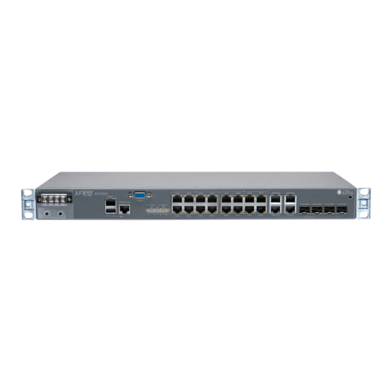
ACX1000 Router Description on page 4 ACX1100 Router Description on page 4 ACX1000 Router Description The ACX1000 routers contain eight T1/E1 ports and twelve Gigabit Ethernet ports, eight of which are RJ-45 ports. The ports labeled COMBO PORTS provide an additional four RJ-45 ports or four Gigabit Ethernet SFP ports. -
Page 23: Acx1000 And Acx1100 Routers Hardware And Cli Terminology Mapping
Figure 3: Front View of the ACX1100 Router Figure 4: Rear View of the ACX1100 Router Related ACX1000 and ACX1100 Routers Hardware and CLI Terminology Mapping on page 5 Documentation LEDs on ACX1000 and ACX1100 Routers on page 35 ACX1000 and ACX1100 Routers Hardware and CLI Terminology Mapping... -
Page 24: Acx1100 Routers Hardware And Cli Terminology Mapping
ACX1000 and ACX1100 Universal Access Router Hardware Guide Table 3: CLI Equivalents of Terms Used in Documentation for ACX1000 Router (continued) Hardware Item (as Value (as displayed Description (as displayed in the in the CLI) displayed in the CLI) CLI) -
Page 25: System Overview
3 4x 1GE (SFP) Xcvr (n) Abbreviated name of the n is a value Optical transceivers “Uplink Ports on ACX1000 and transceiver equivalent to the ACX1100 Routers” on page 32 number of the port in which the transceiver is installed. -
Page 26: Packet Flow On Acx Series Routers
0/1/1 0/1/2 0/1/3 Related ACX1000 and ACX1100 Universal Access Router Overview on page 3 Documentation Packet Flow on ACX Series Routers The class-of-service (CoS) architecture for ACX Series routers is in concept similar to that for MX Series routers. The general architecture for ACX Series routers is shown in... -
Page 27: Protocols And Applications Supported By Acx Series Routers
MTU, apply at interface or family inet levels, and let it calculate for each family automatically. For more information, see the Knowledge Base (KB) article KB28179 at: https://kb.juniper.net/InfoCenter/index?page=content&id=KB28179 Copyright © 2017, Juniper Networks, Inc. -
Page 28: Table 5: Protocols And Applications Supported By Acx Series Routers
ACX1000 and ACX1100 Universal Access Router Hardware Guide Table 5: Protocols and Applications Supported by ACX Series Routers Protocol or Application ACX1000 ACX1100 ACX2000 ACX2100 ACX4000 ACX5048 ACX5096 ACX500 Interface and Encapsulation Types Ethernet interfaces—1G, 12.2 12.2R2 12.2 12.2R2 12.3x51 15.1X54... - Page 29 15.1X54 15.1X54 12.3X54 (OSPF, IS-IS) -D10 –D20 –D20 –D20 (Indoor) 12.3X54 –D25 (Outdoor) Maximum transmission unit 12.2 12.2R2 12.2 12.2R2 12.3x51 15.1X54 15.1X54 12.3X54 (MTU) 1518 -D10 –D20 –D20 –D20 (Indoor) 12.3X54 –D25 (Outdoor) Copyright © 2017, Juniper Networks, Inc.
- Page 30 ACX1000 and ACX1100 Universal Access Router Hardware Guide Table 5: Protocols and Applications Supported by ACX Series Routers (continued) Protocol or Application ACX1000 ACX1100 ACX2000 ACX2100 ACX4000 ACX5048 ACX5096 ACX500 Layer 3 VPNs 12.3R1 12.3R1 12.3R1 12.3R1 12.3x51 15.1X54 15.1X54 12.3X54...
- Page 31 – – – 15.1X54 15.1X54 – –D20 –D20 Ethernet Layer 2 Ethernet in the first mile 12.2 12.2R2 12.2 12.2R2 12.3x51 15.1X54 15.1X54 12.3X54 (EFM 802.3ah) -D10 –D20 –D20 –D20 (Indoor) 12.3X54 –D25 (Outdoor) Copyright © 2017, Juniper Networks, Inc.
- Page 32 ACX1000 and ACX1100 Universal Access Router Hardware Guide Table 5: Protocols and Applications Supported by ACX Series Routers (continued) Protocol or Application ACX1000 ACX1100 ACX2000 ACX2100 ACX4000 ACX5048 ACX5096 ACX500 802.1ag connectivity fault 12.2 12.2R2 12.2 12.2R2 12.3x51 15.1X54 15.1X54 12.3X54...
- Page 33 12.2 12.2R2 12.2 12.2R2 12.3x51 15.1X54 15.1X54 12.3X54 -D10 –D20 –D20 –D20 (Indoor) 12.3X54 –D25 (Outdoor) Priority queuing 12.2 12.2R2 12.2 12.2R2 12.3x51 15.1X54 15.1X54 12.3X54 -D10 –D20 –D20 –D20 (Indoor) 12.3X54 –D25 (Outdoor) Copyright © 2017, Juniper Networks, Inc.
- Page 34 ACX1000 and ACX1100 Universal Access Router Hardware Guide Table 5: Protocols and Applications Supported by ACX Series Routers (continued) Protocol or Application ACX1000 ACX1100 ACX2000 ACX2100 ACX4000 ACX5048 ACX5096 ACX500 Rate control 12.2 12.2R2 12.2 12.2R2 12.3x51 15.1X54 15.1X54 12.3X54 -D10 –D20...
- Page 35 Timing Timing-1588-v2, 12.2 12.2R2 12.2 12.2R2 12.3x51 – – 12.3X54 1588-2008–backup clock -D10 –D20 (Indoor) 12.3X54 –D25 (Outdoor) Synchronous Ethernet 12.2 12.2R2 12.2 12.2R2 12.3x51 – – 12.3X54 -D10 –D20 (Indoor) 12.3X54 –D25 (Outdoor) Copyright © 2017, Juniper Networks, Inc.
- Page 36 ACX1000 and ACX1100 Universal Access Router Hardware Guide Table 5: Protocols and Applications Supported by ACX Series Routers (continued) Protocol or Application ACX1000 ACX1100 ACX2000 ACX2100 ACX4000 ACX5048 ACX5096 ACX500 Building-integrated timing 12.2 12.2R2 12.2 12.2R2 12.3x51 – – 12.3X54...
- Page 37 Layer 2 traceroute 12.2 12.2R2 12.2 12.2R2 12.3x51 15.1X54 15.1X54 12.3X54 -D10 –D20 –D20 –D20 (Indoor) 12.3X54 –D25 (Outdoor) 12.2 12.2R2 12.2 12.2R2 12.3x51 15.1X54 15.1X54 12.3X54 -D10 –D20 –D20 –D20 (Indoor) 12.3X54 –D25 (Outdoor) Copyright © 2017, Juniper Networks, Inc.
- Page 38 ACX1000 and ACX1100 Universal Access Router Hardware Guide Table 5: Protocols and Applications Supported by ACX Series Routers (continued) Protocol or Application ACX1000 ACX1100 ACX2000 ACX2100 ACX4000 ACX5048 ACX5096 ACX500 TFTP for software 12.2 12.2R2 12.2 12.2R2 12.3x51 15.1X54 15.1X54 12.3X54...
- Page 39 12.3x51 15.1X54 15.1X54 12.3X54 -D10 –D20 –D20 –D20 (Indoor) 12.3X54 –D25 (Outdoor) Control plane DOS 12.2 12.2R2 12.2 12.2R2 12.3x51 15.1X54 15.1X54 12.3X54 prevention -D10 –D20 –D20 –D20 (Indoor) 12.3X54 –D25 (Outdoor) High Availability Copyright © 2017, Juniper Networks, Inc.
- Page 40 ACX1000 and ACX1100 Universal Access Router Hardware Guide Table 5: Protocols and Applications Supported by ACX Series Routers (continued) Protocol or Application ACX1000 ACX1100 ACX2000 ACX2100 ACX4000 ACX5048 ACX5096 ACX500 MPLS FRR 12.2 12.2R2 12.2 12.2R2 12.3x51 15.1X54 15.1X54 12.3X54 -D10 –D20...
- Page 41 12.3x51 – – 12.3X54 VP and VC -D10 –D20 (Indoor) 12.3X54 –D25 (Outdoor) Inverse multiplexing over 12.2 12.2R2 12.2 12.2R2 12.3x51 – – 12.3X54 ATM (IMA) -D10 –D20 (Indoor) 12.3X54 –D25 (Outdoor) ATM Encapsulation Copyright © 2017, Juniper Networks, Inc.
- Page 42 ACX1000 and ACX1100 Universal Access Router Hardware Guide Table 5: Protocols and Applications Supported by ACX Series Routers (continued) Protocol or Application ACX1000 ACX1100 ACX2000 ACX2100 ACX4000 ACX5048 ACX5096 ACX500 AAL5 SDU (n-to-1 cell 12.2 12.2R2 12.2 12.2R2 12.3x51 –...
- Page 43 –D20 –D20 –D20 (Indoor) 12.3X54 –D25 (Outdoor) Juniper Networks 12.2 12.2R2 12.2 12.2R2 12.3x51 15.1X54 15.1X54 12.3X54 enterprise-specific MIBs -D10 –D20 –D20 –D20 (Indoor) 12.3X54 –D25 (Outdoor) Related ACX Series Universal Access Routers Documentation Copyright © 2017, Juniper Networks, Inc.
- Page 44 ACX1000 and ACX1100 Universal Access Router Hardware Guide Copyright © 2017, Juniper Networks, Inc.
-
Page 45: Chassis Components And Descriptions
A DE15 alarm cable is required to connect the ACX1000 and ACX1100 router to external alarm devices. Use the gauge wire appropriate for the external device that you are connecting. -
Page 46: Figure 9: Sample Output Alarm-Reporting Device
ACX1000 and ACX1100 Universal Access Router Hardware Guide Table 6: Alarm Relay Contact Functions Contact Name Contact Name Function Contact 1 Normally Open (NO) Current is not flowing through Contact 1 and Contact 2 [REF] when operating normally. When the current flows, the closed alarm is generated. -
Page 47: Clocking Ports On The Acx1000 And Acx1100 Router
Timing input when configured as Ordinary Clock (OC) or Boundary Clock (BC) Timing output when configured as BC Related External Clocking Ports Specifications on the ACX1000 and ACX1100 Router on page 75 Documentation Connecting the ACX1000 or ACX1100 Router to External Clocking Devices on page 98... -
Page 48: Front Panel Of An Acx1000 Router
ACX1000 and ACX1100 Universal Access Router Hardware Guide Front Panel of an ACX1000 Router The front panel of an ACX1000 router consists of the following components (see Figure 11 on page 30): Chassis status LED labeled DC power terminals USB port for upgrading Junos OS... -
Page 49: Front Panel Of An Acx1100 Router
Chapter 2: Chassis Components and Descriptions ACX1000 and ACX1100 Routers Hardware and CLI Terminology Mapping on page 5 LEDs on ACX1000 and ACX1100 Routers on page 35 Front Panel of an ACX1100 Router The front panel of an ACX1100 router consists of the following components (see... -
Page 50: Uplink Ports On Acx1000 And Acx1100 Routers
Related ACX1000 and ACX1100 Universal Access Router Overview on page 3 Documentation ACX1000 and ACX1100 Routers Hardware and CLI Terminology Mapping on page 5 LEDs on ACX1000 and ACX1100 Routers on page 35 Uplink Ports on ACX1000 and ACX1100 Routers Unless otherwise specified, the information about uplink ports applies to both ACX1000 and ACX1100 routers. -
Page 51: T1/E1 Ports
Chapter 2: Chassis Components and Descriptions T1/E1 Ports The ACX1000 router has eight T1/E1 ports located on the front panel. Table 7 on page 33 describes the ports in more detail. Table 7: T1/E1 Port Features Feature Description Line rate E1: 2.048 Mbps per channel... -
Page 52: Gigabit Ethernet Sfp Ports
Feature Description Supported standards See the Hardware Compatibility Tool for the specifications of transceivers supported on the ACX1000 or ACX1100. The list of supported transceivers for the ACX1000 is located at Cable https://pathfinder.juniper.net/hct/product/#prd=ACX1000 The list of supported transceivers for the ACX1100 is located at Connector https://pathfinder.juniper.net/hct/product/#prd=ACX1100... -
Page 53: Leds On Acx1000 And Acx1100 Routers
Router has reported an alarm. On steadily Router has failed. T1/E1 Port LEDs The front panel of the ACX1000 router has eight T1/E1 ports, each with one pair of port LEDs. Table 11 on page 35 describes the LEDs in more detail. -
Page 54: Ethernet Port Leds
ACX1000 and ACX1100 Universal Access Router Hardware Guide Ethernet Port LEDs Each Gigabit Ethernet RJ-45 port on the front panel of the router has one pair of port LEDs. Table 12 on page 36 describes the LEDs in more detail. - Page 55 The port is receiving data. – The port is not receiving data. Related Troubleshooting Resources for ACX1000 and ACX1100 Routers on page 123 Documentation Front Panel of an ACX1000 Router on page 30 Uplink Ports on ACX1000 and ACX1100 Routers on page 32...
- Page 56 ACX1000 and ACX1100 Universal Access Router Hardware Guide Copyright © 2017, Juniper Networks, Inc.
-
Page 57: Cooling System Components And Descriptions
Cooling System Components and Descriptions Cooling System and Airflow in an ACX1000 and ACX1100 Router on page 39 Cooling System and Airflow in an ACX1000 and ACX1100 Router The router does not contain fans and is passively cooled by the heatsinks (see Figure 14 on page 39). - Page 58 ACX1000 and ACX1100 Universal Access Router Hardware Guide Clearance Requirements for Airflow and Hardware Maintenance on ACX1000 and ACX1100 Routers on page 49 ACX1000 and ACX1100 Router Environmental Specifications on page 57 Copyright © 2017, Juniper Networks, Inc.
-
Page 59: Power System Components And Descriptions
Maximum consumed by the router 65 W Related Connecting DC Power Cables to the ACX1000 or ACX1100 Router on page 91 Documentation ACX1000 and ACX1100 DC Power Electrical Safety Guidelines on page 172 ACX1000 and ACX1100 DC Power Specifications on page 63... - Page 60 ACX1000 and ACX1100 Universal Access Router Hardware Guide Copyright © 2017, Juniper Networks, Inc.
-
Page 61: Site Planning, Preparation, And Specifications
Physical Specifications on page 55 Environmental Specifications on page 57 Power Specifications on page 59 Network Cable and Transceiver Planning on page 65 Alarm, Management, and Clocking Cable Specifications and Pinouts on page 71 Copyright © 2017, Juniper Networks, Inc. - Page 62 ACX1000 and ACX1100 Universal Access Router Hardware Guide Copyright © 2017, Juniper Networks, Inc.
-
Page 63: Planning And Preparing The Site
CHAPTER 5 Planning and Preparing the Site Site Preparation Checklist for ACX1000 and ACX1100 Routers on page 45 General Site Guidelines on page 46 Site Electrical Wiring Guidelines on page 47 Site Preparation Checklist for ACX1000 and ACX1100 Routers The checklist in... -
Page 64: General Site Guidelines
Plan the cable routing and management. Related Installing and Connecting an ACX1000 or ACX1100 Router Overview on page 79 Documentation General Site Guidelines on page 46 General Site Guidelines Efficient device operation requires proper site planning and maintenance and proper layout of the equipment, rack or cabinet (if used), and wiring closet. -
Page 65: Site Electrical Wiring Guidelines
Electrical hazards as a result of power surges conducted over the lines into the equipment Related General Safety Guidelines and Warnings on page 139 Documentation General Electrical Safety Guidelines and Warnings on page 167 Prevention of Electrostatic Discharge Damage on page 169 Copyright © 2017, Juniper Networks, Inc. - Page 66 ACX1000 and ACX1100 Universal Access Router Hardware Guide Copyright © 2017, Juniper Networks, Inc.
-
Page 67: Clearance Requirements
CHAPTER 6 Clearance Requirements Clearance Requirements for Airflow and Hardware Maintenance on ACX1000 and ACX1100 Routers on page 49 Clearance Requirements for Airflow and Hardware Maintenance on ACX1000 and ACX1100 Routers When planning the installation site, allow sufficient clearance around the rack (see... -
Page 68: Figure 15: Acx1000 And Acx1100 Chassis Dimensions And Clearance
Rack Requirements for ACX1000 and ACX1100 Routers on page 52 Cabinet Requirements for ACX1000 and ACX1100 Routers on page 51 General Site Guidelines on page 46 Installing and Connecting an ACX1000 or ACX1100 Router Overview on page 79 Copyright © 2017, Juniper Networks, Inc. -
Page 69: Mounting Requirements
Clearance requirements Cabinet airflow requirements Table 18 on page 51 provides the cabinet requirements and specifications for the router. Table 18: Cabinet Requirements and Specifications for the ACX1000 and ACX1100 Router Cabinet Requirement Guidelines Cabinet size You can mount the router in a cabinet that contains a 19-in. -
Page 70: Rack Requirements For Acx1000 And Acx1100 Routers
Clearance Requirements for Airflow and Hardware Maintenance on ACX1000 and ACX1100 Routers on page 49 Installing and Connecting an ACX1000 or ACX1100 Router Overview on page 79 Rack Requirements for ACX1000 and ACX1100 Routers You can mount the router on two-post racks or four-post racks. -
Page 71: Mounting Requirements
Related Cabinet Requirements for ACX1000 and ACX1100 Routers on page 51 Documentation General Site Guidelines on page 46 Installing and Connecting an ACX1000 or ACX1100 Router Overview on page 79 Copyright © 2017, Juniper Networks, Inc. - Page 72 ACX1000 and ACX1100 Universal Access Router Hardware Guide Copyright © 2017, Juniper Networks, Inc.
-
Page 73: Physical Specifications
Physical Specifications Chassis Physical Specifications for ACX1000 and ACX1100 Routers on page 55 Chassis Physical Specifications for ACX1000 and ACX1100 Routers The ACX1000 and ACX1100 router is a rigid sheet-metal structure that houses the hardware components. Table 20 on page 55 summarizes the physical specifications of the ACX1000 and ACX1100 router. - Page 74 ACX1000 and ACX1100 Universal Access Router Hardware Guide Copyright © 2017, Juniper Networks, Inc.
-
Page 75: Environmental Specifications
CHAPTER 9 Environmental Specifications ACX1000 and ACX1100 Router Environmental Specifications on page 57 ACX1000 and ACX1100 Router Environmental Specifications The router must be installed in a rack or cabinet housed in a dry, clean, well-ventilated, and temperature-controlled environment. Ensure that these environmental guidelines are followed: The site must be as dust-free as possible, because dust can clog air intake vents and filters, reducing the efficiency of the router cooling system. - Page 76 Install the router only in restricted areas, such as dedicated equipment rooms and equipment closets, in accordance with Articles 110-16, 110-17, and 110-18 of the National Electrical Code, ANSI/NFPA 70. Related Chassis Physical Specifications for ACX1000 and ACX1100 Routers on page 55 Documentation Copyright © 2017, Juniper Networks, Inc.
-
Page 77: Power Specifications
Two threaded holes are provided on the front of the router chassis for connecting the router to earth ground. The grounding points fit 0.5-inch-long SAE 10-32 screws (American). The grounding points are spaced at 0.625-in. (15.86-mm) centers. Figure 16: Grounding Points on the ACX1000 and ACX1100 Router T1/E1 ACX1000... -
Page 78: Grounding Cable Lug Specifications
ACX1000 and ACX1100 Universal Access Router Hardware Guide NOTE: All bare grounding connection points to the router must be cleaned and coated with an antioxidant solution before grounding the router. NOTE: All surfaces on the router that are unplated must be brought to a bright finish and treated with an antioxidant solution before connecting the router. -
Page 79: Grounding Cable Specifications
You must provide one grounding cable that meets the following specifications: 6-AWG (4.11 mm ), minimum 90°C wire, or as required by the local code. Related Connecting the ACX1000 or ACX1100 Router to Earth Ground on page 89 Documentation Prevention of Electrostatic Discharge Damage on page 169 ACX1100 AC Power Specifications Table 22 on page 61 lists the AC power system electrical specifications. -
Page 80: Table 23: Ac Power Cord Specifications
ACX1000 and ACX1100 Universal Access Router Hardware Guide Table 23 on page 62 provides specifications on the AC power cord provided for each country or region. Table 23: AC Power Cord Specifications Country Model Number Electrical Specification Plug Type Design Standard... -
Page 81: Acx1000 And Acx1100 Dc Power Specifications
Documentation ACX1000 and ACX1100 DC Power Specifications The power supplies in ACX1000 and ACX1100 routers are built in along the front left panel of the chassis with DC power terminals to connect power to the router. The power supplies are labeled When the ACX1100 router are operating normally and both power supplies are switched on, load sharing between them occurs automatically. - Page 82 Related ACX1000 and ACX1100 DC Power Electrical Safety Guidelines on page 172 Documentation DC Power Copper Conductors Warning on page 173 DC Power Disconnection Warning on page 174...
-
Page 83: Network Cable And Transceiver Planning
(JTAC) can help you diagnose the source of the problem. Your JTAC engineer might recommend that you check the third-party optic or cable and potentially replace it with an equivalent Juniper Networks optic or cable that is qualified for the device. -
Page 84: Calculating Power Budget And Power Margin For Fiber-Optic Cables
ACX1000 and ACX1100 Universal Access Router Hardware Guide Calculating Power Budget and Power Margin for Fiber-Optic Cables Use the information in this topic and the specifications for your optical interface to calculate the power budget and power margin for fiber-optic cables. -
Page 85: Network Cable And Transceiver Planning
= 13 dB – 4 dB – 3.5 dB = 5.5 dB In both examples, the calculated power margin is greater than zero, indicating that the link has sufficient power for transmission and does not exceed the maximum receiver input power. Copyright © 2017, Juniper Networks, Inc. -
Page 86: Understanding Fiber-Optic Cable Signal Loss, Attenuation, And Dispersion
ACX1000 and ACX1100 Universal Access Router Hardware Guide Related Understanding Fiber-Optic Cable Signal Loss, Attenuation, and Dispersion on page 68 Documentation Understanding Fiber-Optic Cable Signal Loss, Attenuation, and Dispersion This topic describes signal loss, attenuation, and dispersion in fiber-optic cable. For information about calculating power budget and power margin for fiber-optic cable, see “Calculating Power Budget and Power Margin for Fiber-Optic Cables”... - Page 87 The optical power budget must allow for the sum of component attenuation, power penalties (including those from dispersion), and a safety margin for unexpected losses. Related Determining Transceiver Support and Specifications on page 65 Documentation Copyright © 2017, Juniper Networks, Inc.
- Page 88 ACX1000 and ACX1100 Universal Access Router Hardware Guide Copyright © 2017, Juniper Networks, Inc.
-
Page 89: Alarm, Management, And Clocking Cable Specifications And Pinouts
Management Port Connector Pinout Information for ACX Series Routers on page 73 USB Port Specifications for an ACX Series Router on page 74 External Clocking Ports Specifications on the ACX1000 and ACX1100 Router on page 75 Alarm Contact Port Pinouts for ACX1000 and ACX1100 Routers... - Page 90 ACX1000 and ACX1100 Universal Access Router Overview on page 3 Documentation Front Panel of an ACX1000 Router on page 30 LEDs on ACX1000 and ACX1100 Routers on page 35 Alarm Contact Port on ACX1000 and ACX1100 Routers on page 27 Copyright © 2017, Juniper Networks, Inc.
-
Page 91: Console/Auxiliary Port Connector Pinout On Acx Series Routers
The port uses an autosensing RJ-45 connector to support a 10/100Base-T connection. Two LEDs indicate link/activity on the port and the administrative status of the port. Table 28 on page 74 provides the pinout information for the RJ-45 connector for the management port. Copyright © 2017, Juniper Networks, Inc. -
Page 92: Usb Port Specifications For An Acx Series Router
Console/Auxiliary Port Connector Pinout on ACX Series Routers on page 73 Documentation USB Port Specifications for an ACX Series Router The following Juniper Networks USB flash drives have been tested and are officially supported for the USB port on all ACX Series routers: RE-USB-1G-S... -
Page 93: External Clocking Ports Specifications On The Acx1000 And Acx1100 Router
Front Panel of an ACX2200 Router External Clocking Ports Specifications on the ACX1000 and ACX1100 Router The external clocking port on the ACX1000 and ACX1100 router contains four SMB connectors that support 10 MHz GPS and 1 pulse-per-second (PPS) signals. These signals are internally isolated and have surge protection. - Page 94 ACX1000 and ACX1100 Universal Access Router Hardware Guide Copyright © 2017, Juniper Networks, Inc.
-
Page 95: Initial Installation And Configuration
Connecting the Router to Ground on page 89 Connecting the Router to Power on page 91 Connecting the Router to External Devices on page 95 Installing Components on page 101 Configuring Junos OS on page 103 Copyright © 2017, Juniper Networks, Inc. - Page 96 ACX1000 and ACX1100 Universal Access Router Hardware Guide Copyright © 2017, Juniper Networks, Inc.
-
Page 97: Installation Overview
Connecting ACX1000 or ACX1100 Routers to Management Devices on page 95 Connecting the ACX1000 or ACX1100 Router to an External Alarm-Reporting Device on page 97 Connecting the ACX1000 or ACX1100 Router to External Clocking Devices on page 98 Perform initial configuration of the router. See “Initially Configuring the ACX1000 or ACX1100 Router”... - Page 98 ACX1000 and ACX1100 Universal Access Router Hardware Guide Related Site Preparation Checklist for ACX1000 and ACX1100 Routers on page 45 Documentation General Site Guidelines on page 46 Copyright © 2017, Juniper Networks, Inc.
-
Page 99: Unpacking The Router
Parts Inventory (Packing List) for an ACX1000 and ACX1100 Router on page 82 Unpacking an ACX1000 or ACX1100 Router The ACX1000 and ACX1100 routers are shipped in a cardboard carton, secured with foam packing material. The carton also contains an accessory box. -
Page 100: Parts Inventory (Packing List) For An Acx1000 And Acx1100 Router
Site Preparation Checklist for ACX1000 and ACX1100 Routers on page 45 Parts Inventory (Packing List) for an ACX1000 and ACX1100 Router The ACX1000 and ACX1100 routers are shipped in a cardboard carton, secured with foam packing material. The carton also contains an accessory box. - Page 101 Related ACX1000 and ACX1100 Universal Access Router Overview on page 3 Documentation Unpacking an ACX1000 or ACX1100 Router on page 81 Copyright © 2017, Juniper Networks, Inc.
- Page 102 ACX1000 and ACX1100 Universal Access Router Hardware Guide Copyright © 2017, Juniper Networks, Inc.
-
Page 103: Installing The Router
Installing the Router Installing the ACX1000 or ACX1100 Mounting Brackets on page 85 Installing the ACX1000 or ACX1100 Router in the Rack on page 86 Installing the ACX1000 or ACX1100 Mounting Brackets To attach the mounting brackets, you need the following tools:... -
Page 104: Installing The Acx1000 Or Acx1100 Router In The Rack
ACX1000 and ACX1100 Universal Access Router Hardware Guide Figure 19: Installing the Mounting Brackets to the Rear of the ACX1000 or ACX1100 Router Related Installing and Connecting an ACX1000 or ACX1100 Router Overview on page 79 Documentation Installing the ACX1000 or ACX1100 Router in the Rack on page 86... -
Page 105: Figure 20: Installing The Front-Mounted Router In The Rack
Site Preparation Checklist for ACX1000 and ACX1100 Routers on page 45 Documentation Installing and Connecting an ACX1000 or ACX1100 Router Overview on page 79 Installing the ACX1000 or ACX1100 Mounting Brackets on page 85 Connecting the ACX1000 or ACX1100 Router to Earth Ground on page 89... - Page 106 ACX1000 and ACX1100 Universal Access Router Hardware Guide Copyright © 2017, Juniper Networks, Inc.
-
Page 107: Connecting The Router To Ground
CHAPTER 16 Connecting the Router to Ground Connecting the ACX1000 or ACX1100 Router to Earth Ground on page 89 Connecting the ACX1000 or ACX1100 Router to Earth Ground To ground the DC-powered router, you need the following tools: Phillips (+) screwdriver, number 2... -
Page 108: Figure 21: Grounding Points On The Acx1000 And Acx1100 Router
Installing and Connecting an ACX1000 or ACX1100 Router Overview on page 79 Documentation Connecting DC Power Cables to the ACX1000 or ACX1100 Router on page 91 Prevention of Electrostatic Discharge Damage on page 169 Copyright © 2017, Juniper Networks, Inc. -
Page 109: Connecting The Router To Power
CHAPTER 17 Connecting the Router to Power Connecting DC Power Cables to the ACX1000 or ACX1100 Router on page 91 Connecting AC Power Cords to the ACX1100 Router on page 93 Connecting DC Power Cables to the ACX1000 or ACX1100 Router... - Page 110 ACX1000 and ACX1100 Universal Access Router Hardware Guide For –48V and –60V: a. The cable with very large resistance (indicating an open circuit) to chassis ground is the DC input cable ( – b. The cable with very low resistance (indicating a closed circuit) to chassis ground...
-
Page 111: Connecting Ac Power Cords To The Acx1100 Router
ACX1000 and ACX1100 Power Overview on page 41 Documentation Installing and Connecting an ACX1000 or ACX1100 Router Overview on page 79 Connecting the ACX1000 or ACX1100 Router to Earth Ground on page 89 ACX1000 and ACX1100 DC Power Specifications on page 63... -
Page 112: Figure 23: Connecting Ac Power To The Router
ACX1000 and ACX1100 Universal Access Router Hardware Guide Insert the power cord plug into an external AC power source receptacle. NOTE: Each power supply must be connected to a dedicated AC power feed and a dedicated customer site circuit breaker. We recommend that you use a dedicated customer site circuit breaker rated for 2 A (100 VAC) or 1 A (240 VAC), or as required by local code. -
Page 113: Connecting The Router To External Devices
Connecting the ACX1000 or ACX1100 Router to an External Alarm-Reporting Device on page 97 Connecting the ACX1000 or ACX1100 Router to External Clocking Devices on page 98 Connecting ACX1000 or ACX1100 Routers to Management Devices To connect external devices and cables to the router, you need the following tools:... -
Page 114: Connecting The Router To A Management Console Or Auxiliary Device
ACX1000 and ACX1100 Universal Access Router Hardware Guide Figure 25: Ethernet Port CONSOLE/AUX port Console Server Connecting the Router to a Management Console or Auxiliary Device You can connect a console, laptop, modem, or other auxiliary device by connecting a... - Page 115 Chapter 18: Connecting the Router to External Devices Related Installing and Connecting an ACX1000 or ACX1100 Router Overview on page 79 Documentation General Site Guidelines on page 46 Management Port Connector Pinout Information for ACX Series Routers on page 73...
-
Page 116: Connecting The Acx1000 Or Acx1100 Router To External Clocking Devices
ACX1000 and ACX1100 Universal Access Router Hardware Guide Connecting the ACX1000 or ACX1100 Router to External Clocking Devices The ACX1000 and ACX1100 routers support external clock synchronization for Synchronous Ethernet, T1 or E1 line timing sources, and external inputs. Connecting 1PPS and 10MHz Timing Devices to the Router on page 98... - Page 117 : locked to master CB Selected for : 13 days, 23 hours, 14 minutes, 23 seconds Selected since : 2012-10-29 18:29:29 EDT See Also External Clocking Ports Specifications on the ACX1000 and ACX1100 Router on page 75 Copyright © 2017, Juniper Networks, Inc.
- Page 118 ACX1000 and ACX1100 Universal Access Router Hardware Guide Copyright © 2017, Juniper Networks, Inc.
-
Page 119: Installing Components
CHAPTER 19 Installing Components Installing an ACX1000 or ACX1100 Transceiver on page 101 Installing an ACX1000 or ACX1100 Transceiver To install a transceiver: Attach an ESD grounding strap to your bare wrist and connect the strap to one of the ESD points on the chassis. - Page 120 ACX1000 and ACX1100 Universal Access Router Hardware Guide Related Front Panel of an ACX1000 Router on page 30 Documentation Uplink Ports on ACX1000 and ACX1100 Routers on page 32 Removing an ACX1000 or ACX1100 Transceiver on page 117 Copyright © 2017, Juniper Networks, Inc.
-
Page 121: Configuring Junos Os
Initially Configuring the ACX1000 or ACX1100 Router on page 103 Initially Configuring the ACX1000 or ACX1100 Router The ACX1000 and ACX1100 routers ship with Junos OS preinstalled and ready to be configured when the router is powered on. One 4-GB internal NAND Flash memory device... - Page 122 ACX1000 and ACX1100 Universal Access Router Hardware Guide This procedure connects the router to the network but does not enable it to forward traffic. For complete information about enabling the router to forward traffic, including examples, see the Junos OS configuration guides.
- Page 123 [edit system services] [edit] root@# set system services telnet (Optional) Display the configuration to verify that it is correct. [edit] root@# show system { host-name host-name; domain-name domain-name; backup-router address; root-authentication { authentication-method (password | public-key); Copyright © 2017, Juniper Networks, Inc.
- Page 124 When you have finished configuring the router, exit configuration mode. [edit] root@host# exit root@host> Related ACX1000 and ACX1100 Routers Hardware and CLI Terminology Mapping on page 5 Documentation Protocols and Applications Supported by ACX Series Routers on page 9 Copyright © 2017, Juniper Networks, Inc.
-
Page 125: Maintaining And Replacing Components
PART 4 Maintaining and Replacing Components Routine Maintenance Procedures on page 109 Replacing Chassis Components on page 113 Copyright © 2017, Juniper Networks, Inc. - Page 126 ACX1000 and ACX1100 Universal Access Router Hardware Guide Copyright © 2017, Juniper Networks, Inc.
-
Page 127: Routine Maintenance Procedures
Routine Maintenance Procedures Routine Maintenance Procedures for the ACX1000 and ACX1100 Router on page 109 Maintaining Cables That Connect to ACX1000 and ACX1100 Network Ports on page 109 Maintaining the ACX1000 and ACX1100 Uplink Ports on page 110 Routine Maintenance Procedures for the ACX1000 and ACX1100 Router Purpose For optimum router performance, perform preventive maintenance procedures. -
Page 128: Maintaining The Acx1000 And Acx1100 Uplink Ports
Use only an approved alcohol-free fiber-optic cable cleaning kit, such as the Opptex Cletop-S Fiber Cleaner. Follow the directions for the cleaning kit you use. Related Routine Maintenance Procedures for the ACX1000 and ACX1100 Router on page 109 Documentation Troubleshooting Resources for ACX1000 and ACX1100 Routers on page 123... - Page 129 Chapter 21: Routine Maintenance Procedures PIC 1 Online 8x 1GE(LAN) RJ45 PIC 2 Online 4x 1GE(LAN) SFP, RJ45 Related ACX1000 and ACX1100 Routers Hardware and CLI Terminology Mapping on page 5 Documentation Copyright © 2017, Juniper Networks, Inc.
- Page 130 ACX1000 and ACX1100 Universal Access Router Hardware Guide Copyright © 2017, Juniper Networks, Inc.
-
Page 131: Replacing Chassis Components
Replacing an ACX500 or ACX1100 Console or Auxiliary Cable Removing an ACX500 or ACX1100 Console or Auxiliary Cable on page 113 Installing an ACX1000 or ACX1100 Console or Auxiliary Cable on page 114 Removing an ACX500 or ACX1100 Console or Auxiliary Cable... -
Page 132: Installing An Acx1000 Or Acx1100 Console Or Auxiliary Cable
Console/Auxiliary Port Connector Pinout on ACX Series Routers on page 73 Documentation Replacing an ACX1000 or ACX1100 Management Ethernet Cable Removing an ACX1000 or ACX1100 Management Ethernet Cable on page 114 Installing an ACX1000 and ACX1100 Management Ethernet Cable on page 115 Removing an ACX1000 or ACX1100 Management Ethernet Cable... -
Page 133: Installing An Acx1000 And Acx1100 Management Ethernet Cable
Plug the other end of the cable into the network device. See Also Removing an ACX1000 or ACX1100 Management Ethernet Cable on page 114 Management Port Connector Pinout Information for ACX Series Routers on page 73 Related Management Port Connector Pinout Information for ACX Series Routers on page 73... -
Page 134: Connecting An Acx1000 Or Acx1100 Fiber-Optic Cable
ACX1000 and ACX1100 Universal Access Router Hardware Guide To disconnect a fiber-optic cable from an optical transceiver installed in the router: Disable the port in which the transceiver is installed by issuing the command: [edit interfaces] user@router# set interface-name disable... -
Page 135: Replacing An Acx1000 Or Acx1100 Transceiver
See Also Maintaining Cables That Connect to ACX1000 and ACX1100 Network Ports on page 109 Understanding Fiber-Optic Cable Signal Loss, Attenuation, and Dispersion on page 68 Calculating Power Budget and Power Margin for Fiber-Optic Cables on page 66... -
Page 136: Figure 31: Removing Transceivers
ACX1000 and ACX1100 Universal Access Router Hardware Guide To remove a transceiver (see Figure 31 on page 118): Have ready a replacement transceiver or a transceiver slot plug, an antistatic mat, and a rubber safety cap for the transceiver. Attach an ESD grounding strap to your bare wrist and connect the strap to one of the ESD points on the chassis. -
Page 137: Installing An Acx1000 Or Acx1100 Transceiver
See Also Front Panel of an ACX1000 Router on page 30 Uplink Ports on ACX1000 and ACX1100 Routers on page 32 Installing an ACX1000 or ACX1100 Transceiver on page 101 Installing an ACX1000 or ACX1100 Transceiver... - Page 138 ACX1100 Routers” on page See Also Front Panel of an ACX1000 Router on page 30 Uplink Ports on ACX1000 and ACX1100 Routers on page 32 Removing an ACX1000 or ACX1100 Transceiver on page 117 Copyright © 2017, Juniper Networks, Inc.
-
Page 139: Troubleshooting Hardware
PART 5 Troubleshooting Hardware Troubleshooting Components on page 123 Copyright © 2017, Juniper Networks, Inc. - Page 140 ACX1000 and ACX1100 Universal Access Router Hardware Guide Copyright © 2017, Juniper Networks, Inc.
-
Page 141: Troubleshooting Components
CHAPTER 23 Troubleshooting Components Troubleshooting Resources for ACX1000 and ACX1100 Routers on page 123 Monitoring System Log Messages on page 124 Verifying Active Alarms on page 124 Understanding Alarm Types and Severity Classes on ACX Series Routers on page 125... -
Page 142: Monitoring System Log Messages
ACX1000 and ACX1100 Universal Access Router Hardware Guide For more information on front panel LEDs, see “LEDs on ACX1000 and ACX1100 Routers” on page Related Understanding Alarm Types and Severity Classes on ACX Series Routers on page 125 Documentation Verifying Active Alarms on page 124... -
Page 143: Understanding Alarm Types And Severity Classes On Acx Series Routers
System alarms indicate a missing rescue configuration. System alarms are preset and cannot be modified, although you can configure them to appear automatically in the J-Web interface display or CLI display. Copyright © 2017, Juniper Networks, Inc. -
Page 144: Alarm Severity Classes
ACX1000 and ACX1100 Universal Access Router Hardware Guide Alarm Severity Classes Alarms on ACX Series routers have two severity classes: Major (steady red)—Indicates a critical situation on the router that has resulted from one of the following conditions. A red alarm condition requires immediate action. -
Page 145: Contacting Customer Support And Returning The Chassis Or Components
PART 6 Contacting Customer Support and Returning the Chassis or Components Contacting Customer Support on page 129 Locating Component Serial Numbers on page 131 Packing and Returning Components on page 133 Copyright © 2017, Juniper Networks, Inc. - Page 146 ACX1000 and ACX1100 Universal Access Router Hardware Guide Copyright © 2017, Juniper Networks, Inc.
-
Page 147: Contacting Customer Support
Contacting Customer Support on page 129 Contacting Customer Support You can contact Juniper Networks Technical Assistance Center (JTAC) 24 hours a day, 7 days a week in one of the following ways: On the Web, using the Case Manager link at: http://www.juniper.net/support/... - Page 148 ACX1000 and ACX1100 Universal Access Router Hardware Guide Copyright © 2017, Juniper Networks, Inc.
-
Page 149: Locating Component Serial Numbers
CHAPTER 25 Locating Component Serial Numbers Displaying ACX1000 and ACX1100 Components and Serial Numbers on page 131 ACX1000 and ACX1100 Chassis Serial Number Label on page 132 Displaying ACX1000 and ACX1100 Components and Serial Numbers Before contacting Juniper Networks, Inc. to request a Return Materials Authorization (RMA), you must find the serial number on the router or component. -
Page 150: Acx1000 And Acx1100 Chassis Serial Number Label
Figure 33: ACX1000 Chassis Serial Number Label SN: HS0211483603 Serial number ID label Related Displaying ACX1000 and ACX1100 Components and Serial Numbers on page 131 Documentation Returning a Hardware Component to Juniper Networks, Inc. on page 133 Copyright © 2017, Juniper Networks, Inc. -
Page 151: Packing And Returning Components
Packing the ACX Series Router for Shipment on page 134 Returning a Hardware Component to Juniper Networks, Inc. In the event of a hardware failure, please contact Juniper Networks, Inc. to obtain a Return Material Authorization (RMA) number. If a problem cannot be resolved by the JTAC technician, a Return Materials Authorization (RMA) is issued. -
Page 152: Guidelines For Packing Hardware Components For Shipment
To pack the router for shipment: Retrieve the shipping box and packing materials in which the router was originally shipped. If you do not have these materials, contact your Juniper Networks representative about approved packaging materials. On the console or other management device connected to the Routing Engine, enter CLI operational mode and issue the following command to shut down the router software. - Page 153 Securely tape the box closed. Write the RMA number on the exterior of the box to ensure proper tracking. Related Returning a Hardware Component to Juniper Networks, Inc. on page 133 Documentation Contacting Customer Support on page 129 Copyright © 2017, Juniper Networks, Inc.
- Page 154 ACX1000 and ACX1100 Universal Access Router Hardware Guide Copyright © 2017, Juniper Networks, Inc.
-
Page 155: Safety And Compliance Information
Radiation and Laser Safety Guidelines and Warnings on page 157 Maintenance and Operational Safety Guidelines and Warnings on page 161 Electrical Safety Guidelines and Warnings on page 167 Agency Approvals and Compliance Statements on page 181 Copyright © 2017, Juniper Networks, Inc. - Page 156 ACX1000 and ACX1100 Universal Access Router Hardware Guide Copyright © 2017, Juniper Networks, Inc.
-
Page 157: General Safety Guidelines And Warnings
Operate the device only when it is properly grounded. Ensure that the separate protective earthing terminal provided on this device is permanently connected to earth. Replace fuses only with fuses of the same type and rating. Copyright © 2017, Juniper Networks, Inc. -
Page 158: Definitions Of Safety Warning Levels
ACX1000 and ACX1100 Universal Access Router Hardware Guide Do not open or remove chassis covers or sheet-metal parts unless instructions are provided in the hardware documentation for this device. Such an action could cause severe electrical shock. Do not push or force any objects through any opening in the chassis frame. Such an action could result in electrical shock or fire. - Page 159 Innan du utför arbete på någon utrustning måste du vara medveten om farorna med elkretsar och känna till vanligt förfarande för att förebygga skador. Related General Safety Guidelines and Warnings on page 139 Documentation Copyright © 2017, Juniper Networks, Inc.
-
Page 160: Qualified Personnel Warning
ACX1000 and ACX1100 Universal Access Router Hardware Guide Installation Instructions Warning on page 147 Maintenance and Operational Safety Guidelines and Warnings on page 161 Grounded Equipment Warning on page 154 Laser and LED Safety Guidelines and Warnings on page 158... -
Page 161: Warning Statement For Norway And Sweden
The equipment must be connected to an earthed mains socket-outlet. Advarsel Apparatet skal kobles til en jordet stikkontakt. Varning! Apparaten skall anslutas till jordat nätuttag. Related General Safety Guidelines and Warnings on page 139 Documentation Copyright © 2017, Juniper Networks, Inc. - Page 162 ACX1000 and ACX1100 Universal Access Router Hardware Guide Copyright © 2017, Juniper Networks, Inc.
-
Page 163: Fire Safety Requirements
In addition, you should establish procedures to protect your equipment in the event of a fire emergency. Juniper Networks products should be installed in an environment suitable for electronic equipment. We recommend that fire suppression equipment be available in the event of a fire in the vicinity of the equipment and that all local fire, safety, and electrical codes and ordinances be observed when you install and operate your equipment. - Page 164 To keep warranties effective, do not use a dry chemical fire extinguisher to control a fire at or near a Juniper Networks device. If a dry chemical fire extinguisher is used, the unit is no longer eligible for coverage under a service agreement.
-
Page 165: Installation Safety Guidelines And Warnings
Advarsel Les installasjonsinstruksjonene før systemet kobles til strømkilden. Aviso Leia as instruções de instalação antes de ligar o sistema à sua fonte de energia. ¡Atención! Ver las instrucciones de instalación antes de conectar el sistema a la red de alimentación. Copyright © 2017, Juniper Networks, Inc. -
Page 166: Chassis Lifting Guidelines
ACX1000 and ACX1100 Universal Access Router Hardware Guide Varning! Läs installationsanvisningarna innan du kopplar systemet till dess strömförsörjningsenhet. Related General Safety Guidelines and Warnings on page 139 Documentation Laser and LED Safety Guidelines and Warnings on page 158 Laser and LED Safety Guidelines and Warnings for the ACX5000 Router... - Page 167 Varning! Denna enhet är avsedd för installation i områden med begränsat tillträde. Ett område med begränsat tillträde får endast tillträdas av servicepersonal med ett speciellt verktyg, lås och nyckel, eller annan säkerhetsanordning, och kontrolleras av den auktoritet som ansvarar för området. Copyright © 2017, Juniper Networks, Inc.
-
Page 168: Ramp Warning
ACX1000 and ACX1100 Universal Access Router Hardware Guide Related General Safety Guidelines and Warnings on page 139 Documentation General Electrical Safety Guidelines and Warnings on page 167 Installation Instructions Warning on page 147 Grounded Equipment Warning on page 154 Ramp Warning... - Page 169 De onderstaande richtlijnen worden verstrekt om uw veiligheid te verzekeren: De Juniper Networks switch moet in een stellage worden geïnstalleerd die aan een bouwsel is verankerd. Dit toestel dient onderaan in het rek gemonteerd te worden als het toestel het enige in het rek is.
- Page 170 ACX1000 and ACX1100 Universal Access Router Hardware Guide Le rack sur lequel est monté le Juniper Networks switch doit être fixé à la structure du bâtiment. Si cette unité constitue la seule unité montée en casier, elle doit être placée dans le bas.
- Page 171 Chapter 29: Installation Safety Guidelines and Warnings Juniper Networks switch må installeres i et stativ som er forankret til bygningsstrukturen. Denne enheten bør monteres nederst i kabinettet hvis dette er den eneste enheten i kabinettet. Ved montering av denne enheten i et kabinett som er delvis fylt, skal kabinettet lastes fra bunnen og opp med den tyngste komponenten nederst i kabinettet.
-
Page 172: Grounded Equipment Warning
Följande riktlinjer ges för att trygga din säkerhet: Juniper Networks switch måste installeras i en ställning som är förankrad i byggnadens struktur. Om denna enhet är den enda enheten på ställningen skall den installeras längst ned på... - Page 173 Varning! Denna utrustning är avsedd att jordas. Se till att värdenheten är jordad vid normal användning. Related General Safety Guidelines and Warnings on page 139 Documentation AC Power Electrical Safety Guidelines DC Power Electrical Safety Guidelines for Switches Copyright © 2017, Juniper Networks, Inc.
- Page 174 ACX1000 and ACX1100 Universal Access Router Hardware Guide Copyright © 2017, Juniper Networks, Inc.
-
Page 175: Radiation And Laser Safety Guidelines And Warnings
åpning når det ikke er tilkoblet en fiberkabel. Aviso Dada a possibilidade de emissão de radiação invisível através do orifício da via de acesso, quando esta não tiver nenhum cabo de fibra conectado, Copyright © 2017, Juniper Networks, Inc. -
Page 176: Laser And Led Safety Guidelines And Warnings
Grounded Equipment Warning on page 154 Laser and LED Safety Guidelines and Warnings Juniper Networks devices are equipped with laser transmitters, which are considered a Class 1 Laser Product by the U.S. Food and Drug Administration and are evaluated as a Class 1 Laser Product per EN 60825-1 requirements. -
Page 177: Class 1 Laser Product Warning
Aviso Produto de classe 1 com LED. ¡Atención! Aviso sobre producto LED de Clase 1. Varning! Lysdiodprodukt av klass 1. Laser Beam Warning WARNING: Do not stare into the laser beam or view it directly with optical instruments. Copyright © 2017, Juniper Networks, Inc. - Page 178 ACX1000 and ACX1100 Universal Access Router Hardware Guide Waarschuwing Niet in de straal staren of hem rechtstreeks bekijken met optische instrumenten. Varoitus Älä katso säteeseen äläkä tarkastele sitä suoraan optisen laitteen avulla. Attention Ne pas fixer le faisceau des yeux, ni l'observer directement à l'aide d'instruments optiques.
-
Page 179: Maintenance And Operational Safety Guidelines And Warnings
Attention Danger d'explosion si la pile n'est pas remplacée correctement. Ne la remplacer que par une pile de type semblable ou équivalent, recommandée par le fabricant. Jeter les piles usagées conformément aux instructions du fabricant. Copyright © 2017, Juniper Networks, Inc. -
Page 180: Jewelry Removal Warning
ACX1000 and ACX1100 Universal Access Router Hardware Guide Warnung Bei Einsetzen einer falschen Batterie besteht Explosionsgefahr. Ersetzen Sie die Batterie nur durch den gleichen oder vom Hersteller empfohlenen Batterietyp. Entsorgen Sie die benutzten Batterien nach den Anweisungen des Herstellers. Advarsel Det kan være fare for eksplosjon hvis batteriet skiftes på feil måte. -
Page 181: Lightning Activity Warning
Waarschuwing Tijdens onweer dat gepaard gaat met bliksem, dient u niet aan het systeem te werken of kabels aan te sluiten of te ontkoppelen. Varoitus Älä työskentele järjestelmän parissa äläkä yhdistä tai irrota kaapeleita ukkosilmalla. Copyright © 2017, Juniper Networks, Inc. -
Page 182: Operating Temperature Warning
6 in. (15.2 cm) of clearance around the ventilation openings. Waarschuwing Om te voorkomen dat welke switch van de Juniper Networks router dan ook oververhit raakt, dient u deze niet te bedienen op een plaats waar de maximale aanbevolen omgevingstemperatuur van 40°... -
Page 183: Product Disposal Warning
15,2 cm à volta das aberturas de ventilação. ¡Atención! Para impedir que un encaminador de la serie Juniper Networks switch se recaliente, no lo haga funcionar en un área en la que se supere la temperatura ambiente máxima recomendada de 40°... - Page 184 ACX1000 and ACX1100 Universal Access Router Hardware Guide Advarsel Endelig disponering av dette produktet må skje i henhold til nasjonale lover og forskrifter. Aviso A descartagem final deste produto deverá ser efectuada de acordo com os regulamentos e a legislação nacional.
-
Page 185: Electrical Safety Guidelines And Warnings
ACX1100 AC Power Electrical Safety Guidelines on page 170 AC Power Disconnection Warning on page 171 ACX1000 and ACX1100 DC Power Electrical Safety Guidelines on page 172 DC Power Copper Conductors Warning on page 173 DC Power Disconnection Warning on page 174... -
Page 186: Action To Take After An Electrical Accident
ACX1000 and ACX1100 Universal Access Router Hardware Guide other end of the strap around your bare wrist. Failure to use an ESD grounding strap could result in damage to the device. Install the device in compliance with the following local, national, and international electrical codes: United States—National Fire Protection Association (NFPA 70), United States... -
Page 187: Prevention Of Electrostatic Discharge Damage
(see Figure 34 on page 170). If you are returning a component, place it in an antistatic bag before packing it. Copyright © 2017, Juniper Networks, Inc. -
Page 188: Acx1100 Ac Power Electrical Safety Guidelines
ACX1000 and ACX1100 Universal Access Router Hardware Guide Figure 34: Placing a Component into an Antistatic Bag CAUTION ELECTROSTATIC SENSITIVE DEVICES DO NOT OPEN OR HANDLE EXCEPT AT A STATIC-FREE WORKSTATION CAUTION: ANSI/TIA/EIA-568 cables such as Category 5e and Category 6 can get electrostatically charged. -
Page 189: Ac Power Disconnection Warning
Avvertenza Prima di lavorare su un telaio o intorno ad alimentatori, scollegare il cavo di alimentazione sulle unità CA. Advarsel Før det utføres arbeid på kabinettet eller det arbeides i nærheten av strømforsyningsenheter, skal strømledningen trekkes ut på vekselstrømsenheter. Copyright © 2017, Juniper Networks, Inc. -
Page 190: Acx1000 And Acx1100 Dc Power Electrical Safety Guidelines
ACX1000 and ACX1100 Universal Access Router Hardware Guide Aviso Antes de trabalhar num chassis, ou antes de trabalhar perto de unidades de fornecimento de energia, desligue o cabo de alimentação nas unidades de corrente alternada. ¡Atención! Antes de manipular el chasis de un equipo o trabajar cerca de una fuente de alimentación, desenchufar el cable de alimentación en los equipos... -
Page 191: Dc Power Copper Conductors Warning
Warnung Verwenden Sie ausschließlich Kupferleiter. Avvertenza Usate unicamente dei conduttori di rame. Advarsel Bruk bare kobberledninger. Aviso Utilize apenas fios condutores de cobre. ¡Atención! Emplee sólo conductores de cobre. Varning! Använd endast ledare av koppar. Copyright © 2017, Juniper Networks, Inc. -
Page 192: Dc Power Disconnection Warning
ACX1000 and ACX1100 Universal Access Router Hardware Guide DC Power Disconnection Warning WARNING: Before performing any of the DC power procedures, ensure that power is removed from the DC circuit. To ensure that all power is off, locate the circuit breaker on the panel board that services the DC circuit, switch the circuit breaker to the OFF position, and tape the device handle of the circuit breaker in the OFF position. -
Page 193: Dc Power Grounding Requirements And Warning
Varoitus Laitetta asennettaessa on maahan yhdistäminen aina tehtävä ensiksi ja maadoituksen irti kytkeminen viimeiseksi. Attention Lors de l'installation de l'appareil, la mise à la terre doit toujours être connectée en premier et déconnectée en dernier. Copyright © 2017, Juniper Networks, Inc. -
Page 194: Dc Power Wiring Sequence Warning
ACX1000 and ACX1100 Universal Access Router Hardware Guide Warnung Der Erdanschluß muß bei der Installation der Einheit immer zuerst hergestellt und zuletzt abgetrennt werden. Avvertenza In fase di installazione dell'unità, eseguire sempre per primo il collegamento a massa e disconnetterlo per ultimo. - Page 195 –48 V. Korrekt kopplas kopplingssekvens ar –48 V till –48 V, +RTN till +RTN, jord till jord. Related General Safety Guidelines and Warnings on page 139 Documentation General Electrical Safety Guidelines and Warnings on page 167 Copyright © 2017, Juniper Networks, Inc.
-
Page 196: Dc Power Wiring Terminations Warning
ACX1000 and ACX1100 Universal Access Router Hardware Guide DC Power Electrical Safety Guidelines for Switches DC Power Disconnection Warning on page 174 DC Power Grounding Requirements and Warning on page 175 DC Power Wiring Terminations Warning on page 178 DC Power Wiring Terminations Warning... -
Page 197: Midplane Energy Hazard Warning
Related General Safety Guidelines and Warnings on page 139 Documentation General Electrical Safety Guidelines and Warnings on page 167 AC Power Electrical Safety Guidelines Copyright © 2017, Juniper Networks, Inc. -
Page 198: Tn Power Warning
ACX1000 and ACX1100 Universal Access Router Hardware Guide DC Power Electrical Safety Guidelines for Switches TN Power Warning WARNING: The device is designed to work with a TN power system. Waarschuwing Het apparaat is ontworpen om te functioneren met TN energiesystemen. -
Page 199: Agency Approvals And Compliance Statements
Agency Approvals and Compliance Statements Agency Approvals for ACX1000 and ACX1100 Routers on page 181 Compliance Statements for NEBS for ACX1000 and ACX1100 Routers on page 183 Compliance Statements for EMC Requirements for ACX1000 and ACX1100 Routers on page 183... - Page 200 ACX1000 and ACX1100 Universal Access Router Hardware Guide IEC 60950-1 Information Technology Equipment - Safety - Part 1: General Requirements (with country deviations) EN 60825-1 Safety of Laser Products - Part 1: Equipment Classification, Requirements and User's Guide EN 300 386 V1.3.3 Telecom Network Equipment - EMC Requirements...
-
Page 201: Compliance Statements For Nebs For Acx1000 And Acx1100 Routers
Compliance Statements for EMC Requirements for ACX1000 and ACX1100 Routers Documentation on page 183 Compliance Statements for NEBS for ACX1000 and ACX1100 Routers on page 183 Compliance Statements for Acoustic Noise for ACX1000 and ACX1100 Routers on page 185 Compliance Statements for Environmental Requirements on page 185... -
Page 202: Israel
Related Agency Approvals for ACX1000 and ACX1100 Routers on page 181 Documentation Compliance Statements for NEBS for ACX1000 and ACX1100 Routers on page 183 Compliance Statements for Acoustic Noise for ACX1000 and ACX1100 Routers on page 185 Compliance Statements for Environmental Requirements on page 185... -
Page 203: Compliance Statements For Environmental Requirements
GR-63-CORE: NEBS, Physical Protection GR-1089-CORE: EMC and Electrical Safety for Network Telecommunications Equipment Related Compliance Statements for NEBS for ACX1000 and ACX1100 Routers on page 183 Documentation Compliance Statements for EMC Requirements for ACX1000 and ACX1100 Routers on page 183 Compliance Statements for Environmental Requirements on page 185 Copyright ©... - Page 204 ACX1000 and ACX1100 Universal Access Router Hardware Guide Copyright © 2017, Juniper Networks, Inc.
Need help?
Do you have a question about the ACX1000 and is the answer not in the manual?
Questions and answers